Page 1276 of 4647

BRAKE FLUID
BR-9
C
D
E
G
H
I
J
K
L
MA
B
BR
Revision: 2007 April2007 M35/M45
BRAKE FLUIDPFP:KN100
On-Board Inspection NFS000RV
CHECKING BRAKE FLUID LEVEL
�Make sure that a brake fluid level in reservoir tank is within the
standard (between MAX and MIN lines).
�Visually check around reservoir tank for fluid leakage.
�If the level is excessively low, check brake system for leakage.
�Release parking brake pedal and see if brake warning lamp
goes off. If not, check brake system for fluid leakage.
Checking Brake LineNFS000RW
CAUTION:
If leakage occurs around joints, retighten or, if necessary, replace damaged parts.
1. Check brake line (tubes and hoses) for cracks, deterioration or other damage. Replace any damaged
parts.
2. Check for oil leakage by fully depressing brake pedal while
engine is running.
Drain and RefillNFS000RX
CAUTION:
�Refill with new brake fluid “DOT 3”.
�Never reuse drained brake fluid.
�Be careful not to splash brake fluid on painted areas; it may cause paint damage. If brake fluid is
splashed on painted areas, wash it away with water immediately.
�Before working, disconnect connectors of ABS actuator and electric unit (control unit) or battery
cable from the negative terminal.
1. Connect a vinyl tube to bleed valve.
2. Depress brake pedal, loosen bleed valve, and gradually remove
brake fluid.
SFIA2484E
SBR389C
BRA0007D
Page 1277 of 4647

BR-10
BRAKE FLUID
Revision: 2007 April2007 M35/M45
3. Make sure there is no foreign material in the reservoir tank, and
refill with new brake fluid.
4. Loosen bleed valve, depress brake pedal slowly to full stroke
and then release it. Repeat the procedure every 2 or 3 seconds
until the new brake fluid comes out, then close the bleed valve
while depressing the pedal. Repeat the same work for each
wheel.
5. Bleed air. Refer to BR-10, "
Bleeding Brake System" .
Bleeding Brake System NFS000RY
CAUTION:
�While bleeding, pay attention to master cylinder fluid level.
�Before working, disconnect connectors of ABS actuator and electric unit (control unit) or battery
cable from the negative terminal.
1. Connect a vinyl tube to rear right brake caliper bleed valve.
2. Fully depress brake pedal 4 or 5 times.
3. With brake pedal depressed, loosen bleed valve to bleed air in brake line, and then tighten it immediately.
4. Repeat steps 2 and 3 until all of the air is out of the brake line.
5. Tighten the bleed valve to the specified torque. Refer to front disc brake: BR-22, "
Components" , rear disc
brake: BR-28, "
Components" .
6. From step 1 to 5, with master cylinder reservoir tank filled at least half way, bleed air from brake hydraulic
line bleed valves in the following order:
Rear right brake→Front left brake→Rear left brake→Front right brake
PFIA0403J
Page 1279 of 4647

BR-12
BRAKE TUBE AND HOSE
Revision: 2007 April2007 M35/M45
CAUTION:
�All brake hoses and tubes must be free from excessive bending, twisting and pulling.
�Make sure that there is no interference with other parts when turning steering both clockwise and
counterclockwise.
�Brake tubes and hoses are an important safety part. Always disassemble the parts and retighten
their fittings, if a brake fluid leak is detected. Replace applicable part with a new one, if damaged
part is detected.
�Be careful not to splash brake fluid on painted areas; it may cause paint damage. If brake fluid is
splashed on painted areas, wash it away with water immediately.
�Cover the open end of brake tubes and hoses when disconnecting to prevent entrance of dirt.
�Refill with new brake fluid “DOT 3”.
�Never reuse drained brake fluid.
Removal and Installation of Front Brake Tube and Brake Hose NFS000S0
REMOVAL
1. Drain brake fluid. Refer to BR-9, "Drain and Refill" .
2. Disconnect brake hose from brake tube, using a flare nut wrench.
3. Remove union bolt and remove brake hose from caliper assem-
bly.
4. Remove lock plate and remove brake hose from vehicle.
INSTALLATION
1. Assemble the union bolt and copper washer to the brake hose.
CAUTION:
Do not reuse copper washer.
2. Install brake hose by aligning with the protrusion on brake caliper assembly, and tighten union bolt to the
specified torque. Refer to BR-11, "
Hydraulic Circuit" .
3. Connect brake hose to brake tube, partially tighten flare nut by hand as much as possible, then secure it
to the bracket with lock plate.
4. Using a flare nut torque wrench, tighten flare nut to the specified torque. Refer to BR-11, "
Hydraulic Cir-
cuit" .
5. Refill brake fluid and bleed air. Refer to BR-10, "
Bleeding Brake System" .
Removal and Installation of Rear Brake Tube and Brake Hose NFS000S1
REMOVAL
1. Drain brake fluid. Refer to BR-9, "Drain and Refill" .
A. With out ICC B. With ICC 1. Front disc brake
2. Master cylinder 3. Brake booster 4. Rear disc brake
5. ABS actuator and electric unit (con-
trol unit)6. Connector 7. Brake hose
8. Brake tube
: Flare nut : 18.2 N·m (1.9 kg-m, 13 ft-lb)
: Flare nut : 16.2 N·m (1.7 kg-m, 12 ft-lb)
: Union bolt :18.2 N·m (1.9 kg-m, 13 ft-lb)
: Connector mounting bolt : 7.0 N·m (0.7 kg-m, 62 in-lb)
Refer to GI-11, "
Components" , for the symbols in the figure.
SFIA2964E
Page 1280 of 4647

BRAKE TUBE AND HOSE
BR-13
C
D
E
G
H
I
J
K
L
MA
B
BR
Revision: 2007 April2007 M35/M45
2. Disconnect brake hose from brake tube, using a flare nut wrench.
3. Remove union bolts, and then remove brake hose from brake
caliper assembly.
4. Remove lock plate and then remove brake hose from vehicle.
INSTALLATION
1. Assemble the union bolt and copper washer to the brake hose.
CAUTION:
Do not reuse copper washer.
2. Attach L-shape metal fitting of the brake hose to brake caliper assembly positioning hole, and then tighten
union bolt to the specified torque. Refer to BR-11, "
Hydraulic Circuit" .
3. Connect brake hose to brake tube, partially tighten flare nut by hand as much as possible, then secure it
to the bracket with lock plate.
4. Using a flare nut torque wrench, tighten flare nut to the specified torque. Refer to BR-11, "
Hydraulic Cir-
cuit" .
5. Refill brake fluid and bleed air. Refer to BR-10, "
Bleeding Brake System" .
Inspection after InstallationNFS000S2
CAUTION:
Brake tubes and hoses are important safety parts. Always disassemble the parts and retighten their fit-
tings, if a brake fluid leak is detected. Replace applicable part with a new one, if damaged part is
detected.
1. Check brake lines (tubes and hoses) and connections for fluid leakage, damage, twists, deformation, con-
tacts with other parts, and loose connections. Replace any damage parts.
2. While depressing brake pedal under a force of 785 N (80 kg, 177 lb) with engine running for approximately
5 seconds, then check each part for fluid leakage.
SFIA2049E
Page 1281 of 4647

BR-14
BRAKE MASTER CYLINDER
Revision: 2007 April2007 M35/M45
BRAKE MASTER CYLINDERPFP:46010
On-Board InspectionNFS000S3
LEAK INSPECTION
�Check for leaking in a master cylinder installation surface, a reservoir tank installation surface, and brake
tube connections.
Removal and InstallationNFS000S4
CAUTION:
�Be careful not to splash brake fluid on painted areas; it may cause paint damage. If brake fluid is
splashed on painted areas, wash it away with water immediately.
�Never scratch the piston of master cylinder when installing/removing because the piston is
exposed. Check if any dust is not on the piston, and wash with brake fluid if needed.
�Hold cylinder body when handing master cylinder. Never hold the piston because the piston might
be detached if pulled strongly.
REMOVAL
1. Drain brake fluid. Refer to BR-9, "Drain and Refill" .
2. Disconnect brake fluid level switch harness connector.
3. Disconnect master cylinder brake tubes, using a flare nut wrench.
4. Remove master cylinder mounting nuts and remove master cylinder assembly from vehicle.
INSTALLATION
CAUTION:
�Refill with new brake fluid “DOT 3”.
�Never reuse drained brake fluid.
1. Installation is in the reverse order of removal.
CAUTION:
Apply silicone grease to brake booster (to “A” position in
the figure) when installing master cylinder to brake booster.
2. Tighten brake tube flare nut to the specified torque using a flare
nut torque wrench. Refer to BR-11, "
Hydraulic Circuit" .
3. Refill with new brake fluid and bleed air. Refer to BR-10, "
Bleed-
ing Brake System" .
SFIA2847J
Page 1282 of 4647
BRAKE MASTER CYLINDER
BR-15
C
D
E
G
H
I
J
K
L
MA
B
BR
Revision: 2007 April2007 M35/M45
Disassembly and AssemblyNFS000S5
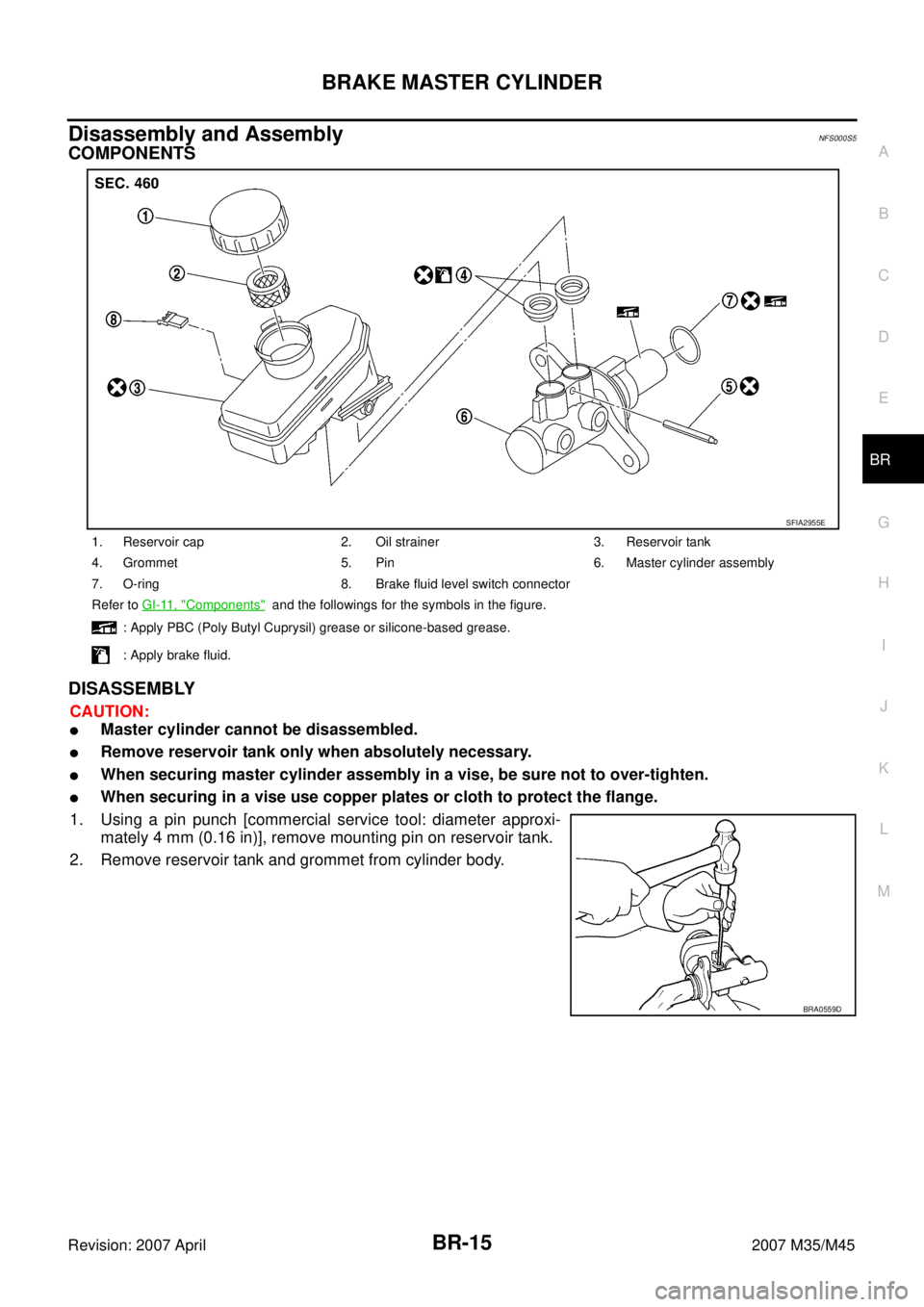
COMPONENTS
DISASSEMBLY
CAUTION:
�Master cylinder cannot be disassembled.
�Remove reservoir tank only when absolutely necessary.
�When securing master cylinder assembly in a vise, be sure not to over-tighten.
�When securing in a vise use copper plates or cloth to protect the flange.
1. Using a pin punch [commercial service tool: diameter approxi-
mately 4 mm (0.16 in)], remove mounting pin on reservoir tank.
2. Remove reservoir tank and grommet from cylinder body.
1. Reservoir cap 2. Oil strainer 3. Reservoir tank
4. Grommet 5. Pin 6. Master cylinder assembly
7. O-ring 8. Brake fluid level switch connector
Refer to GI-11, "
Components" and the followings for the symbols in the figure.
: Apply PBC (Poly Butyl Cuprysil) grease or silicone-based grease.
: Apply brake fluid.
SFIA2955E
BRA0559D
Page 1283 of 4647
BR-16
BRAKE MASTER CYLINDER
Revision: 2007 April2007 M35/M45
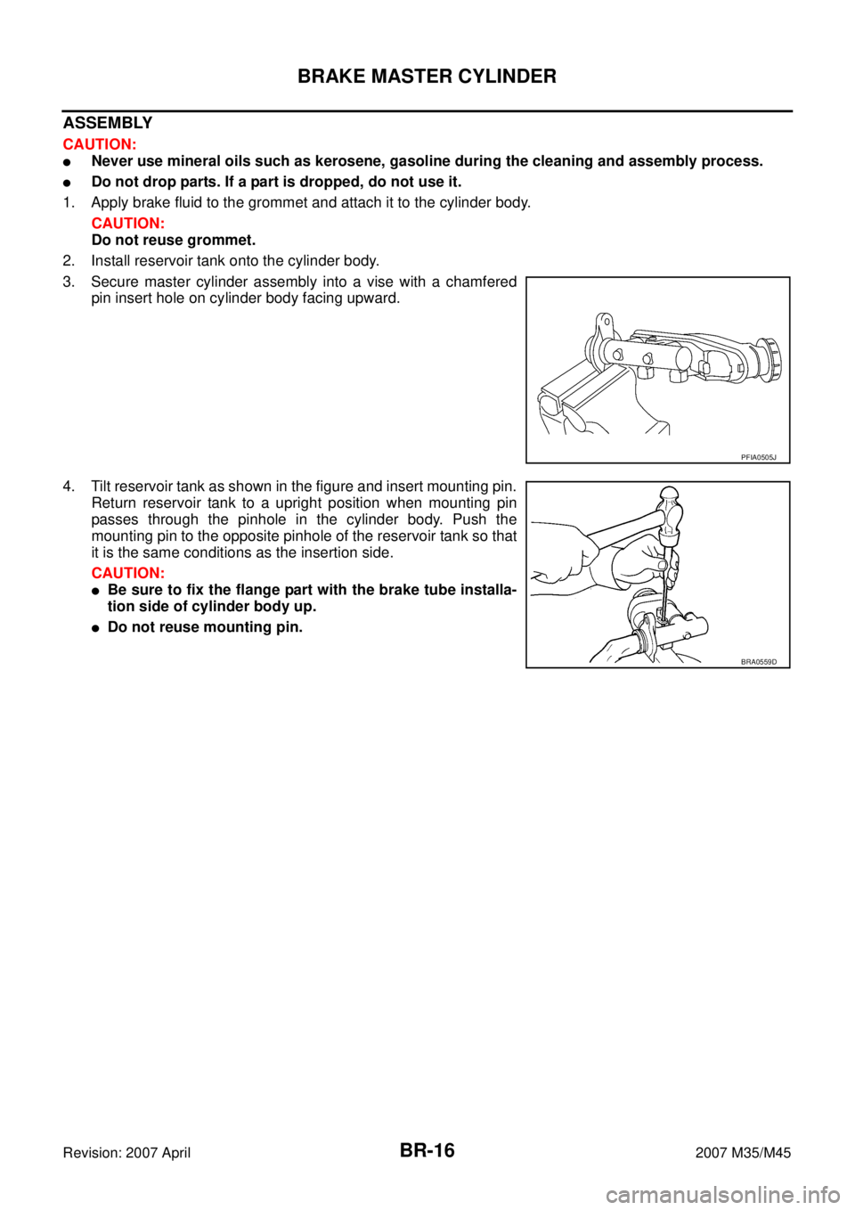
ASSEMBLY
CAUTION:
�Never use mineral oils such as kerosene, gasoline during the cleaning and assembly process.
�Do not drop parts. If a part is dropped, do not use it.
1. Apply brake fluid to the grommet and attach it to the cylinder body.
CAUTION:
Do not reuse grommet.
2. Install reservoir tank onto the cylinder body.
3. Secure master cylinder assembly into a vise with a chamfered
pin insert hole on cylinder body facing upward.
4. Tilt reservoir tank as shown in the figure and insert mounting pin.
Return reservoir tank to a upright position when mounting pin
passes through the pinhole in the cylinder body. Push the
mounting pin to the opposite pinhole of the reservoir tank so that
it is the same conditions as the insertion side.
CAUTION:
�Be sure to fix the flange part with the brake tube installa-
tion side of cylinder body up.
�Do not reuse mounting pin.
PFIA0505J
BRA0559D
Page 1286 of 4647
BRAKE BOOSTER
BR-19
C
D
E
G
H
I
J
K
L
MA
B
BR
Revision: 2007 April2007 M35/M45
4. Install brake pedal bracket mounting nuts and bolt, and tighten them to the specified torque. Refer to BR-
7, "COMPONENTS" .
5. Install vacuum hose into brake booster. Refer to BR-21, "
Removal and Installation" .
6. Install master cylinder to booster assembly. Refer to BR-14, "
Removal and Installation" .
7. Adjust the brake pedal height and the play of the brake pedal. Refer to BR-6, "
ADJUSTMENT" .
8. Tighten lock nut of input rod to the specified torque. Refer to BR-18, "
COMPONENTS" .
9. Connect front left brake tube to ABS actuator and electric unit (control unit). Refer to BR-11, "
Hydraulic
Circuit" .
10. Install cowl top. Refer to EI-18, "
Removal and Installation" .
11. Refill new brake fluid and bleed air. Refer to BR-10, "
Bleeding Brake System" .