Page 3231 of 4647
![INFINITI M35 2007 Factory Service Manual GW-32
POWER WINDOW SYSTEM
Revision: 2007 April2007 M35/M45
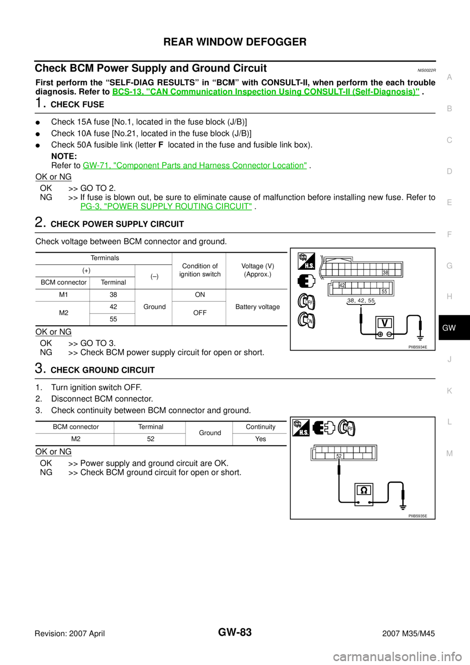
Check BCM Power Supply and Ground CircuitNIS0021R
1. CHECK FUSE
�Check 15A fuse [No. 1, located in fuse block (J/B)]
�Check 10A fuse [No. 21, INFINITI M35 2007 Factory Service Manual GW-32
POWER WINDOW SYSTEM
Revision: 2007 April2007 M35/M45
Check BCM Power Supply and Ground CircuitNIS0021R
1. CHECK FUSE
�Check 15A fuse [No. 1, located in fuse block (J/B)]
�Check 10A fuse [No. 21,](/manual-img/42/57024/w960_57024-3230.png)
GW-32
POWER WINDOW SYSTEM
Revision: 2007 April2007 M35/M45
Check BCM Power Supply and Ground CircuitNIS0021R
1. CHECK FUSE
�Check 15A fuse [No. 1, located in fuse block (J/B)]
�Check 10A fuse [No. 21, located in fuse block (J/B)]
�Check 50A fusible link (letter F , located in the fuse and fusible link box).
NOTE:
Refer to GW-14, "
Component Parts and Harness Connector Location" .
OK or NG
OK >> GO TO 2.
NG >> If fuse is blown out, be sure to eliminate cause of malfunction before installing new fuse. Refer to
PG-3, "
POWER SUPPLY ROUTING CIRCUIT" .
2. CHECK POWER SUPPLY CIRCUIT
Check voltage between BCM connector and ground.
OK or NG
OK >> GO TO 3.
NG >> Check BCM power supply circuit for open or short.
3. CHECK GROUND CIRCUIT
1. Turn ignition switch OFF.
2. Disconnect BCM connector.
3. Check continuity between BCM connector and ground.
OK or NG
OK >> Power supply and ground circuit are OK.
NG >> Check BCM ground circuit for open or short.
Te r m i n a l s
Condition of
ignition switchVoltage (V)
(Approx.) (+)
(–)
BCM connector Terminal
M1 38
GroundON
Battery voltage
M242
OFF
55
PIIB5934E
BCM connector Terminal
GroundContinuity
M2 52 Yes
PIIB5935E
Page 3270 of 4647
REAR WINDOW DEFOGGER
GW-71
C
D
E
F
G
H
J
K
L
MA
B
GW
Revision: 2007 April2007 M35/M45
REAR WINDOW DEFOGGERPFP:25350
Component Parts and Harness Connector LocationNIS0022G
System DescriptionNIS0022H
The rear window defogger system is controlled by BCM and IPDM E/R.
The rear window defogger operates only for approximately 15 minutes.
Power is at all times supplied
�through 20A fuse [No. 75, located in the IPDM E/R]
�to rear window defogger relay terminals 6,
�through 20A fuse [No. 80, located in the IPDM E/R]
�to rear window defogger relay terminals 3,
�through 15A fuse [No. 37, located in the fuse and fusible link box
�to multi-function switch terminal 1,
PIIB6098E
1. Fuse block (J/B) 2. Fuse and fusible link box 3. Fuse block (in IPDM E/R)
4. IPDM E/R E4, E8, E9 5. BCM M1, M2 6.Rear window defogger switch (in
multi function switch) M69
7. Rear window defogger relay E36 8.a : Rear window defogger B604,B701
b : Condenser B49
Page 3282 of 4647

REAR WINDOW DEFOGGER
GW-83
C
D
E
F
G
H
J
K
L
MA
B
GW
Revision: 2007 April2007 M35/M45
Check BCM Power Supply and Ground Circuit NIS0022R
First perform the “SELF-DIAG RESULTS” in “BCM” with CONSULT-II, when perform the each trouble
diagnosis. Refer to BCS-13, "
CAN Communication Inspection Using CONSULT-II (Self-Diagnosis)" .
1. CHECK FUSE
�Check 15A fuse [No.1, located in the fuse block (J/B)]
�Check 10A fuse [No.21, located in the fuse block (J/B)]
�Check 50A fusible link (letter F located in the fuse and fusible link box).
NOTE:
Refer to GW-71, "
Component Parts and Harness Connector Location" .
OK or NG
OK >> GO TO 2.
NG >> If fuse is blown out, be sure to eliminate cause of malfunction before installing new fuse. Refer to
PG-3, "
POWER SUPPLY ROUTING CIRCUIT" .
2. CHECK POWER SUPPLY CIRCUIT
Check voltage between BCM connector and ground.
OK or NG
OK >> GO TO 3.
NG >> Check BCM power supply circuit for open or short.
3. CHECK GROUND CIRCUIT
1. Turn ignition switch OFF.
2. Disconnect BCM connector.
3. Check continuity between BCM connector and ground.
OK or NG
OK >> Power supply and ground circuit are OK.
NG >> Check BCM ground circuit for open or short.
Terminals
Condition of
ignition switchVoltage (V)
(Approx.) (+)
(–)
BCM connector Terminal
M1 38
GroundON
Battery voltage
M242
OFF
55
PIIB5934E
BCM connector Terminal
GroundContinuity
M2 52 Yes
PIIB5935E
Page 3853 of 4647

PG-2Revision: 2007 April2007 M35/M45 BODY NO. 2 HARNESS ...................................... 87
TAIL HARNESS ................................................... 91
ROOM LAMP HARNESS .................................... 92
FRONT DOOR HARNESS .................................. 93
REAR DOOR HARNESS .................................... 94
Wiring Diagram Codes (Cell Codes) ....................... 95
ELECTRICAL UNITS LOCATION ............................. 98
Electrical Units Location ......................................... 98
ENGINE COMPARTMENT .................................. 98
PASSENGER COMPARTMENT ........................100
LUGGAGE COMPARTMENT ............................103
HARNESS CONNECTOR .......................................104
Description ............................................................104
HARNESS CONNECTOR (TAB-LOCKING
TYPE) ................................................................104
HARNESS CONNECTOR (SLIDE-LOCKING TYPE) ................................................................105
HARNESS CONNECTOR (LEVER LOCKING
TYPE) ................................................................106
ELECTRICAL UNITS ..............................................107
Terminal Arrangement ...........................................107
SMJ (SUPER MULTIPLE JUNCTION) ....................109
Terminal Arrangement ...........................................109
STANDARDIZED RELAY ........................................112
Description ............................................................112
NORMAL OPEN, NORMAL CLOSED AND
MIXED TYPE RELAYS ......................................112
TYPE OF STANDARDIZED RELAYS ................112
FUSE BLOCK - JUNCTION BOX (J/B) ..................114
Terminal Arrangement ...........................................114
FUSE, FUSIBLE LINK AND RELAY BOX ..............115
Terminal Arrangement ...........................................115
Page 3883 of 4647

PG-32
PDU (POWER DISTRIBUTION UNIT)
Revision: 2007 April2007 M35/M45
PDU (POWER DISTRIBUTION UNIT)PFP:285F1
Component Parts and Harness Connector LocationNKS004ED
System DescriptionNKS004EE
�PDU (Power Distribution Unit) is the unit that executes the power distribution with the control signal from
the Intelligent Key unit, instead of the mechanical power supply mechanism by conventional key cylinder.
�The push-button ignition switch is operable when the Intelligent Key is within the detention area of the
interior antenna or is inserted to the key slot.
�The push-button ignition switch operation is input to the Intelligent Key unit as a request signal. Then, the
Intelligent Key unit processes the request signal and orders the PDU to switch into the appropriate power
supply position.
NOTE:
The prerequisite for starting the engine varies by the state of brake pedal, A/T selector lever, and vehicle
speed.
�PDU distributes power to each power supply circuit according to the request signal received.
�The power supply position can be confirmed by illumination of the indicators in the upper surroundings of
the push-button ignition switch.
PUSH-BUTTON IGNITION SWITCH OPERATING PROCEDURE
The power supply position switching operation can be performed by the following operation.
NOTE:
�When an Intelligent Key is within the detection area of inside antenna and when it is inserted to the key
slot, it is equivalent to the operations below.
�When starting the engine, the Intelligent Key unit monitors the engine start conditions (brake pedal operat-
ing condition, A/T selector lever position, and vehicle speed).
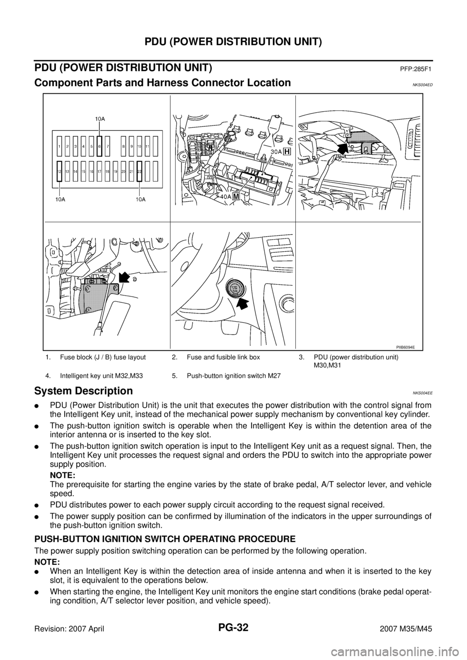
1. Fuse block (J / B) fuse layout 2. Fuse and fusible link box 3. PDU (power distribution unit)
M30,M31
4. Intelligent key unit M32,M33 5. Push-button ignition switch M27
PIIB6094E
Page 4051 of 4647
RF-10
SUNROOF
Revision: 2007 April2007 M35/M45
SUNROOFPFP:91210
Component Parts and Harness Connector LocationNIS0023Q
PIIB6291E
1. Fuse block (J/B) 2. Fuse and fusible link box 3. BCM M1, M2, M3
(View with the glove box assembly removed)
4. Sunroof motor assembly M186 5. Sunroof switch R53 6. Front door switch driver side B11
Page 4058 of 4647

SUNROOF
RF-17
C
D
E
F
G
H
J
K
L
MA
B
RF
Revision: 2007 April2007 M35/M45
Work FlowNIS0023W
1. Check the symptom and customer's requests.
2. Understand the outline of system. Refer to RF-11, "
System Description" .
3. According to the trouble diagnosis chart, repair or replace the cause of the malfunction. Refer to RF-17,
"Diagnosis Symptom Chart" .
4. Does sunroof system operate normally? If Yes, GO TO 5. If No, GO TO 3.
5. INSPECTION END.
Diagnosis Symptom ChartNIS0023X
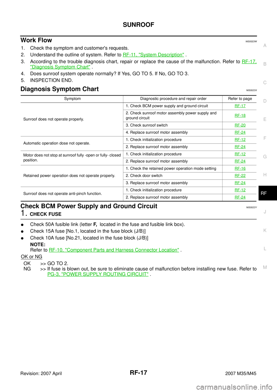
Check BCM Power Supply and Ground Circuit NIS0023Y
1. CHECK FUSE
�Check 50A fusible link (letter F, located in the fuse and fusible link box).
�Check 15A fuse [No.1, located in the fuse block (J/B)]
�Check 10A fuse [No.21, located in the fuse block (J/B)]
NOTE:
Refer to RF-10, "
Component Parts and Harness Connector Location" .
OK or NG
OK >> GO TO 2.
NG >> If fuse is blown out, be sure to eliminate cause of malfunction before installing new fuse. Refer to
PG-3, "
POWER SUPPLY ROUTING CIRCUIT" .
Symptom Diagnostic procedure and repair order Refer to page
Sunroof does not operate properly.1. Check BCM power supply and ground circuit RF-17
2. Check sunroof motor assembly power supply and
ground circuit RF-18
3. Check sunroof switchRF-20
4. Replace sunroof motor assemblyRF-24
Automatic operation dose not operate.1. Check initialization procedureRF-122. Replace sunroof motor assemblyRF-24
Motor does not stop at sunroof fully -open or fully- closed
position.1. Check initialization procedureRF-12
2. Replace sunroof motor assemblyRF-24
Retained power operation does not operate properly.1. Check the retained power operation mode settingRF-162. Check door switchRF-22
3. Replace sunroof motor assemblyRF-24
Sunroof does not operate anti-pinch function.1. Check initialization procedureRF-122. Replace sunroof motor assemblyRF-24
Page 4141 of 4647
![INFINITI M35 2007 Factory Service Manual SB-16
PRE-CRASH SEAT BELT
Revision: 2007 April2007 M35/M45
Check Ignition Power Supply Circuit NHS00089
1. CHECK FUSE
Check 10A fuse [No.15, located in fuse block (J/B)].
NOTE:
Refer to SB-3, "
Compon INFINITI M35 2007 Factory Service Manual SB-16
PRE-CRASH SEAT BELT
Revision: 2007 April2007 M35/M45
Check Ignition Power Supply Circuit NHS00089
1. CHECK FUSE
Check 10A fuse [No.15, located in fuse block (J/B)].
NOTE:
Refer to SB-3, "
Compon](/manual-img/42/57024/w960_57024-4140.png)
SB-16
PRE-CRASH SEAT BELT
Revision: 2007 April2007 M35/M45
Check Ignition Power Supply Circuit NHS00089
1. CHECK FUSE
Check 10A fuse [No.15, located in fuse block (J/B)].
NOTE:
Refer to SB-3, "
Component Parts and Harness Connector Location" .
OK or NG
OK >> GO TO 2.
NG >> If fuse is blown out, be sure to eliminate cause of malfunction before installing new fuse. Refer to
PG-3, "
POWER SUPPLY ROUTING CIRCUIT" .
2. CHECK IGNITION POWER SUPPLY CIRCUIT
1. Turn ignition switch OFF.
2. Disconnect pre-crash seat belt control unit connector.
3. Turn ignition switch ON.
4. Check voltage between pre-crash seat belt control unit harness
connector and ground.
OK or NG
OK >> Ignition power supply circuit is OK.
NG >> Check pre-crash seat belt control unit ignition power supply circuit harness.
Check Motor Power Supply and Ground Circuit [B2454]NHS0008A
1. CHECK FUSE
Check 30A fusible link (letter G , located in the fuse and fusible link box).
NOTE:
Refer to SB-3, "
Component Parts and Harness Connector Location" .
OK or NG
OK >> GO TO 2.
NG >> If fuse is blown out, be sure to eliminate cause of malfunction before installing new fuse. Refer to
PG-3, "
POWER SUPPLY ROUTING CIRCUIT" .
Terminal
Voltage (V)
(Approx.) (+)
(–) Pre-crash seat
belt control unit
connectorTerminal
B142 13 Ground Battery voltage
PHIA1126E