Page 3674 of 4647
NKS003RT
CONSULT-II can display each diagnostic item using the diagnost")
TURN SIGNAL AND HAZARD WARNING LAMPS
LT-223
C
D
E
F
G
H
I
J
L
MA
B
LT
Revision: 2007 April2007 M35/M45
CONSULT-II Functions (BCM)NKS003RT
CONSULT-II can display each diagnostic item using the diagnostic test mode shown following.
CONSULT-II BASIC OPERATION
Refer to GI-38, "CONSULT-II Start Procedure" .
DATA MONITOR
Operation Procedure
1. Touch “FLASHER” on “SELECT TEST ITEM” screen.
2. Touch “DATA MONITOR” on “SELECT DIAG MODE” screen.
3. Touch either “ALL SIGNALS” or “SELECTION FROM MENU” on the “SELECT MONITOR ITEM” screen.
4. When “SELECTION FROM MENU” is selected, touch items to be monitored. When “ALL SIGNALS” is
selected, all the items will be monitored.
5. Touch “START”.
6. Touch “RECORD” while monitoring, then the status of the monitored item can be recorded. To stop
recording, touch “STOP”.
Display Item List
ACTIVE TEST
Operation Procedure
1. Touch “FLASHER” on “SELECT TEST ITEM” screen.
2. Touch “ACTIVE TEST” on “SELECT DIAG MODE” screen.
3. Touch item to be tested and check operation of the selected item.
4. During the operation check, touching “BACK” deactivates the operation.
Display Item List
BCM diagnosis part Diagnosis mode Description
FLASHERDATA MONITOR Displays BCM input data in real time.
ACTIVE TEST Operation of electrical loads can be checked by sending driving signal to them.
ALL SIGNALS Monitors all the signals.
SELECTION FROM MENU Selects items and monitor them.
Monitor item Contents
IGN ON SW “ON/OFF” Displays “IGN position (ON)/OFF, ACC position (OFF)” judged from the ignition switch signal.
HAZARD SW “ON/OFF” Displays “hazard ON (ON)/hazard OFF (OFF)” status, determined from hazard switch signal.
TURN SIGNAL R “ON/OFF” Displays “turn right (ON)/other (OFF)” status, determined from lighting switch signal.
TURN SIGNAL L “ON/OFF” Displays “turn left (ON)/other (OFF)” status, determined from lighting switch signal.
Test item Description
FLASHER (RIGHT) Turn signal lamp (right) can be operated by any ON-OFF operations.
FLASHER (LEFT) Turn signal lamp (left) can be operated by any ON-OFF operations.
Page 3676 of 4647

TURN SIGNAL AND HAZARD WARNING LAMPS
LT-225
C
D
E
F
G
H
I
J
L
MA
B
LT
Revision: 2007 April2007 M35/M45
4. CHECK TURN SIGNAL LAMP CIRCUIT
1. Turn ignition switch OFF.
2. Disconnect BCM connector, front combination lamp RH and LH connector, side turn signal lamp RH and
LH connector, rear combination lamp RH and LH connector.
3. Check continuity between BCM harness connector (A) and front
combination lamp (RH and LH) harness connector (B).
4. Check continuity between BCM harness connector (A) and side
turn signal lamp (RH and LH) harness connector (B).
5. Check continuity between BCM harness connector (A) and rear
combination lamp (RH and LH) harness connector (B).
OK or NG
OK >> GO TO 5.
NG >> Repair harness or connector.
5. CHECK SIGNAL LAMP CIRCUIT (SHORT CIRCUIT)
Check continuity between BCM harness connector and ground.
OK or NG
OK >> Replace BCM. Replace BCM if turn signal lamp does
not work after setting the connector again. Refer to
BCS-15, "
Removal and Installation of BCM" .
NG >> Repair harness or connector.
CircuitAB
Continuity
Connector Terminal Connector Terminal
LH
M245 E55 10
Ye s
RH 46 E49 10
SKIB4807E
CircuitAB
Continuity
Connector Terminal Connector Terminal
LH
M245 E68 1
Ye s
RH 46 E28 1
PKID0504E
CircuitAB
Continuity
Connector Terminal Connector Terminal
LH
M245 B135 3
Ye s
RH 46 B130 3
SKIB4809E
BCM connector Terminal
GroundContinuity
M245
No
46
PKIA6289E
Page 3677 of 4647

LT-226
TURN SIGNAL AND HAZARD WARNING LAMPS
Revision: 2007 April2007 M35/M45
Hazard Warning Lamp Does Not Operate But Turn Signal Lamp OperateNKS003RV
1. CHECK CIRCUIT BETWEEN HAZARD SWITCH AND BCM
With CONSULT-II
1. Select “BCM” on CONSULT-II. Select “FLASHER” on “SELECT
TEST ITEM” screen.
2. Select “DATA MONITOR” on “SELECT DIAG MODE” screen.
Make sure “HAZARD SW” turns ON-OFF linked with operation
of multifunction switch (hazard switch).
Without CONSULT-II
Check voltage between BCM harness connector and ground.
OK or NG
OK >> Replace BCM. Refer to BCS-15, "Removal and Installa-
tion of BCM" .
NG >> GO TO 2.
2. CHECK HAZARD SWITCH BCM CIRCUIT
1. Turn ignition switch OFF.
2. Disconnect BCM connector and multifunction switch connector.
3. Check continuity between BCM harness connector (A) and mul-
tifunction switch harness connector (B).
OK or NG
OK >> GO TO 3.
NG >> Repair harness or connector.When hazard switch is ON position : HAZARD SW ON
PKIA7601E
Terminal
ConditionVoltage
(Approx.) (+)
(-)
Connector Terminal
M1 29 GroundHazard switch is ON. 0 V
Hazard switch is OFF. Battery Voltage
PKIB6809E
AB
Continuity
Connector Terminal Connector Terminal
M1 29 M69 6 Yes
SKIB4812E
Page 3684 of 4647

COMBINATION SWITCH
LT-233
C
D
E
F
G
H
I
J
L
MA
B
LT
Revision: 2007 April2007 M35/M45
Combination Switch Reading FunctionNKS003S6
For details, refer to BCS-3, "COMBINATION SWITCH READING FUNCTION" .
Terminals and Reference Values for BCMNKS003S7
CAUTION:
�Check combination switch system terminal waveform under the loaded condition with lighting
switch, turn signal switch and wiper switch OFF not to be fluctuated by overloaded.
�Turn wiper dial position to 4 except when checking waveform or voltage of wiper dial position.
Wiper dial position can be confirmed on CONSULT-II. Refer to LT- 2 3 8 , "
DATA MONITOR" .
Terminal
No.Wire
colorSignal nameMeasuring condition
Reference value
Ignition
switchOperation or condition
2L/RCombination
switch input 5ONLighting, turn, wiper
switch
(Wiper dial position 4)
Any of several con-
ditions below
�Lighting switch 1ST
�Turn signal switch to
right
�Lighting switch HI
beam (Operates only
HI beam switch)Approx. 1.0 V
Lighting switch 2ND
Approx. 2.0 V
OFF Approx. 0 V
3O/LCombination
switch input 4ONLighting, turn, wiper
switch
(Wiper dial position 4)Front fog lamp switch
ON
Approx. 0.8 V
Any of several con-
ditions below
�Lighting switch 2ND
�Lighting switch
PASSING (Operates
only PASSING switch)
�Turn signal switch to
leftApprox. 1.0 V
OFF Approx. 0 V
PKIB4957J
PKIB4953J
PKIB4955J
PKIB4957J
Page 3685 of 4647

Any of several con-
ditions below
�Lighting switch AUT")
LT-234
COMBINATION SWITCH
Revision: 2007 April2007 M35/M45
4R/GCombination
switch input 3ONLighting, turn, wiper
switch
(Wiper dial position 4)
Any of several con-
ditions below
�Lighting switch AUTO
�Front wiper switch
MIST
�Front wiper switch INT
�Front wiper switch LO
Approx. 1.0 V
OFF Approx. 0 V
5YCombination
switch input 2ONLighting, turn, wiper
switch
Any of several con-
ditions below
�Front washer switch
(Wiper dial position 4)
�Wiper dial position 1
�Wiper dial position 5
�Wiper dial position 6
Approx. 1.0 V
OFF
(Wiper dial position 4)Approx. 0 V
6LG/BCombination
switch input 1ONLighting, turn, wiper
switch
Any of several con-
ditions below
�Front wiper switch HI
(Wiper dial position 4)
�Wiper dial position 3
Approx. 1.0 V
Any of several con-
ditions below
�Wiper dial position 1
�Wiper dial position 2
Approx. 1.7 V
Any of several con-
ditions below
�Wiper dial position 6
�Wiper dial position 7
Approx. 0.8 V
OFF
(Wiper dial position 4)Approx. 0 V Te r m i n a l
No.Wire
colorSignal nameMeasuring condition
Reference value
Ignition
switchOperation or condition
PKIB4957J
PKIB4957J
PKIB4959J
PKIB4952J
PKIB4955J
Page 3686 of 4647
COMBINATION SWITCH
LT-235
C
D
E
F
G
H
I
J
L
MA
B
LT
Revision: 2007 April2007 M35/M45
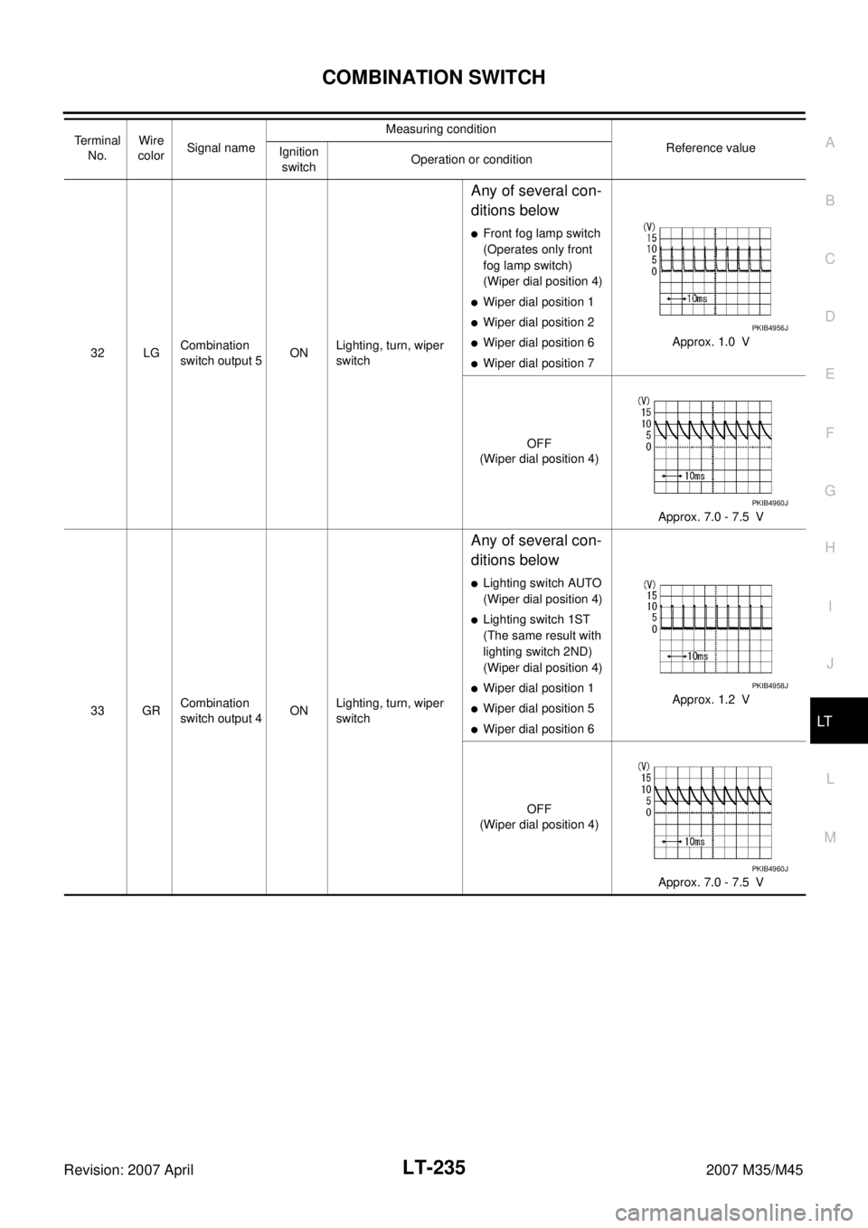
32 LGCombination
switch output 5ONLighting, turn, wiper
switch
Any of several con-
ditions below
�Front fog lamp switch
(Operates only front
fog lamp switch)
(Wiper dial position 4)
�Wiper dial position 1
�Wiper dial position 2
�Wiper dial position 6
�Wiper dial position 7Approx. 1.0 V
OFF
(Wiper dial position 4)
Approx. 7.0 - 7.5 V
33 GRCombination
switch output 4ONLighting, turn, wiper
switch
Any of several con-
ditions below
�Lighting switch AUTO
(Wiper dial position 4)
�Lighting switch 1ST
(The same result with
lighting switch 2ND)
(Wiper dial position 4)
�Wiper dial position 1
�Wiper dial position 5
�Wiper dial position 6Approx. 1.2 V
OFF
(Wiper dial position 4)
Approx. 7.0 - 7.5 V Terminal
No.Wire
colorSignal nameMeasuring condition
Reference value
Ignition
switchOperation or condition
PKIB4956J
PKIB4960J
PKIB4958J
PKIB4960J
Page 3687 of 4647
LT-236
COMBINATION SWITCH
Revision: 2007 April2007 M35/M45
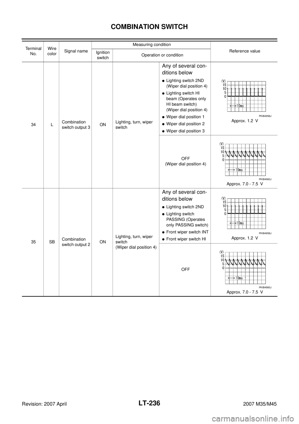
34 LCombination
switch output 3ONLighting, turn, wiper
switch
Any of several con-
ditions below
�Lighting switch 2ND
(Wiper dial position 4)
�Lighting switch HI
beam (Operates only
HI beam switch)
(Wiper dial position 4)
�Wiper dial position 1
�Wiper dial position 2
�Wiper dial position 3Approx. 1.2 V
OFF
(Wiper dial position 4)
Approx. 7.0 - 7.5 V
35 SBCombination
switch output 2ONLighting, turn, wiper
switch
(Wiper dial position 4)
Any of several con-
ditions below
�Lighting switch 2ND
�Lighting switch
PASSING (Operates
only PASSING switch)
�Front wiper switch INT
�Front wiper switch HIApprox. 1.2 V
OFF
Approx. 7.0 - 7.5 V Te r m i n a l
No.Wire
colorSignal nameMeasuring condition
Reference value
Ignition
switchOperation or condition
PKIB4958J
PKIB4960J
PKIB4958J
PKIB4960J
Page 3688 of 4647
COMBINATION SWITCH
LT-237
C
D
E
F
G
H
I
J
L
MA
B
LT
Revision: 2007 April2007 M35/M45
36 VCombination
switch output 1ONLighting, turn, wiper
switch
(Wiper dial position 4)
Any of several con-
ditions below
�Turn signal switch
right
�Turn signal switch left
�Front wiper switch
MIST
�Front wiper switch LO
�Front washer switchApprox. 1.2 V
OFF
(Wiper dial position 4)
Approx. 7.0 - 7.5 V
38 WIgnition switch
(ON) ON — Battery voltage
39 L CAN − H— — —
40 P CAN − L— — —
42 PBattery power
supplyOFF — Battery voltage
52 B Ground ON — Approx. 0 V
55 WBattery power
supplyOFF — Battery voltage Terminal
No.Wire
colorSignal nameMeasuring condition
Reference value
Ignition
switchOperation or condition
PKIB4958J
PKIB4960J

Any of several con-
ditions")