Page 4186 of 4647
CHARGING SYSTEM
SC-25
C
D
E
F
G
H
I
J
L
MA
B
SC
Revision: 2007 April2007 M35/M45
Trouble Diagnosis with Starting/Charging System Tester (Charging)NKS005BZ
For charging system testing, use Starting/Charging System Tester (J-44373). For details and operating
instructions, refer to Technical Service Bulletin.
SKIB0527E
Page 4187 of 4647

SC-26
CHARGING SYSTEM
Revision: 2007 April2007 M35/M45
PRELIMINARY INSPECTION
1. CHECK BATTERY TERMINALS CONNECTION
Check if battery terminals is clean and tight.
OK or NG
OK >> GO TO 2.
NG >> Repair battery terminals connection.
2. CHECK FUSE AND FUSIBLE LINK
Check for blown fuse and fusible link.
OK or NG
OK >> GO TO 3.
NG >> If fuse is blown, be sure to eliminate cause of malfunction before installing new fuse.
3. CHECK “E” TERMINAL CONNECTION
Check if “E” terminal (alternator ground harness) is clean and tight.
OK or NG
OK >> GO TO 4.
NG >> Repair “E” terminal connection.
4. CHECK ALTERNATOR DRIVE BELT TENSION
Check alternator drive belt tension. Refer to the following.
�VQ35DE: EM-17, "Removal and Installation"
�VK45DE: EM-174, "Removal and Installation"
OK or NG
OK >> INSPECTION END
NG >> Repair as needed.
DIAGNOSTIC PROCEDURE 1
Check “L” Terminal Circuit (Open)
1. CHECK “L” TERMINAL CONNECTION
1. Turn ignition switch OFF.
2. Check if “L” terminal is clean and tight.
OK or NG
OK >> GO TO 2.
NG >> Repair “L” terminal connection. Confirm repair by performing complete Starting/Charging system
test. Refer to Technical Service Bulletin.
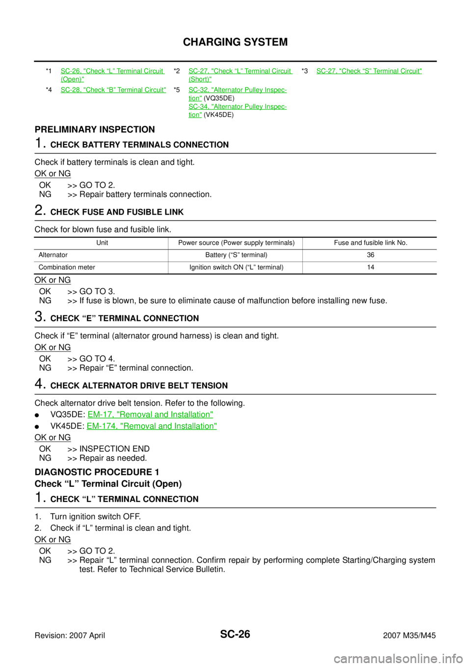
*1SC-26, "Check “L” Terminal Circuit
(Open)"
*2SC-27, "Check “L” Terminal Circuit
(Short)"
*3SC-27, "Check “S” Terminal Circuit"
*4SC-28, "Check “B” Terminal Circuit"*5SC-32, "Alternator Pulley Inspec-
tion" (VQ35DE)
SC-34, "
Alternator Pulley Inspec-
tion" (VK45DE)
Unit Power source (Power supply terminals) Fuse and fusible link No.
Alternator Battery (“S” terminal) 36
Combination meter Ignition switch ON (“L” terminal) 14
Page 4188 of 4647

CHARGING SYSTEM
SC-27
C
D
E
F
G
H
I
J
L
MA
B
SC
Revision: 2007 April2007 M35/M45
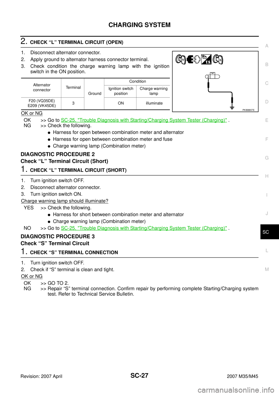
2. CHECK “L” TERMINAL CIRCUIT (OPEN)
1. Disconnect alternator connector.
2. Apply ground to alternator harness connector terminal.
3. Check condition the charge warning lamp with the ignition
switch in the ON position.
OK or NG
OK >> Go to SC-25, "Trouble Diagnosis with Starting/Charging System Tester (Charging)" .
NG >> Check the following.
�Harness for open between combination meter and alternator
�Harness for open between combination meter and fuse
�Charge warning lamp (Combination meter)
DIAGNOSTIC PROCEDURE 2
Check “L” Terminal Circuit (Short)
1. CHECK “L” TERMINAL CIRCUIT (SHORT)
1. Turn ignition switch OFF.
2. Disconnect alternator connector.
3. Turn ignition switch ON.
Charge warning lamp should illuminate?
YES >> Check the following.
�Harness for short between combination meter and alternator
�Charge warning lamp (Combination meter)
NO >> Go to SC-25, "
Trouble Diagnosis with Starting/Charging System Tester (Charging)" .
DIAGNOSTIC PROCEDURE 3
Check “S” Terminal Circuit
1. CHECK “S” TERMINAL CONNECTION
1. Turn ignition switch OFF.
2. Check if “S” terminal is clean and tight.
OK or NG
OK >> GO TO 2.
NG >> Repair “S” terminal connection. Confirm repair by performing complete Starting/Charging system
test. Refer to Technical Service Bulletin.
Alternator
connectorTerminal
GroundCondition
Ignition switch
positionCharge warning
lamp
F20 (VQ35DE)
E209 (VK45DE)3 ON illuminate
PKIB8807E
Page 4189 of 4647

SC-28
CHARGING SYSTEM
Revision: 2007 April2007 M35/M45
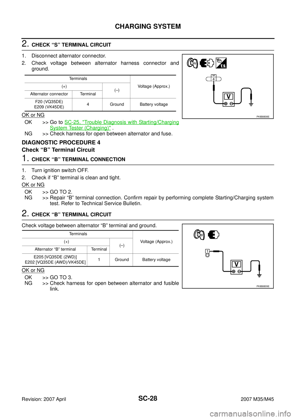
2. CHECK “S” TERMINAL CIRCUIT
1. Disconnect alternator connector.
2. Check voltage between alternator harness connector and
ground.
OK or NG
OK >> Go to SC-25, "Trouble Diagnosis with Starting/Charging
System Tester (Charging)" .
NG >> Check harness for open between alternator and fuse.
DIAGNOSTIC PROCEDURE 4
Check “B” Terminal Circuit
1. CHECK “B” TERMINAL CONNECTION
1. Turn ignition switch OFF.
2. Check if “B” terminal is clean and tight.
OK or NG
OK >> GO TO 2.
NG >> Repair “B” terminal connection. Confirm repair by performing complete Starting/Charging system
test. Refer to Technical Service Bulletin.
2. CHECK “B” TERMINAL CIRCUIT
Check voltage between alternator “B” terminal and ground.
OK or NG
OK >> GO TO 3.
NG >> Check harness for open between alternator and fusible
link.
Terminals
Voltage (Approx.) (+)
(–)
Alternator connector Terminal
F20 (VQ35DE)
E209 (VK45DE)4 Ground Battery voltage
PKIB8808E
Terminals
Voltage (Approx.) (+)
(–)
Alternator “B” terminal Terminal
E205 [VQ35DE (2WD)]
E202 [VQ35DE (AWD)/VK45DE]1 Ground Battery voltage
PKIB8809E
Page 4190 of 4647

CHARGING SYSTEM
SC-29
C
D
E
F
G
H
I
J
L
MA
B
SC
Revision: 2007 April2007 M35/M45
3. CHECK “B” TERMINAL CONNECTION (VOLTAGE DROP TEST)
1. Start engine, then engine running at idle and warm.
2. Check voltage between battery positive terminal and alternator
“B” terminal.
OK or NG
OK >> Go to SC-25, "Trouble Diagnosis with Starting/Charging
System Tester (Charging)" .
NG >> Check harness between battery and alternator for poor continuity.
Power Generation Voltage Variable Control System Operation InspectionNKS003NQ
CAUTION:
�For this model, the battery current sensor that is installed to the battery cable at the negative ter-
minal measures the charging/discharging current of the battery, and performs various controls. If
the electrical component or the ground wire is connected directly to the battery terminal, the cur-
rent other than that being measured with the battery current sensor is charging to or discharging
from the battery. This condition causes the malfunction of the control, and then the battery dis-
charge may occur. Never connect the electrical component or the ground wire directly to the bat-
tery terminal.
�When performing this inspection, always use the charged battery that completed the battery
inspection. (When the charging rate of the battery is low, the response speed of the voltage
change will become slow. This is a cause of an incorrect inspection.)
INSPECTION PROCEDURE
1. CHECK ECM (CONSULT-II)
Perform ECM self-diagnosis with CONSULT-II. Refer to the following.
�VQ35DE: EC-123, "CONSULT-II Function (ENGINE)"
�VK45DE: EC-826, "CONSULT-II Function (ENGINE)"
Self-diagnostic results content
No malfunction detected>> GO TO 2.
Malfunction detected>> Check applicable parts, and repair or replace corresponding parts.
Terminals
Voltage
(Approx.)
(+)(–)
Alternator “B” terminal Terminal
Battery positive
terminalE205 [VQ35DE (2WD)]
E202 [VQ35DE (AWD)/VK45DE]1 Less than 0.2 V
PKIB8810E
Page 4481 of 4647
![INFINITI M35 2007 Factory Service Manual STC-42
[RAS]
TROUBLE DIAGNOSIS
Revision: 2007 April2007 M35/M45
4. CHECK REAR WHEEL STEERING ANGLE SENSOR OUTPUT SIGNAL
1. Connect rear wheel steering angle sensor harness connector B465.
2. Check vol INFINITI M35 2007 Factory Service Manual STC-42
[RAS]
TROUBLE DIAGNOSIS
Revision: 2007 April2007 M35/M45
4. CHECK REAR WHEEL STEERING ANGLE SENSOR OUTPUT SIGNAL
1. Connect rear wheel steering angle sensor harness connector B465.
2. Check vol](/manual-img/42/57024/w960_57024-4480.png)
STC-42
[RAS]
TROUBLE DIAGNOSIS
Revision: 2007 April2007 M35/M45
4. CHECK REAR WHEEL STEERING ANGLE SENSOR OUTPUT SIGNAL
1. Connect rear wheel steering angle sensor harness connector B465.
2. Check voltage RAS control unit harness connector B476 when
starting the engine and turning the steering wheel from neutral
position clockwise/counterclockwise by 180°.
CAUTION:
There is approximately 1 V or more difference between main output and sub output at straight-ahead position, inspection
results are “NG”.
OK or NG
OK >> RAS control unit malfunction. Replace RAS control unit.
NG >> GO TO 5.
5. CHECK REAR WHEEL STEERING ANGLE SENSOR OUTPUT SIGNAL CIRCUIT
1. Turn ignition switch OFF, disconnect rear wheel steering angle sensor harness connector B465 and RAS
control unit harness connector B476.
2. Check continuity between each harness connector of rear wheel
steering angle sensor harness connector B465 (A) and RAS
control unit harness connector B476 (B).
OK or NG
OK >> Rear wheel steering angle sensor malfunction. Replace
rear wheel steering angle sensor.
NG >> Harness between rear wheel steering angle sensor and
RAS control unit open or shorted. Repair or replace harness.
SGIA1275E
Steering conditionRear wheel steering angle sensor
Rear main output
Terminal 4 (+) - 15 (-)Rear sub output
Terminal 7 (+) - 15 (-)
Straight-ahead (neutral position) Approx. 2.4 V Approx. 2.4 V
Turn wheel to the right by 180°Approx. 4.4 V Approx. 4.4 V
Turn wheel to the left by 180°Approx. 0.4 V Approx. 0.4 V
Rear wheel steering angle sensor RAS control unit Continuity
Terminal 2 Terminal 7 Yes
Terminal 4 Terminal 4 Yes
SGIA1651E