Page 4090 of 4647
REAR FINAL DRIVE ASSEMBLY
RFD-21
C
E
F
G
H
I
J
K
L
MA
B
RFD
Revision: 2007 April2007 M35/M45
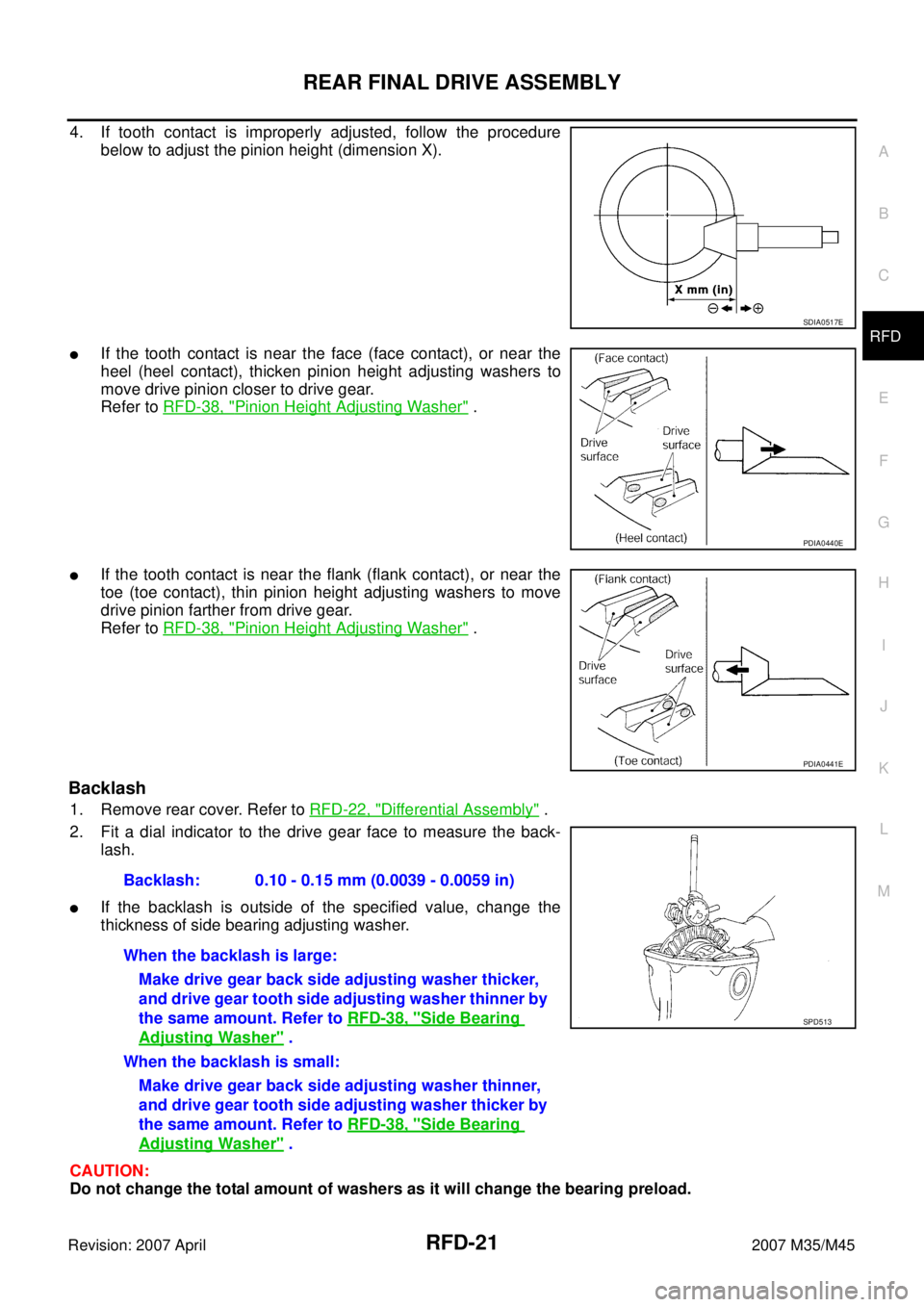
4. If tooth contact is improperly adjusted, follow the procedure
below to adjust the pinion height (dimension X).
�If the tooth contact is near the face (face contact), or near the
heel (heel contact), thicken pinion height adjusting washers to
move drive pinion closer to drive gear.
Refer to RFD-38, "
Pinion Height Adjusting Washer" .
�If the tooth contact is near the flank (flank contact), or near the
toe (toe contact), thin pinion height adjusting washers to move
drive pinion farther from drive gear.
Refer to RFD-38, "
Pinion Height Adjusting Washer" .
Backlash
1. Remove rear cover. Refer to RFD-22, "Differential Assembly" .
2. Fit a dial indicator to the drive gear face to measure the back-
lash.
�If the backlash is outside of the specified value, change the
thickness of side bearing adjusting washer.
CAUTION:
Do not change the total amount of washers as it will change the bearing preload.
SDIA0517E
PDIA0440E
PDIA0441E
Backlash: 0.10 - 0.15 mm (0.0039 - 0.0059 in)
When the backlash is large:
Make drive gear back side adjusting washer thicker,
and drive gear tooth side adjusting washer thinner by
the same amount. Refer to RFD-38, "
Side Bearing
Adjusting Washer" .
When the backlash is small:
Make drive gear back side adjusting washer thinner,
and drive gear tooth side adjusting washer thicker by
the same amount. Refer to RFD-38, "
Side Bearing
Adjusting Washer" .
SPD513
Page 4094 of 4647
REAR FINAL DRIVE ASSEMBLY
RFD-25
C
E
F
G
H
I
J
K
L
MA
B
RFD
Revision: 2007 April2007 M35/M45
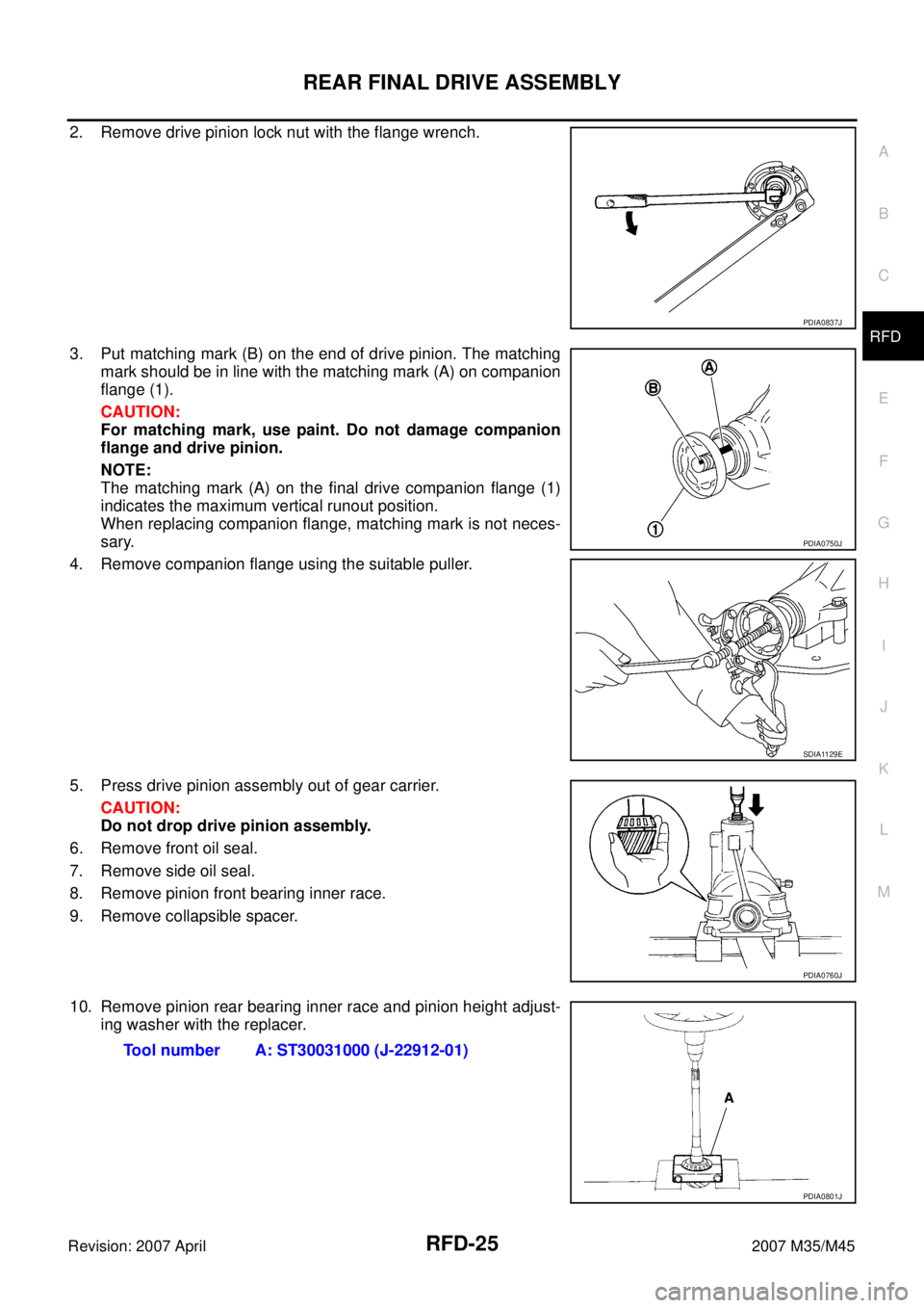
2. Remove drive pinion lock nut with the flange wrench.
3. Put matching mark (B) on the end of drive pinion. The matching
mark should be in line with the matching mark (A) on companion
flange (1).
CAUTION:
For matching mark, use paint. Do not damage companion
flange and drive pinion.
NOTE:
The matching mark (A) on the final drive companion flange (1)
indicates the maximum vertical runout position.
When replacing companion flange, matching mark is not neces-
sary.
4. Remove companion flange using the suitable puller.
5. Press drive pinion assembly out of gear carrier.
CAUTION:
Do not drop drive pinion assembly.
6. Remove front oil seal.
7. Remove side oil seal.
8. Remove pinion front bearing inner race.
9. Remove collapsible spacer.
10. Remove pinion rear bearing inner race and pinion height adjust-
ing washer with the replacer.
PDIA0837J
PDIA0750J
SDIA1129E
PDIA0760J
Tool number A: ST30031000 (J-22912-01)
PDIA0801J
Page 4097 of 4647
RFD-28
REAR FINAL DRIVE ASSEMBLY
Revision: 2007 April2007 M35/M45
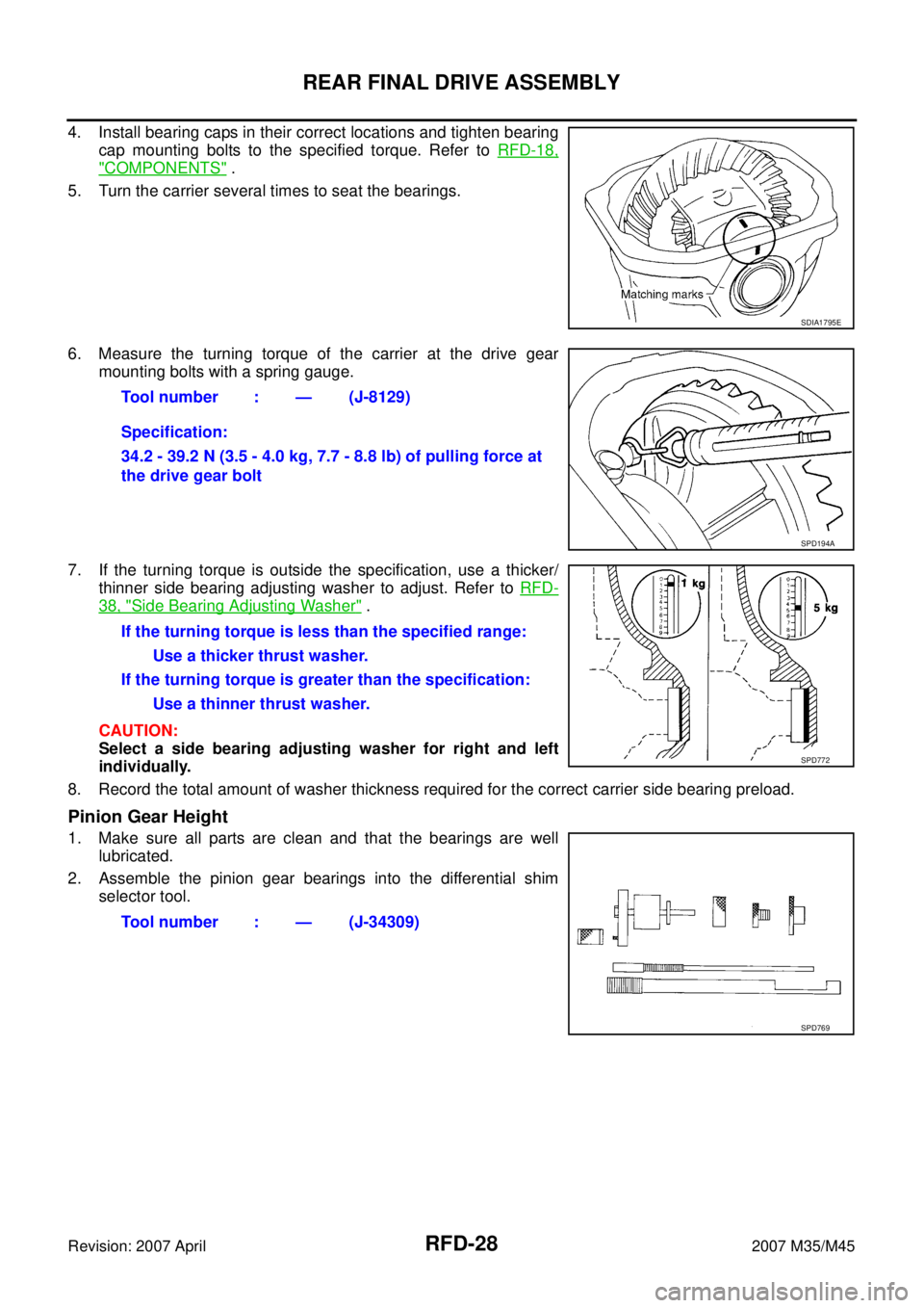
4. Install bearing caps in their correct locations and tighten bearing
cap mounting bolts to the specified torque. Refer to RFD-18,
"COMPONENTS" .
5. Turn the carrier several times to seat the bearings.
6. Measure the turning torque of the carrier at the drive gear
mounting bolts with a spring gauge.
7. If the turning torque is outside the specification, use a thicker/
thinner side bearing adjusting washer to adjust. Refer to RFD-
38, "Side Bearing Adjusting Washer" .
CAUTION:
Select a side bearing adjusting washer for right and left
individually.
8. Record the total amount of washer thickness required for the correct carrier side bearing preload.
Pinion Gear Height
1. Make sure all parts are clean and that the bearings are well
lubricated.
2. Assemble the pinion gear bearings into the differential shim
selector tool.
SDIA1795E
Tool number : — (J-8129)
Specification:
34.2 - 39.2 N (3.5 - 4.0 kg, 7.7 - 8.8 lb) of pulling force at
the drive gear bolt
SPD194A
If the turning torque is less than the specified range:
Use a thicker thrust washer.
If the turning torque is greater than the specification:
Use a thinner thrust washer.
SPD772
Tool number : — (J-34309)
SPD769
Page 4098 of 4647
REAR FINAL DRIVE ASSEMBLY
RFD-29
C
E
F
G
H
I
J
K
L
MA
B
RFD
Revision: 2007 April2007 M35/M45
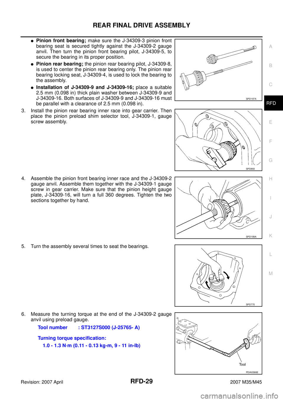
�Pinion front bearing; make sure the J-34309-3 pinion front
bearing seat is secured tightly against the J-34309-2 gauge
anvil. Then turn the pinion front bearing pilot, J-34309-5, to
secure the bearing in its proper position.
�Pinion rear bearing; the pinion rear bearing pilot, J-34309-8,
is used to center the pinion rear bearing only. The pinion rear
bearing locking seat, J-34309-4, is used to lock the bearing to
the assembly.
�Installation of J-34309-9 and J-34309-16; place a suitable
2.5 mm (0.098 in) thick plain washer between J-34309-9 and
J-34309-16. Both surfaces of J-34309-9 and J-34309-16 must
be parallel with a clearance of 2.5 mm (0.098 in).
3. Install the pinion rear bearing inner race into gear carrier. Then
place the pinion preload shim selector tool, J-34309-1, gauge
screw assembly.
4. Assemble the pinion front bearing inner race and the J-34309-2
gauge anvil. Assemble them together with the J-34309-1 gauge
screw in gear carrier. Make sure that the pinion height gauge
plate, J-34309-16, will turn a full 360 degrees. Tighten the two
sections together by hand.
5. Turn the assembly several times to seat the bearings.
6. Measure the turning torque at the end of the J-34309-2 gauge
anvil using preload gauge.
SPD197A
SPD893
SPD199A
SPD770
Tool number : ST3127S000 (J-25765- A)
Turning torque specification:
1.0 - 1.3 N·m (0.11 - 0.13 kg-m, 9 - 11 in-lb)
PDIA0566E
Page 4099 of 4647
RFD-30
REAR FINAL DRIVE ASSEMBLY
Revision: 2007 April2007 M35/M45
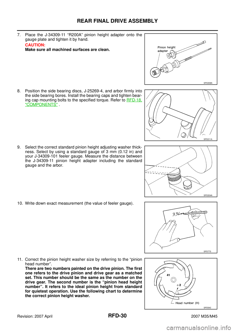
7. Place the J-34309-11 “R200A” pinion height adapter onto the
gauge plate and tighten it by hand.
CAUTION:
Make sure all machined surfaces are clean.
8. Position the side bearing discs, J-25269-4, and arbor firmly into
the side bearing bores. Install the bearing caps and tighten bear-
ing cap mounting bolts to the specified torque. Refer to RFD-18,
"COMPONENTS" .
9. Select the correct standard pinion height adjusting washer thick-
ness. Select by using a standard gauge of 3 mm (0.12 in) and
your J-34309-101 feeler gauge. Measure the distance between
the J-34309-11 pinion height adapter including the standard
gauge and the arbor.
10. Write down exact measurement (the value of feeler gauge).
11. Correct the pinion height washer size by referring to the “pinion
head number”.
There are two numbers painted on the drive pinion. The first
one refers to the drive pinion and drive gear as a matched
set. This number should be the same as the number on the
drive gear. The second number is the “pinion head height
number”. It refers to the ideal pinion height from standard
for quietest operation. Use the following chart to determine
the correct pinion height washer.
SPD208A
SPD211A
SPD204A
SPD775
SPD542
Page 4100 of 4647
REAR FINAL DRIVE ASSEMBLY
RFD-31
C
E
F
G
H
I
J
K
L
MA
B
RFD
Revision: 2007 April2007 M35/M45
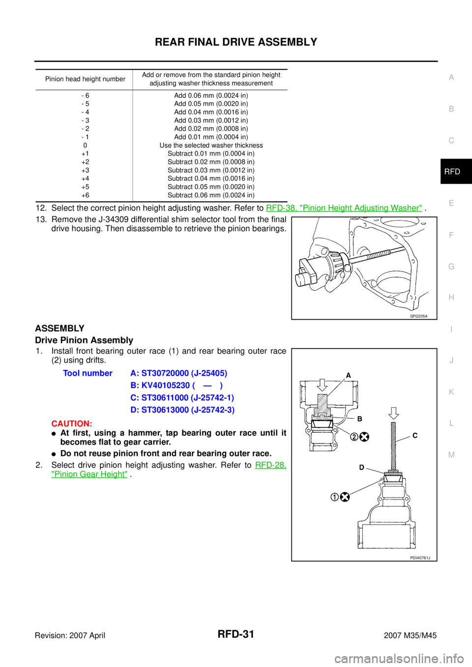
12. Select the correct pinion height adjusting washer. Refer to RFD-38, "Pinion Height Adjusting Washer" .
13. Remove the J-34309 differential shim selector tool from the final
drive housing. Then disassemble to retrieve the pinion bearings.
ASSEMBLY
Drive Pinion Assembly
1. Install front bearing outer race (1) and rear bearing outer race
(2) using drifts.
CAUTION:
�At first, using a hammer, tap bearing outer race until it
becomes flat to gear carrier.
�Do not reuse pinion front and rear bearing outer race.
2. Select drive pinion height adjusting washer. Refer to RFD-28,
"Pinion Gear Height" .
Pinion head height numberAdd or remove from the standard pinion height
adjusting washer thickness measurement
- 6
- 5
- 4
- 3
- 2
- 1
0
+1
+2
+3
+4
+5
+6Add 0.06 mm (0.0024 in)
Add 0.05 mm (0.0020 in)
Add 0.04 mm (0.0016 in)
Add 0.03 mm (0.0012 in)
Add 0.02 mm (0.0008 in)
Add 0.01 mm (0.0004 in)
Use the selected washer thickness
Subtract 0.01 mm (0.0004 in)
Subtract 0.02 mm (0.0008 in)
Subtract 0.03 mm (0.0012 in)
Subtract 0.04 mm (0.0016 in)
Subtract 0.05 mm (0.0020 in)
Subtract 0.06 mm (0.0024 in)
SPD205A
Tool number A: ST30720000 (J-25405)
B: KV40105230 ( — )
C: ST30611000 (J-25742-1)
D: ST30613000 (J-25742-3)
PDIA0761J
Page 4101 of 4647
RFD-32
REAR FINAL DRIVE ASSEMBLY
Revision: 2007 April2007 M35/M45
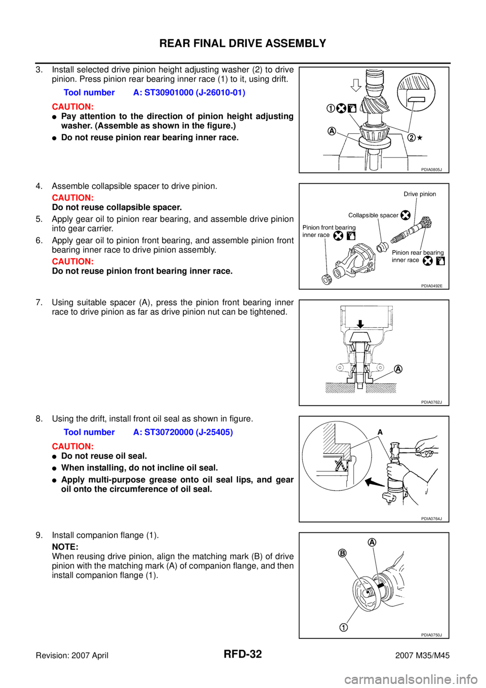
3. Install selected drive pinion height adjusting washer (2) to drive
pinion. Press pinion rear bearing inner race (1) to it, using drift.
CAUTION:
�Pay attention to the direction of pinion height adjusting
washer. (Assemble as shown in the figure.)
�Do not reuse pinion rear bearing inner race.
4. Assemble collapsible spacer to drive pinion.
CAUTION:
Do not reuse collapsible spacer.
5. Apply gear oil to pinion rear bearing, and assemble drive pinion
into gear carrier.
6. Apply gear oil to pinion front bearing, and assemble pinion front
bearing inner race to drive pinion assembly.
CAUTION:
Do not reuse pinion front bearing inner race.
7. Using suitable spacer (A), press the pinion front bearing inner
race to drive pinion as far as drive pinion nut can be tightened.
8. Using the drift, install front oil seal as shown in figure.
CAUTION:
�Do not reuse oil seal.
�When installing, do not incline oil seal.
�Apply multi-purpose grease onto oil seal lips, and gear
oil onto the circumference of oil seal.
9. Install companion flange (1).
NOTE:
When reusing drive pinion, align the matching mark (B) of drive
pinion with the matching mark (A) of companion flange, and then
install companion flange (1).Tool number A: ST30901000 (J-26010-01)
PDIA0805J
PDIA0492E
PDIA0762J
Tool number A: ST30720000 (J-25405)
PDIA0764J
PDIA0750J
Page 4107 of 4647
RFD-38
SERVICE DATA AND SPECIFICATIONS (SDS)
Revision: 2007 April2007 M35/M45
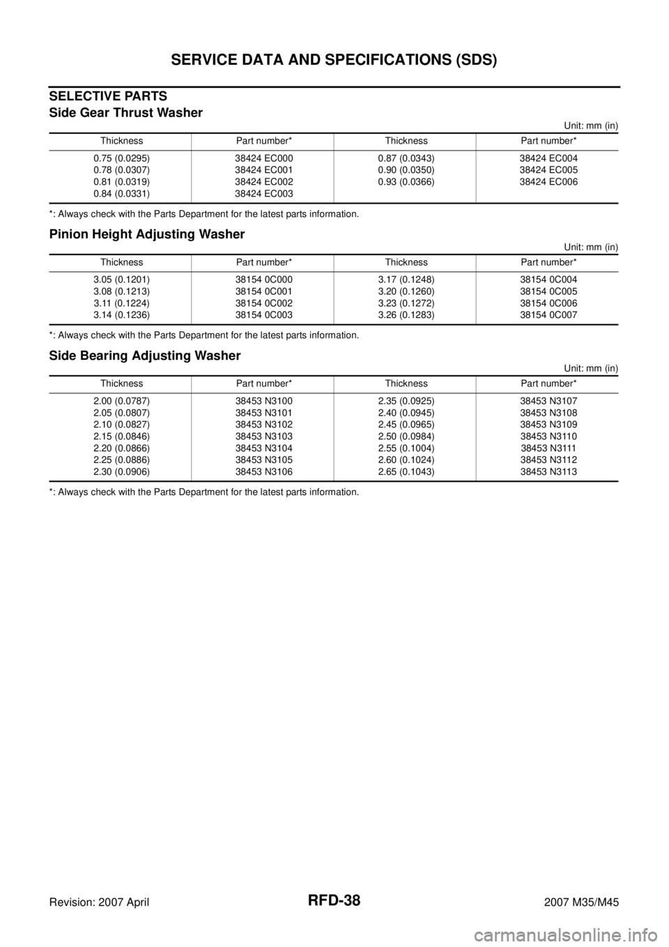
SELECTIVE PARTS
Side Gear Thrust Washer
Unit: mm (in)
*: Always check with the Parts Department for the latest parts information.
Pinion Height Adjusting Washer
Unit: mm (in)
*: Always check with the Parts Department for the latest parts information.
Side Bearing Adjusting Washer
Unit: mm (in)
*: Always check with the Parts Department for the latest parts information.Thickness Part number* Thickness Part number*
0.75 (0.0295)
0.78 (0.0307)
0.81 (0.0319)
0.84 (0.0331)38424 EC000
38424 EC001
38424 EC002
38424 EC0030.87 (0.0343)
0.90 (0.0350)
0.93 (0.0366)38424 EC004
38424 EC005
38424 EC006
Thickness Part number* Thickness Part number*
3.05 (0.1201)
3.08 (0.1213)
3.11 (0.1224)
3.14 (0.1236)38154 0C000
38154 0C001
38154 0C002
38154 0C0033.17 (0.1248)
3.20 (0.1260)
3.23 (0.1272)
3.26 (0.1283)38154 0C004
38154 0C005
38154 0C006
38154 0C007
Thickness Part number* Thickness Part number*
2.00 (0.0787)
2.05 (0.0807)
2.10 (0.0827)
2.15 (0.0846)
2.20 (0.0866)
2.25 (0.0886)
2.30 (0.0906)38453 N3100
38453 N3101
38453 N3102
38453 N3103
38453 N3104
38453 N3105
38453 N31062.35 (0.0925)
2.40 (0.0945)
2.45 (0.0965)
2.50 (0.0984)
2.55 (0.1004)
2.60 (0.1024)
2.65 (0.1043)38453 N3107
38453 N3108
38453 N3109
38453 N3110
38453 N3111
38453 N3112
38453 N3113