Page 4613 of 4647
WW-22
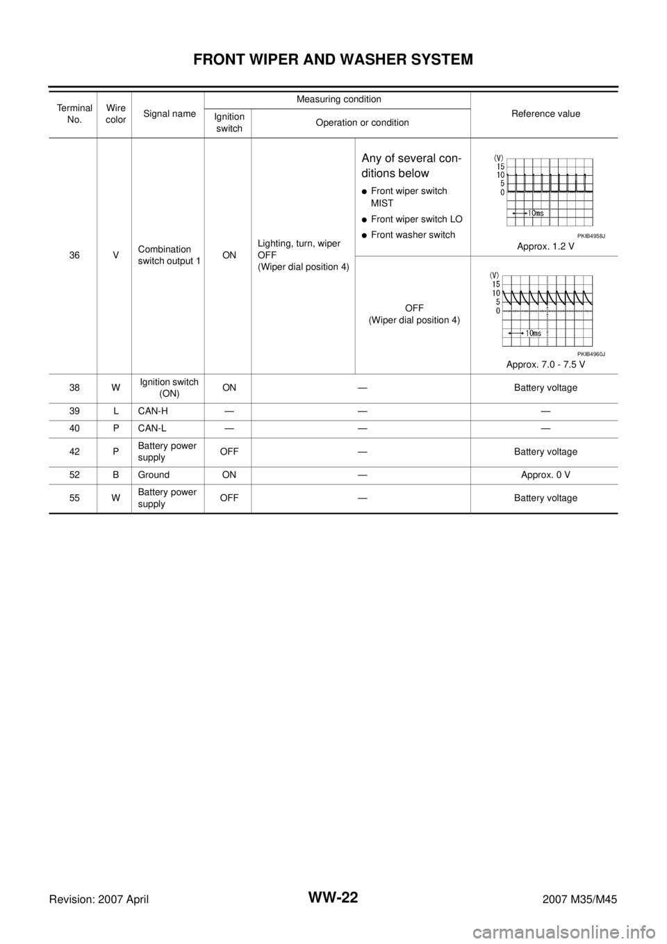
FRONT WIPER AND WASHER SYSTEM
Revision: 2007 April2007 M35/M45
36 VCombination
switch output 1ONLighting, turn, wiper
OFF
(Wiper dial position 4)
Any of several con-
ditions below
�Front wiper switch
MIST
�Front wiper switch LO
�Front washer switch
Approx. 1.2 V
OFF
(Wiper dial position 4)
Approx. 7.0 - 7.5 V
38 WIgnition switch
(ON) ON — Battery voltage
39 L CAN-H — — —
40 P CAN-L — — —
42 PBattery power
supplyOFF — Battery voltage
52 B Ground ON — Approx. 0 V
55 WBattery power
supplyOFF — Battery voltage Te r m i n a l
No.Wire
colorSignal nameMeasuring condition
Reference value
Ignition
switchOperation or conditionPKIB4958J
PKIB4960J
Page 4614 of 4647

FRONT WIPER AND WASHER SYSTEM
WW-23
C
D
E
F
G
H
I
J
L
MA
B
WW
Revision: 2007 April2007 M35/M45
Terminals and Reference Values for IPDM E/RNKS003WI
NOTE:
�During LO operation, terminal No. 32 detects front wiper motor stopping or moving by front wiper auto stop signal.
�During HI operation, terminal No. 32 detects front wiper motor stopping or moving by front wiper auto stop signal that is output from
terminal No. 44 (not from terminal No. 32).
How to Perform Trouble DiagnosesNKS003WJ
1. Confirm the symptoms and customer complaint.
2. Understand operation description and function description. Refer to WW-4, "
System Description" .
3. Perform the Preliminary Check. Refer to WW-24, "
Preliminary Check" .
4. Check symptom and repair or replace the cause of malfunction.
5. Does the front wiper and washer operate normally? If YES, GO TO 6. If NO, GO TO 4.
6. INSPECTION END
Terminal
No.Wire
colorSignal nameMeasuring condition
Reference value
Ignition
switchOperation or condition
19 O High speed signal ON — Battery voltage
23 V Low speed signal ON Wiper switchOFF Approx. 0 V
LO Battery voltage
31 L/B High speed ground ON — Approx. 0 V
32 L/Y
Wiper auto stop signal
NOTEONWiper operating Approx. 0 V
Wiper stopped Battery voltage
35 R Front wiper reverse relay signal ON Wiper switchOFF Battery voltage
HI Approx. 0 V
38 B Ground ON — Approx. 0 V
44 G/LFront washer motor and front wiper
auto stop signal (HI) power supplyON — Battery voltage
49 L CAN-H — — —
50 P CAN-L — — —
51 B Ground ON — Approx. 0 V
Page 4615 of 4647

WW-24
FRONT WIPER AND WASHER SYSTEM
Revision: 2007 April2007 M35/M45
Preliminary CheckNKS003WK
CHECK POWER SUPPLY AND GROUND CIRCUIT
1. CHECK FUSES AND FUSIBLE LINK
Check for blown fuses and fusible link.
Refer to WW-13, "
Wiring Diagram — WIPER —" .
OK or NG
OK >> GO TO 2.
NG >> If fuse or fusible link is blown, be sure to eliminate cause of malfunction before installing new fuse
or fusible link. Refer to PG-3, "
POWER SUPPLY ROUTING CIRCUIT" .
2. CHECK POWER SUPPLY CIRCUIT
1. Turn ignition switch OFF.
2. Disconnect BCM connectors.
3. Check voltage between BCM harness connector and ground.
OK or NG
OK >> GO TO 3.
NG >> Repair harness or connector.
3. CHECK GROUND CIRCUIT
Check continuity between BCM harness connector and ground.
OK or NG
OK >> INSPECTION END
NG >> Repair harness or connector.
Unit Power source Fuse and fusible link No.
BCMBatteryF
21
Ignition switch ON or START 1
Front washer motor, front washer pump and front wiper HI auto
stop signalIgnition switch ON or START 84
Front wiper motor, front wiper low relay, front wiper high relay Battery 73
Front wiper reverse relay Ignition switch ON or START 12
Terminal Ignition switch position
(+)
(-) OFF ON
BCM
connectorTerminal
M1 38
GroundApprox. 0 V Battery voltage
M242 Battery voltage Battery voltage
55 Battery voltage Battery voltage
PKIA7520E
BCM connector Terminal
GroundContinuity
M2 52 Yes
SKIB5125E
Page 4620 of 4647
FRONT WIPER AND WASHER SYSTEM
WW-29
C
D
E
F
G
H
I
J
L
MA
B
WW
Revision: 2007 April2007 M35/M45
4. CHECK CIRCUIT BETWEEN FRONT WIPER MOTOR AND FRONT WIPER REVERSE RELAY
1. Turn ignition switch OFF.
2. Disconnect front wiper motor connector.
3. Remove front wiper reverse relay.
4. Check continuity between front wiper motor harness connector
(A) and front wiper reverse relay harness connector (B).
OK or NG
OK >> GO TO 5.
NG >> Repair harness or connector.
5. CHECK FRONT WIPER REVERSE RELAY
1. Check continuity between front wiper reverse relay terminals.
2. Check continuity between front wiper reverse relay terminals.
OK or NG
OK >> GO TO 6.
NG >> Replace front wiper reverse relay.
AB
Continuity
Connector Terminal Connector Terminal
E271E333 Yes
SKIB4659E
Front wiper reverse relay terminals Continuity
34Yes
SKIB4660E
Front wiper reverse
relay terminalsCondition Continuity
35Applying battery voltage to between
terminals 1 and 2Ye s
No battery voltage No
SKIB4671E
Page 4622 of 4647

FRONT WIPER AND WASHER SYSTEM
WW-31
C
D
E
F
G
H
I
J
L
MA
B
WW
Revision: 2007 April2007 M35/M45
7. CHECK IPDM E/R
With CONSULT-II
1. Connect IPDM E/R connector and front wiper motor connector.
2. Install front wiper reverse relay.
3. Select “IPDM E/R” on CONSULT-II. Select “ACTIVE TEST” on “SELECT DIAG MODE” screen.
4. Select “FRONT WIPER” on “SELECT TEST ITEM” screen.
5. Touch “LO” or “HI” screen.
6. Check voltage between IPDM E/R harness connector and
ground while front wiper (HI, LO) is operating.
Without CONSULT-II
1. Connect IPDM E/R connector and front wiper motor connector.
2. Install front wiper reverse relay.
3. Start up auto active test. Refer to PG-23, "
Auto Active Test" .
4. Check voltage between IPDM E/R harness connector and ground while front wiper (HI, LO) is operating.
OK or NG
OK >> Replace front wiper motor. Refer to WW-44, "Disassembly and Assembly of Front Wiper Drive
Assembly" .
NG >> Replace IPDM E/R. Refer to PG-31, "
Removal and Installation of IPDM E/R" .
Front Wiper Does Not Return to Stop Position (After Front Wiper Operate for 10
Seconds, They Stop for 20 Seconds, and After Repeating the Operations Five
Times, They Become Inoperative)
NKS003WO
CAUTION:
�When auto stop signal has not varied for 10 seconds or longer while IPDM E/R is operating front
wipers, IPDM E/R considers that front wipers are locked, and stops wiper output. That causes this
symptom.
�This status can be checked by “DATA MONITOR” of “IPDM E/R” on which “WIPER PROTECTION”
item shows “BLOCK”.
Terminal
ConditionVoltage
(Approx.) (+)
(-)
IPDM E/R
connectorTerminal
E719
GroundStopped
Battery voltage
HI operation
23Stopped 0 V
LO operation Battery voltage
Terminal
ConditionVoltage
(Approx.) (+)
(-)
IPDM E/R
connectorTerminal
E719
GroundStopped
Battery voltage
HI operation
23Stopped 0 V
LO operation Battery voltage
SKIB4663E
Page 4623 of 4647

WW-32
FRONT WIPER AND WASHER SYSTEM
Revision: 2007 April2007 M35/M45
1. CHECK FRONT WIPER STOP SIGNAL
With CONSULT-II
Select “IPDM E/R” on CONSULT-II. With “DATA MONITOR”, make
sure that “WIP AUTO STOP” turns “ACT P” - “STOP P” linked with
wiper operation.
Without CONSULT-II
GO TO 2.
OK or NG
OK >> Replace IPDM E/R. Refer to PG-31, "Removal and
Installation of IPDM E/R" .
NG >> GO TO 2.
2. CHECK IPDM E/R
Check voltage between IPDM E/R harness connector and ground
while front wiper motor is stopped and while front wiper (HI, LO) is
operating.
OK or NG
OK >> Replace IPDM E/R. Refer to PG-31, "Removal and Installation of IPDM E/R" .
NG >> GO TO 3.
3. CHECK FRONT WIPER AUTO STOP CIRCUIT
1. Turn ignition switch OFF.
2. Disconnect IPDM E/R connector and front wiper motor connector.
3. Check continuity between IPDM E/R harness connector (A) and
front wiper motor harness connector (B).
4. Check continuity between IPDM E/R harness connector (A) and
ground.
OK or NG
OK >> Replace front wiper motor. Refer to WW-44, "Disassembly and Assembly of Front Wiper Drive
Assembly" .
NG >> Repair harness or connector.
PKIA7614E
Terminal
ConditionVoltage
(Approx.) (+)
(-)
IPDM E/R
connectorTerminal
E7 32 GroundWiper stopped Battery voltage
Wiper operating 0 V
SKIB4665E
AB
Continuity
Connector Terminal Connector Terminal
E7 32 E27 5 Yes
A
GroundContinuity
Connector Terminal
E7 32 No
SKIB4664E
Page 4624 of 4647

FRONT WIPER AND WASHER SYSTEM
WW-33
C
D
E
F
G
H
I
J
L
MA
B
WW
Revision: 2007 April2007 M35/M45
Front Wiper Does Not Return to Stop Position When Front Wiper Motor Oper-
ates at Low Speed (After Front Wiper Operate for 10 Seconds, They Stop for 20
Seconds, and After Repeating the Operations Five Times, They Become Inoper-
ative)
NKS003WP
CAUTION:
�When auto stop signal has not varied for 10 seconds or longer while IPDM E/R is operating front
wipers, IPDM E/R considers that front wipers are locked, and stops wiper output. That causes this
symptom.
�This status can be checked by “DATA MONITOR” of “IPDM E/R” on which “WIPER PROTECTION”
item shows “BLOCK”.
1. CHECK FRONT WIPER STOP SIGNAL
With CONSULT-II
Select “IPDM E/R” on CONSULT-II. With “DATA MONITOR”, make
sure that “WIP AUTO STOP” turns “ACT P” - “STOP P” linked with
wiper LO operation.
Without CONSULT-II
GO TO 2.
OK or NG
OK >> Replace IPDM E/R. Refer to PG-31, "Removal and
Installation of IPDM E/R" .
NG >> GO TO 2.
2. CHECK IPDM E/R
Check voltage between IPDM E/R harness connector and ground
while front wiper motor is stopped and while front wiper LO is operat-
ing.
OK or NG
OK >> Replace IPDM E/R. Refer to PG-31, "Removal and Installation of IPDM E/R" .
NG >> GO TO 3.
3. CHECK CIRCUIT BETWEEN FRONT WIPER MOTOR AND GROUND
1. Turn ignition switch OFF.
2. Disconnect front wiper motor connector.
3. Check continuity between front wiper motor harness connector
and ground.
OK or NG
OK >> Replace front wiper motor. Refer to WW-44, "Disassem-
bly and Assembly of Front Wiper Drive Assembly" .
NG >> Repair harness or connector.
PKIA7614E
Terminal
ConditionVoltage
(Approx.) (+)
(-)
IPDM E/R
connectorTe r m i n a l
E7 32 GroundWiper stopped Battery voltage
Wiper operating 0 V
SKIB4665E
Front wiper motor
connectorTerminal
GroundContinuity
E27 6 Yes
SKIB4667E
Page 4625 of 4647

WW-34
FRONT WIPER AND WASHER SYSTEM
Revision: 2007 April2007 M35/M45
Front Wiper Does Not Return to Stop Position When Front Wiper Motor Oper-
ates at HIGH Speed (After Front Wiper Operate for 10 Seconds, They Stop for 20
Seconds, and After Repeating the Operations Five Times, They Become Inoper-
ative)
NKS003WQ
CAUTION:
�When auto stop signal has not varied for 10 seconds or longer while IPDM E/R is operating front
wipers, IPDM E/R considers that front wipers are locked, and stops wiper output. That causes this
symptom.
�This status can be checked by “DATA MONITOR” of “IPDM E/R” on which “WIPER PROTECTION”
item shows “BLOCK”.
1. CHECK FRONT WIPER STOP SIGNAL
With CONSULT-ll
Select “IPDM E/R” on CONSULT-II. With “DATA MONITOR”, make
sure that “WIP AUTO STOP” turns “ACT P” - “STOP P” linked with
wiper HI operation.
Without CONSULT-ll
GO TO 2.
OK or NG
OK >> Replace IPDM E/R. Refer to PG-31, "Removal and
Installation of IPDM E/R" .
NG >> GO TO 2.
2. CHECK IPDM E/R
1. Turn ignition switch OFF.
2. Connect IPDM E/R connector and front wiper motor connector.
3. Turn ignition switch ON.
4. Check voltage between IPDM E/R harness connector and
ground while front wiper motor is stopped and while front wiper
HI is operating.
OK or NG
OK >> Replace IPDM E/R. Refer to PG-31, "Removal and Installation of IPDM E/R" .
NG >> GO TO 3.
PKIA7614E
Te r m i n a l
ConditionVoltage
(Approx.) (+)
(-)
IPDM E/R
connectorTerminal
E7 32 GroundWiper stopped Battery voltage
Wiper operating 0 V
SKIB4665E