Page 2301 of 4647
![INFINITI M35 2007 Factory Service Manual EC-772
[VK45DE]
ON BOARD DIAGNOSTIC (OBD) SYSTEM
Revision: 2007 April2007 M35/M45
–Test values
Actual work procedures are explained using a DTC as an example. Be careful so that not only the DTC, bu](/manual-img/42/57024/w960_57024-2300.png "INFINITI M35 2007 Factory Service Manual EC-772
[VK45DE]
ON BOARD DIAGNOSTIC (OBD) SYSTEM
Revision: 2007 April2007 M35/M45
–Test values
Actual work procedures are explained using a DTC as an example. Be careful so that not only the DTC, bu")
EC-772
[VK45DE]
ON BOARD DIAGNOSTIC (OBD) SYSTEM
Revision: 2007 April2007 M35/M45
–Test values
Actual work procedures are explained using a DTC as an example. Be careful so that not only the DTC, but all
of the data listed above, are cleared from the ECM memory during work procedures.
Malfunction Indicator Lamp (MIL)NBS005A4
DESCRIPTION
The MIL is located on the instrument panel.
1. The MIL will light up when the ignition switch is turned ON with-
out the engine running. This is a bulb check.
If the MIL does not light up, refer to DI-39, "
WARNING LAMPS" ,
or see EC-1438, "
MIL AND DATA LINK CONNECTOR" .
2. When the engine is started, the MIL should go off.
If the MIL remains on, the on board diagnostic system has
detected an engine system malfunction.
ON BOARD DIAGNOSTIC SYSTEM FUNCTION
The on board diagnostic system has the following three functions.
When there is an open circuit on MIL circuit, the ECM cannot warn the driver by lighting up MIL when there is
malfunction on engine control system.
Therefore, when electrical controlled throttle and part of ECM related diagnoses are continuously detected as
NG for 5 trips, ECM warns the driver that engine control system malfunctions and MIL circuit is open by means
of operating fail-safe function.
The fail-safe function also operates when above diagnoses except MIL circuit are detected and demands the
driver to repair the malfunction.
SEF217U
Diagnostic Test
ModeKEY and ENG.
Sta tusFunction Explanation of Function
Mode I Ignition switch in
ON position
Engine stoppedBULB CHECK This function checks the MIL bulb for damage (blown,
open circuit, etc.).
If the MIL does not come on, check MIL circuit.
Engine running MALFUNCTION
WARNINGThis is a usual driving condition. When a malfunction is
detected twice in two consecutive driving cycles (two trip
detection logic), the MIL will light up to inform the driver
that a malfunction has been detected.
The following malfunctions will light up or blink the MIL in
the 1st trip.
�Misfire (Possible three way catalyst damage)
�One trip detection diagnoses
Mode II Ignition switch in
ON position
Engine stoppedSELF-DIAGNOSTIC
RESULTSThis function allows DTCs and 1st trip DTCs to be read.
Engine operating condition in fail-safe mode Engine speed will not rise more than 2,500 rpm due to the fuel cut
Page 2302 of 4647
![INFINITI M35 2007 Factory Service Manual ON BOARD DIAGNOSTIC (OBD) SYSTEM
EC-773
[VK45DE]
C
D
E
F
G
H
I
J
K
L
MA
EC
Revision: 2007 April2007 M35/M45
MIL Flashing Without DTC
When any SRT codes are not set, MIL may flash without DTC. For the](/manual-img/42/57024/w960_57024-2301.png "INFINITI M35 2007 Factory Service Manual ON BOARD DIAGNOSTIC (OBD) SYSTEM
EC-773
[VK45DE]
C
D
E
F
G
H
I
J
K
L
MA
EC
Revision: 2007 April2007 M35/M45
MIL Flashing Without DTC
When any SRT codes are not set, MIL may flash without DTC. For the")
ON BOARD DIAGNOSTIC (OBD) SYSTEM
EC-773
[VK45DE]
C
D
E
F
G
H
I
J
K
L
MA
EC
Revision: 2007 April2007 M35/M45
MIL Flashing Without DTC
When any SRT codes are not set, MIL may flash without DTC. For the details, refer to EC-765, "How to Dis-
play SRT Status" .
HOW TO SWITCH DIAGNOSTIC TEST MODE
NOTE:
�It is better to count the time accurately with a clock.
�It is impossible to switch the diagnostic mode when an accelerator pedal position sensor circuit
has a malfunction.
�Always ECM returns to Diagnostic Test Mode I after ignition switch is turned OFF.
How to Set Diagnostic Test Mode II (Self-diagnostic Results)
1. Confirm that accelerator pedal is fully released, turn ignition switch ON and wait 3 seconds.
2. Repeat the following procedure quickly five times within 5 seconds.
a. Fully depress the accelerator pedal.
b. Fully release the accelerator pedal.
3. Wait 7 seconds, fully depress the accelerator pedal and keep it for approx. 10 seconds until the MIL starts
blinking.
NOTE:
Do not release the accelerator pedal for 10 seconds if MIL may start blinking on the halfway of this
10 seconds. This blinking is displaying SRT status and is continued for another 10 seconds. For
the details, refer to EC-765, "
How to Display SRT Status" .
4. Fully release the accelerator pedal.
ECM has entered to Diagnostic Test Mode II (Self-diagnostic results).
NOTE:
Wait until the same DTC (or 1st trip DTC) appears to confirm all DTCs certainly.
How to Erase Diagnostic Test Mode II (Self-diagnostic Results)
1. Set ECM in Diagnostic Test Mode II (Self-diagnostic results). Refer to EC-773, "How to Set Diagnostic
Test Mode II (Self-diagnostic Results)" .
2. Fully depress the accelerator pedal and keep it for more than 10 seconds.
The emission-related diagnostic information has been erased from the backup memory in the ECM.
3. Fully release the accelerator pedal, and confirm the DTC 0000 is displayed.
DIAGNOSTIC TEST MODE I — BULB CHECK
In this mode, the MIL on the instrument panel should stay ON. If it remains OFF, check the bulb. Refer to DI-
39, "WARNING LAMPS" or see EC-1438, "MIL AND DATA LINK CONNECTOR" .
DIAGNOSTIC TEST MODE I — MALFUNCTION WARNING
This DTC number is clarified in Diagnostic Test Mode II (SELF-DIAGNOSTIC RESULTS)
DIAGNOSTIC TEST MODE II — SELF-DIAGNOSTIC RESULTS
In this mode, the DTC and 1st trip DTC are indicated by the number of blinks of the MIL as shown below.
PBIB0092E
MIL Condition
ON When the malfunction is detected.
OFF No malfunction.
Page 2311 of 4647
![INFINITI M35 2007 Factory Service Manual EC-782
[VK45DE]
BASIC SERVICE PROCEDURE
Revision: 2007 April2007 M35/M45
6. PERFORM IDLE AIR VOLUME LEARNING
Refer to EC-788, "
Idle Air Volume Learning" .
Is Idle Air Volume Learning carried out succ](/manual-img/42/57024/w960_57024-2310.png "INFINITI M35 2007 Factory Service Manual EC-782
[VK45DE]
BASIC SERVICE PROCEDURE
Revision: 2007 April2007 M35/M45
6. PERFORM IDLE AIR VOLUME LEARNING
Refer to EC-788, \"
Idle Air Volume Learning\" .
Is Idle Air Volume Learning carried out succ")
EC-782
[VK45DE]
BASIC SERVICE PROCEDURE
Revision: 2007 April2007 M35/M45
6. PERFORM IDLE AIR VOLUME LEARNING
Refer to EC-788, "
Idle Air Volume Learning" .
Is Idle Air Volume Learning carried out successfully?
Ye s o r N o
Yes >> GO TO 7.
No >> 1. Follow the instruction of Idle Air Volume Learning.
2. GO TO 4.
7. CHECK TARGET IDLE SPEED AGAIN
With CONSULT-II
1. Start engine and warm it up to normal operating temperature.
2. Read idle speed in “DATA MONITOR” mode with CONSULT-II.
Refer to EC-785, "
IDLE SPEED" .
Without CONSULT-II
1. Start engine and warm it up to normal operating temperature.
2. Check idle speed.
Refer to EC-785, "
IDLE SPEED" .
OK or NG
OK >> GO TO 10.
NG >> GO TO 8.
8. DETECT MALFUNCTIONING PART
Check the Following.
�Check camshaft position sensor (PHASE) and circuit. Refer to EC-1082, "DTC P0340 CAMSHAFT POSI-
TION (CMP) SENSOR (PHASE)" .
�Check crankshaft position sensor (POS) and circuit. Refer to EC-1075, "DTC P0335 CKP SENSOR
(POS)" .
OK or NG
OK >> GO TO 9.
NG >> 1. Repair or replace.
2. GO TO 4.
9. CHECK ECM FUNCTION
1. Substitute another known-good ECM to check ECM function. (ECM may be the cause of an incident, but
this is a rare case.)
2. Perform initialization of IVIS (NATS) system and registration of all IVIS (NATS) ignition key IDs. Refer to
BL-248, "
ECM Re-Communicating Function" .
>> GO TO 4. 650 ± 50 rpm (in P or N position)
SEF174Y
650 ± 50 rpm (in P or N position)
Page 2312 of 4647
BASIC SERVICE PROCEDURE
EC-783
[VK45DE]
C
D
E
F
G
H
I
J
K
L
MA
EC
Revision: 2007 April2007 M35/M45
10. CHECK IGNITION TIMING
1. Run engine at idle.
2. Check ignition timing with a timing light.
Refer to EC-785, "
IGNITION TIMING" .
–Timing indicator (1)
OK or NG
OK >> GO TO 19.
NG >> GO TO 11.
11 . PERFORM ACCELERATOR PEDAL RELEASED POSITION LEARNING
1. Stop engine.
2. Perform EC-788, "
Accelerator Pedal Released Position Learning" .
>> GO TO 12.
12. PERFORM THROTTLE VALVE CLOSED POSITION LEARNING
Perform EC-788, "
Throttle Valve Closed Position Learning" .
>> GO TO 13.
13. PERFORM IDLE AIR VOLUME LEARNING
Refer to EC-788, "
Idle Air Volume Learning" .
Is Idle Air Volume Learning carried out successfully?
Ye s o r N o
Ye s > > G O T O 1 4 .
No >> 1. Follow the instruction of Idle Air Volume Learning.
2. GO TO 4. 12 ± 5° BTDC (in P or N position)
PBIB2719E
Page 2313 of 4647
EC-784
[VK45DE]
BASIC SERVICE PROCEDURE
Revision: 2007 April2007 M35/M45
14. CHECK TARGET IDLE SPEED AGAIN
With CONSULT-II
1. Start engine and warm it up to normal operating temperature.
2. Read idle speed in “DATA MONITOR” mode with CONSULT-II.
Refer to EC-785, "
IDLE SPEED" .
Without CONSULT-II
1. Start engine and warm it up to normal operating temperature.
2. Check idle speed.
Refer to EC-785, "
IDLE SPEED" .
OK or NG
OK >> GO TO 15.
NG >> GO TO 17.
15. CHECK IGNITION TIMING AGAIN
1. Run engine at idle.
2. Check ignition timing with a timing light.
Refer to EC-785, "
IGNITION TIMING" .
–Timing indicator (1)
OK or NG
OK >> GO TO 19.
NG >> GO TO 16.
16. CHECK TIMING CHAIN INSTALLATION
Check timing chain installation. Refer to EM-203, "
TIMING CHAIN" .
OK or NG
OK >> GO TO 17.
NG >> 1. Repair the timing chain installation.
2. GO TO 4. 650 ± 50 rpm (in P or N position)
SEF174Y
650 ± 50 rpm (in P or N position)
12 ± 5° BTDC (in P or N position)
PBIB2719E
Page 2314 of 4647
![INFINITI M35 2007 Factory Service Manual BASIC SERVICE PROCEDURE
EC-785
[VK45DE]
C
D
E
F
G
H
I
J
K
L
MA
EC
Revision: 2007 April2007 M35/M45
17. DETECT MALFUNCTIONING PART
Check the following.
�Check camshaft position sensor (PHASE) and circu](/manual-img/42/57024/w960_57024-2313.png "INFINITI M35 2007 Factory Service Manual BASIC SERVICE PROCEDURE
EC-785
[VK45DE]
C
D
E
F
G
H
I
J
K
L
MA
EC
Revision: 2007 April2007 M35/M45
17. DETECT MALFUNCTIONING PART
Check the following.
�Check camshaft position sensor (PHASE) and circu")
BASIC SERVICE PROCEDURE
EC-785
[VK45DE]
C
D
E
F
G
H
I
J
K
L
MA
EC
Revision: 2007 April2007 M35/M45
17. DETECT MALFUNCTIONING PART
Check the following.
�Check camshaft position sensor (PHASE) and circuit. Refer to EC-1082, "DTC P0340 CAMSHAFT POSI-
TION (CMP) SENSOR (PHASE)" .
�Check crankshaft position sensor (POS) and circuit. Refer to EC-1075, "DTC P0335 CKP SENSOR
(POS)" .
OK or NG
OK >> GO TO 18.
NG >> 1. Repair or replace.
2. GO TO 4.
18. CHECK ECM FUNCTION
1. Substitute another known-good ECM to check ECM function. (ECM may be the cause of an incident, but
this is a rare case.)
2. Perform initialization of IVIS (NATS) system and registration of all IVIS (NATS) ignition key IDs. Refer to
BL-248, "
ECM Re-Communicating Function" .
>> GO TO 4.
19. INSPECTION END
Did you replace ECM, referring this Basic Inspection procedure?
Ye s o r N o
Ye s > > 1 . P e r f o r m EC-787, "VIN Registration" .
2.INSPECTION END
No >>INSPECTION END
Idle Speed and Ignition Timing CheckNBS005A7
IDLE SPEED
With CONSULT-II
Check idle speed in “DATA MONITOR” mode with CONSULT-II.
With GST
Check idle speed with GST.
IGNITION TIMING
Any of following two methods may be used.
SEF058Y
Page 2315 of 4647
EC-786
[VK45DE]
BASIC SERVICE PROCEDURE
Revision: 2007 April2007 M35/M45
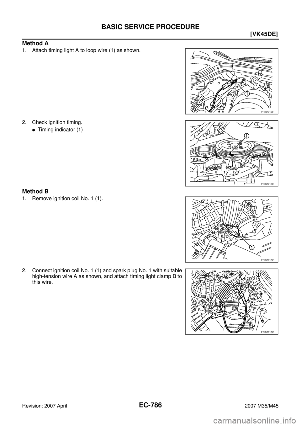
Method A
1. Attach timing light A to loop wire (1) as shown.
2. Check ignition timing.
�Timing indicator (1)
Method B
1. Remove ignition coil No. 1 (1).
2. Connect ignition coil No. 1 (1) and spark plug No. 1 with suitable
high-tension wire A as shown, and attach timing light clamp B to
this wire.
PBIB2717E
PBIB2719E
PBIB2716E
PBIB2718E
Page 2316 of 4647
![INFINITI M35 2007 Factory Service Manual BASIC SERVICE PROCEDURE
EC-787
[VK45DE]
C
D
E
F
G
H
I
J
K
L
MA
EC
Revision: 2007 April2007 M35/M45
3. Check ignition timing.
�Timing indicator (1)
Procedure After Replacing ECMNBS005SH
When replacing](/manual-img/42/57024/w960_57024-2315.png "INFINITI M35 2007 Factory Service Manual BASIC SERVICE PROCEDURE
EC-787
[VK45DE]
C
D
E
F
G
H
I
J
K
L
MA
EC
Revision: 2007 April2007 M35/M45
3. Check ignition timing.
�Timing indicator (1)
Procedure After Replacing ECMNBS005SH
When replacing")
BASIC SERVICE PROCEDURE
EC-787
[VK45DE]
C
D
E
F
G
H
I
J
K
L
MA
EC
Revision: 2007 April2007 M35/M45
3. Check ignition timing.
�Timing indicator (1)
Procedure After Replacing ECMNBS005SH
When replacing ECM, the following procedure must be performed.
1. Perform initialization of IVIS (NATS) system and registration of all IVIS (NATS) ignition key IDs.
Refer to BL-248, "
ECM Re-Communicating Function" .
2. Perform EC-787, "
VIN Registration" .
3. Perform EC-788, "
Accelerator Pedal Released Position Learning" .
4. Perform EC-788, "
Throttle Valve Closed Position Learning" .
5. Perform EC-788, "
Idle Air Volume Learning" .
VIN RegistrationNBS005A9
DESCRIPTION
VIN Registration is an operation to registering VIN in ECM. It must be performed each time ECM is replaced.
NOTE:
Accurate VIN which is registered in ECM may be required for Inspection & Maintenance (I/M).
OPERATION PROCEDURE
With CONSULT-II
1. Check the VIN of the vehicle and note it. Refer to GI-48, "IDENTIFICATION INFORMATION" .
2. Turn ignition switch ON and engine stopped.
3. Select “VIN REGISTRATION” in “WORK SUPPORT” mode.
4. Follow the instruction of CONSULT-II display.
SEF166Y
PBIB2719E
PBIB2242E
![INFINITI M35 2007 Factory Service Manual BASIC SERVICE PROCEDURE
EC-783
[VK45DE]
C
D
E
F
G
H
I
J
K
L
MA
EC
Revision: 2007 April2007 M35/M45
10. CHECK IGNITION TIMING
1. Run engine at idle.
2. Check ignition timing with a timing light.
Refer](/manual-img/42/57024/w960_57024-2311.png "INFINITI M35 2007 Factory Service Manual BASIC SERVICE PROCEDURE
EC-783
[VK45DE]
C
D
E
F
G
H
I
J
K
L
MA
EC
Revision: 2007 April2007 M35/M45
10. CHECK IGNITION TIMING
1. Run engine at idle.
2. Check ignition timing with a timing light.
Refer")
![INFINITI M35 2007 Factory Service Manual EC-784
[VK45DE]
BASIC SERVICE PROCEDURE
Revision: 2007 April2007 M35/M45
14. CHECK TARGET IDLE SPEED AGAIN
With CONSULT-II
1. Start engine and warm it up to normal operating temperature.
2. Read idle](/manual-img/42/57024/w960_57024-2312.png "INFINITI M35 2007 Factory Service Manual EC-784
[VK45DE]
BASIC SERVICE PROCEDURE
Revision: 2007 April2007 M35/M45
14. CHECK TARGET IDLE SPEED AGAIN
With CONSULT-II
1. Start engine and warm it up to normal operating temperature.
2. Read idle")