2007 INFINITI FX35 replace front turn signal bulb
[x] Cancel search: replace front turn signal bulbPage 3457 of 4366
LT-1
LIGHTING SYSTEM
K ELECTRICAL
CONTENTS
C
D E
F
G H
I
J
L
M
SECTION LT
A
B
LT
Revision: 2006 July 2007 FX35/FX45
LIGHTING SYSTEM
PRECAUTIONS .......................................................... 5
Precautions for Supplemental Restraint System
(SRS) “AIR BAG” and “SEAT BELT PRE-TEN-
SIONER” ............................................................. ..... 5
General Precautions for Service Operations ....... ..... 5
HEADLAMP - XENON TYPE - .............................. ..... 6
Component Parts and Harness Connector Location ..... 6
System Description ............................................. ..... 6
OUTLINE .......................................................... ..... 6
HEADLAMP OPERATION ............................... ..... 7
COMBINATION SWITCH READING FUNCTION ..... 8
EXTERIOR LAMP BATTERY SAVER CONTROL ..... 8
AUTO LIGHT OPERATION (IF EQUIPPED) .... ..... 8
VEHICLE SECURITY SYSTEM ....................... ..... 8
XENON HEADLAMP ........................................ ..... 8
CAN Communication System Description ........... ..... 8
CAN Communication Unit ................................... ..... 8
Schematic ........................................................... ..... 9
Wiring Diagram — H/LAMP — ............................ ... 10
Terminals and Reference Values for BCM .......... ... 14
Terminals and Reference Values for IPDM E/R .. ... 16
How to Proceed With Trouble Diagnosis ............. ... 16
Preliminary Check ............................................... ... 16
CHECK POWER SUPPLY AND GROUND CIR-
CUIT ................................................................. ... 16
CONSULT-II Functions (BCM) ............................ ... 18
CONSULT-II BASIC OPERATION .................... ... 18
WORK SUPPORT ............................................ ... 18
DATA MONITOR .............................................. ... 18
ACTIVE TEST .................................................. ... 20
CONSULT-II Functions (IPDM E/R) .................... ... 20
CONSULT-II BASIC OPERATION .................... ... 20
DATA MONITOR .............................................. ... 20
ACTIVE TEST .................................................. ... 21
Headlamp Does Not Change To High Beam (Both
Sides) .................................................................. ... 22
Headlamp Does Not Change To High Beam (One
Side) .................................................................... ... 24
Headlamp Low Beam Does Not Illuminate (Both
Sides) .................................................................. ... 25 Headlamp Low Beam Does Not Illuminate (One
Side) .................................................................... ... 27
Headlamp RH Low Beam and High Beam Does Not
Illuminate ............................................................. ... 29
Headlamp LH Low Beam and High Beam Does Not
Illuminate ............................................................. ... 29
Headlamps Do Not Turn OFF .............................. ... 30
General Information for Xenon Headlamp Trouble
Diagnosis ............................................................. ... 32
Caution: ............................................................... ... 32
Xenon Headlamp Trouble Diagnosis ................... ... 32
Aiming Adjustment ............................................... ... 33
PREPARATION BEFORE ADJUSTING ........... ... 33
LOW BEAM AND HIGH BEAM ........................ ... 33
ADJUSTMENT USING AN ADJUSTMENT
SCREEN (LIGHT/DARK BORDERLINE) ......... ... 34
Bulb Replacement ............................................... ... 34
HEADLAMP HIGH/LOW BEAM ....................... ... 34
DAYTIME/PARKING LAMP .............................. ... 35
FRONT TURN SIGNAL LAMP ......................... ... 35
FRONT SIDE MARKER LAMP ........................ ... 35
Removal and Installation ..................................... ... 35
REMOVAL ........................................................ ... 35
INSTALLATION ................................................ ... 36
Disassembly and Assembly ................................. ... 36
DISASSEMBLY ................................................ ... 36
ASSEMBLY ...................................................... ... 36
DAYTIME LIGHT SYSTEM .................................... ... 38
Component Parts and Harness Connector Location ... 38
System Description .............................................. ... 38
OUTLINE .......................................................... ... 38
DAYTIME LIGHT OPERATION ........................ ... 39
COMBINATION SWITCH READING FUNCTION ... 39
AUTO LIGHT OPERATION .............................. ... 39
CAN Communication System Description ........... ... 39
CAN Communication Unit .................................... ... 39
Schematic ............................................................ ... 40
Wiring Diagram — DTRL — ................................ ... 41
Terminals and Reference Values for BCM ........... ... 45
How to Proceed With Trouble Diagnosis ............. ... 47
Page 3458 of 4366

LT-2Revision: 2006 July 2007 FX35/FX45
Preliminary Check ...............................................
... 48
CHECK POWER SUPPLY AND GROUND CIR-
CUIT ................................................................. ... 48
INSPECTION PARKING BRAKE SWITCH CIR-
CUIT ................................................................. ... 49
CONSULT-II Functions (BCM) ............................. ... 50
CONSULT-II BASIC OPERATION .................... ... 50
DATA MONITOR ............................................... ... 50
ACTIVE TEST .................................................. ... 51
Daytime Light Control Does Not Operate Properly ... 52
Aiming Adjustment ............................................... ... 54
Bulb Replacement ............................................... ... 54
Removal and Installation ..................................... ... 54
Disassembly and Assembly ................................. ... 54
AUTO LIGHT SYSTEM .......................................... ... 55
Component Parts and Harness Connector Location ... 55
System Description .............................................. ... 55
OUTLINE .......................................................... ... 55
COMBINATION SWITCH READING FUNCTION ... 56
DELAY TIMER FUNCTION .............................. ... 56
CAN Communication System Description ........... ... 56
CAN Communication Unit .................................... ... 56
Major Components and Functions ....................... ... 56
Schematic ............................................................ ... 57
Wiring Diagram — AUTO/L — ............................. ... 58
Terminals and Reference Values for BCM ........... ... 61
Terminals and Reference Values for IPDM E/R ... ... 63
How to Proceed With Trouble Diagnosis ............. ... 63
Preliminary Check ............................................... ... 64
SETTING CHANGE FUNCTIONS .................... ... 64
CHECK POWER SUPPLY AND GROUND CIR-
CUIT ................................................................. ... 64
CONSULT-II Functions (BCM) ............................. ... 66
CONSULT-II BASIC OPERATION .................... ... 66
WORK SUPPORT ............................................ ... 66
DATA MONITOR ............................................... ... 66
ACTIVE TEST .................................................. ... 68
CONSULT-II Functions (IPDM E/R) ..................... ... 68
CONSULT-II BASIC OPERATION .................... ... 68
DATA MONITOR ............................................... ... 68
ACTIVE TEST .................................................. ... 69
Symptom Chart .................................................... ... 69
Lighting Switch Inspection ................................... ... 70
Optical sensor System Inspection ....................... ... 70
Removal and Installation of Optical Sensor ......... ... 72
REMOVAL ........................................................ ... 72
INSTALLATION ................................................. ... 72
HEADLAMP AIMING CONTROL ........................... ... 73
Schematic ............................................................ ... 73
Wiring Diagram — H/AIM — ................................ ... 74
Removal and Installation ..................................... ... 77
REMOVAL ........................................................ ... 77
INSTALLATION ................................................. ... 77
Switch Circuit Inspection ..................................... ... 77
FRONT FOG LAMP ............................................... ... 78
Component Parts and Harness Connector Location ... 78
System Description .............................................. ... 78
OUTLINE .......................................................... ... 78 FRONT FOG LAMP OPERATION ....................
... 79
COMBINATION SWITCH READING FUNCTION ... 79
EXTERIOR LAMP BATTERY SAVER CONTROL ... 79
CAN Communication System Description ........... ... 79
CAN Communication Unit .................................... ... 79
Wiring Diagram — F/FOG — ............................... ... 80
Terminals and Reference Values for BCM ........... ... 82
Terminals and Reference Values for IPDM E/R ... ... 83
How to Proceed With Trouble Diagnosis ............. ... 83
Preliminary Check ................................................ ... 83
CHECK POWER SUPPLY AND GROUND CIR-
CUIT .................................................................. ... 83
CONSULT-II Functions (BCM) ............................. ... 84
CONSULT-II Functions (IPDM E/R) ..................... ... 84
Front Fog Lamps Do Not Illuminate (Both Sides) ... 85
Front Fog Lamp Does Not Illuminate (One Side) . ... 87
Aiming Adjustment ............................................... ... 88
Bulb Replacement ................................................ ... 89
Removal and Installation ...................................... ... 89
REMOVAL ......................................................... ... 89
INSTALLATION ................................................. ... 89
TURN SIGNAL AND HAZARD WARNING LAMPS ... 90
Component Parts and Harness Connector Location ... 90
System Description .............................................. ... 90
OUTLINE .......................................................... ... 90
TURN SIGNAL OPERATION ............................ ... 91
HAZARD LAMP OPERATION .......................... ... 91
REMOTE CONTROL ENTRY SYSTEM OPER-
ATION ............................................................... ... 92
COMBINATION SWITCH READING FUNCTION ... 92
CAN Communication System Description ........... ... 92
CAN Communication Unit .................................... ... 92
Schematic ............................................................ ... 93
Wiring Diagram — TURN — ................................ ... 94
Terminals and Reference Values for BCM ........... ... 97
Terminals and Reference Value for Rear Combina-
tion Lamp Control Unit ......................................... ... 98
How to Proceed With Trouble Diagnosis ............. .100
Preliminary Check ................................................ .100
CHECK POWER SUPPLY AND GROUND CIR-
CUIT .................................................................. .100
CONSULT-II Functions (BCM) ............................. .102
CONSULT-II BASIC OPERATION .................... .102
DATA MONITOR ............................................... .102
ACTIVE TEST ................................................... .102
Turn Signal Lamps Do Not Operate ..................... .103
Rear Turn Signal Lamp Does Not Operate .......... .105
Hazard Warning Lamp Does Not Operate But Turn
Signal Lamp Operate ........................................... .106
Bulb Replacement (Front Turn Signal Lamp) ....... .108
Bulb Replacement (Rear Turn Signal Lamp) ....... .108
Removal and Installation of Front Turn Signal Lamp .108
Removal and Installation of Rear Turn Signal Lamp .108
Removal and Installation of Rear Combination
Lamp Control Unit ................................................ .108
REMOVAL ......................................................... .108
INSTALLATION ................................................. .108
Page 3459 of 4366
LT-3
C
D E
F
G H
I
J
L
M A
B
LT
Revision: 2006 July 2007 FX35/FX45
LIGHTING AND TURN SIGNAL SWITCH .............
. 109
Removal and Installation ..................................... . 109
REMOVAL ........................................................ . 109
INSTALLATION ................................................ . 109
HAZARD SWITCH ................................................. ..110
Removal and Installation ..................................... .. 110
REMOVAL ........................................................ .. 110
INSTALLATION ................................................ .. 110
COMBINATION SWITCH ....................................... .. 111
Wiring Diagram — COMBSW — ......................... . . 111
Combination Switch Reading Function ............... .. 112
Terminals and Reference Values for BCM .......... .. 112
CONSULT-II Functions (BCM) ............................ .. 117
CONSULT-II BASIC OPERATION .................... .. 117
DATA MONITOR .............................................. .. 117
Combination Switch Inspection ........................... .. 118
Removal and Installation ..................................... . 120
STOP LAMP .......................................................... . 121
Component Parts and Harness Connector Location . 121
System Description ............................................. . 121
Schematic ........................................................... . 122
Wiring Diagram — STOP/L — ............................. . 123
Terminals and Reference Value for Rear Combina-
tion Lamp Control Unit ........................................ . 126
Stop Lamp Does Not Operate ............................. . 126
High-Mounted Stop Lamp ................................... . 128
BULB REPLACEMENT, REMOVAL AND
INSTALLATION ................................................ . 128
Stop Lamp ........................................................... . 128
BULB REPLACEMENT .................................... . 128
REMOVAL AND INSTALLATION ..................... . 128
Rear Combination Lamp Control Unit ................. . 128
REMOVAL AND INSTALLATION ..................... . 128
BACK-UP LAMP ................................................... . 129
Wiring Diagram — BACK/L — ............................ . 129
Bulb Replacement ............................................... . 130
Removal and Installation ..................................... . 130
PARKING, LICENSE PLATE AND TAIL LAMPS .. . 131
Component Parts and Harness Connector Location . 131
System Description ............................................. . 131
OUT LINE ......................................................... . 131
OPERATION BY LIGHTING SWITCH ............. . 132
COMBINATION SWITCH READING FUNCTION . 133
EXTERIOR LAMP BATTERY SAVER CONTROL . 133
CAN Communication System Description ........... . 133
CAN Communication Unit ................................... . 133
Schematic ........................................................... . 134
Wiring Diagram — TAIL/L — ............................... . 135
Terminals and Reference Values for BCM .......... . 140
Terminals and Reference Values for IPDM E/R .. . 141
Terminals and Reference Value for Rear Combina-
tion Lamp Control Unit ........................................ . 141
How to Proceed With Trouble Diagnosis ............. . 141
Preliminary Check ............................................... . 141
CHECK POWER SUPPLY AND GROUND CIR-
CUIT ................................................................. . 141
CONSULT-II Functions (BCM) ............................ . 142
CONSULT-II Functions (IPDM E/R) .................... . 142
Parking, License Plate and Side Marker Lamps Do Not Illuminate .......................................................
.143
Tail Lamp Does Not Operate ............................... .147
Parking, License Plate, Side Maker and Tail Lamps
Do Not Turn OFF (After Approx. 10 Minutes) ...... .149
License Plate Lamp ............................................. .150
BULB REPLACEMENT, REMOVAL AND
INSTALLATION ................................................ .150
Front Parking Lamp ............................................. .150
BULB REPLACEMENT .................................... .150
REMOVAL AND INSTALLATION ..................... .150
Tail Lamp ............................................................. .150
BULB REPLACEMENT .................................... .150
REMOVAL AND INSTALLATION ..................... .150
Front Side Marker Lamp ...................................... .150
BULB REPLACEMENT .................................... .150
REMOVAL AND INSTALLATION ..................... .150
Rear Side Marker Lamp ...................................... .150
BULB REPLACEMENT .................................... .150
REMOVAL AND INSTALLATION ..................... .150
Rear Combination Lamp Control Unit .................. .150
REMOVAL AND INSTALLATION ..................... .150
REAR COMBINATION LAMP ................................ .151
Bulb Replacement ............................................... .151
REAR FENDER SIDE (REAR SIDE MARKER
LAMP BULB) .................................................... .151
BACK DOOR SIDE (BACK-UP LAMP) ............ .151
Removal and Installation ..................................... .151
REMOVAL ........................................................ .151
INSTALLATION ................................................ .151
INTERIOR ROOM LAMP ....................................... .152
Component Parts and Harness Connector Location .152
System Description .............................................. .152
POWER SUPPLY AND GROUND ................... .153
SWITCH OPERATION ..................................... .154
ROOM LAMP TIMER OPERATION ................. .155
INTERIOR LAMP BATTERY SAVER CONTROL .157
Schematic ............................................................ .158
Wiring Diagram — ROOM/L — ........................... .160
Terminals and Reference Values for BCM ........... .168
How to Proceed With Trouble Diagnosis ............. .169
Preliminary Check ............................................... .170
CHECK FOR POWER SUPPLY AND GROUND
CIRCUIT ........................................................... .170
CONSULT-II Functions (BCM) ............................. .171
CONSULT-II BASIC OPERATION .................... .171
WORK SUPPORT (INT LAMP) ........................ .171
DATA MONITOR (INT LAMP) .......................... .171
ACTIVE TEST (INT LAMP) .............................. .172
WORK SUPPORT (BATTERY SAVER) ........... .173
DATA MONITOR (BATTERY SAVER) .............. .173
ACTIVE TEST (BATTERY SAVER) .................. .174
Interior Room Lamp Control Does Not Operate .. .174
Map Lamp Control Does Not Operate ................. .176
Personal Lamp Control Does Not Operate .......... .178
Ignition Key Hole Illumination Control Does Not
Operate ................................................................ .179
All Step Lamps Do Not Operate .......................... .181
All Interior Room Lamps Do Not Operate ............ .182
Bulb Replacement ............................................... .182
Page 3492 of 4366
LT-36
HEADLAMP - XENON TYPE -
Revision: 2006 July 2007 FX35/FX45
INSTALLATION
Installation is the reverse order of removal.
NOTE:
After installation, perform aiming adjustment. Refer to LT- 3 3 , "
Aiming Adjustment" .
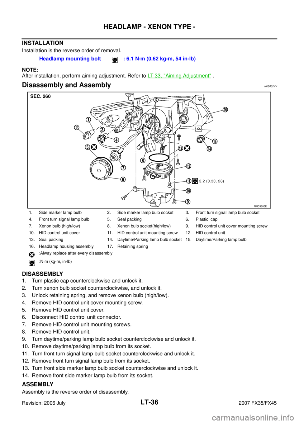
Disassembly and Assembly NKS002VV
DISASSEMBLY
1. Turn plastic cap counterclockwise and unlock it.
2. Turn xenon bulb socket counterclockwise, and unlock it.
3. Unlock retaining spring, and remove xenon bulb (high/low).
4. Remove HID control unit cover mounting screw.
5. Remove HID control unit cover.
6. Disconnect HID control unit connector.
7. Remove HID control unit mounting screws.
8. Remove HID control unit.
9. Turn daytime/parking lamp bulb socket counterclockwise and unlock it.
10. Remove daytime/parking lamp bulb from its socket.
11. Turn front turn signal lamp bulb socket counterclockwise and unlock it.
12. Remove front turn signal lamp bulb from its socket.
13. Turn front side marker lamp bulb socket counterclockwise and unlock it.
14. Remove front side marker lamp bulb from its socket.
ASSEMBLY
Assembly is the reverse order of disassembly. Headlamp mounting bolt : 6.1 N·m (0.62 kg-m, 54 in-lb)
1. Side marker lamp bulb 2. Side marker lamp bulb socket 3. Front turn signal lamp bulb socket
4. Front turn signal lamp bulb 5. Seal packing 6. Plastic cap
7. Xenon bulb (high/low) 8. Xenon bulb socket(high/low) 9. HID control unit cover mounting screw
10. HID control unit cover 11. HID control unit mounting screw 12. HID control unit
13. Seal packing 14. Daytime/Parking lamp bulb socket 15. Daytime/Parking lamp bulb
16. Headlamp housing assembly 17. Retaining spring :Alway replace after every disassembly
:N·m (kg-m, in-lb)
PKIC9685E
Page 3560 of 4366
LT-104
TURN SIGNAL AND HAZARD WARNING LAMPS
Revision: 2006 July 2007 FX35/FX45
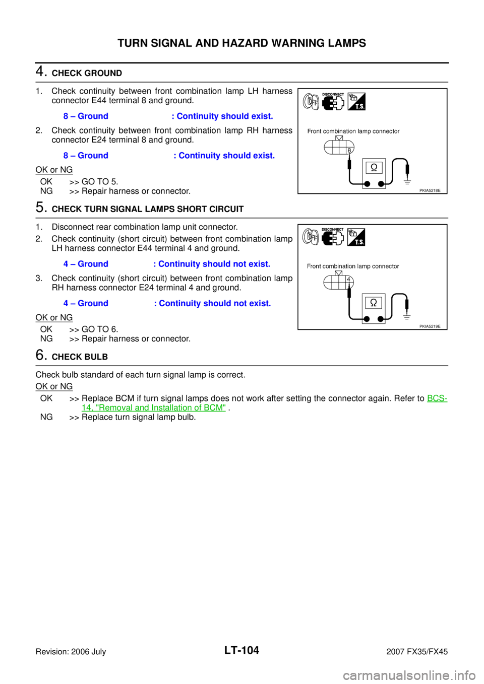
4. CHECK GROUND
1. Check continuity between front combination lamp LH harness connector E44 terminal 8 and ground.
2. Check continuity between front combination lamp RH harness connector E24 terminal 8 and ground.
OK or NG
OK >> GO TO 5.
NG >> Repair harness or connector.
5. CHECK TURN SIGNAL LAMPS SHORT CIRCUIT
1. Disconnect rear combination lamp unit connector.
2. Check continuity (short circuit) between front combination lamp LH harness connector E44 terminal 4 and ground.
3. Check continuity (short circuit) between front combination lamp RH harness connector E24 terminal 4 and ground.
OK or NG
OK >> GO TO 6.
NG >> Repair harness or connector.
6. CHECK BULB
Check bulb standard of each turn signal lamp is correct.
OK or NG
OK >> Replace BCM if turn signal lamps does not work after setting the connector again. Refer to BCS-
14, "Removal and Installation of BCM" .
NG >> Replace turn signal lamp bulb. 8 – Ground : Continuity should exist.
8 – Ground : Continuity should exist.
PKIA5218E
4 – Ground : Continuity should not exist.
4 – Ground : Continuity should not exist.
PKIA5219E
Page 3564 of 4366
LT-108
TURN SIGNAL AND HAZARD WARNING LAMPS
Revision: 2006 July 2007 FX35/FX45
Bulb Replacement (Front Turn Signal Lamp)NKS002XQ
Refer to LT- 3 4 , "Bulb Replacement" .
Bulb Replacement (Rear Turn Signal Lamp)NKS002XR
Refer to LT- 1 5 1 , "Bulb Replacement" .
Removal and Installation of Front Turn Signal LampNKS002XS
Refer to LT- 3 5 , "Removal and Installation" .
Removal and Installation of Rear Turn Signal Lamp NKS002XT
Refer to LT- 1 5 1 , "Removal and Installation" .
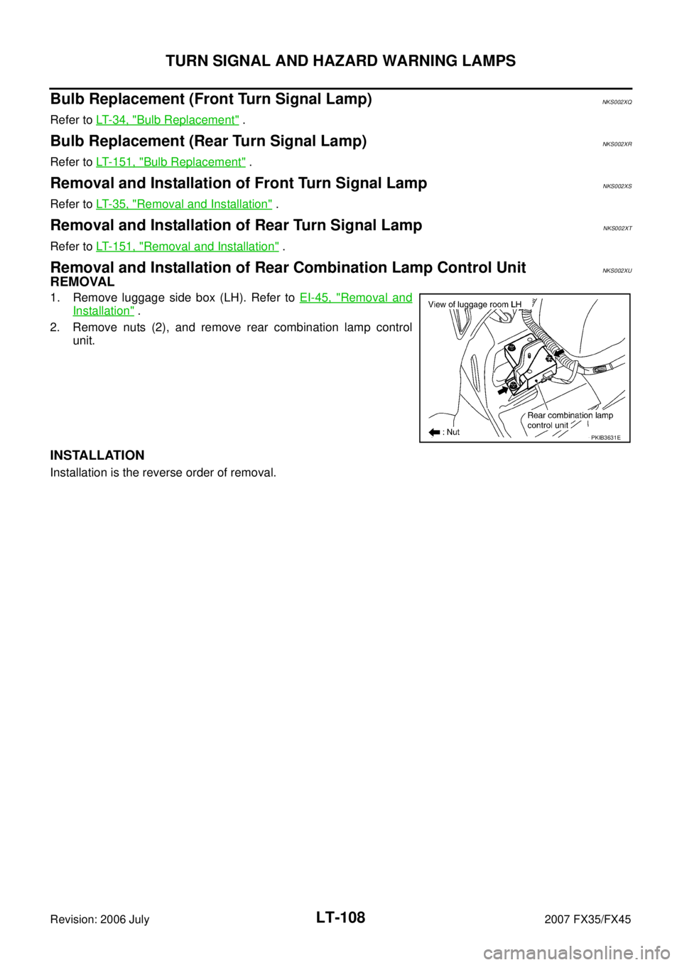
Removal and Installation of Rear Combination Lamp Control UnitNKS002XU
REMOVAL
1. Remove luggage side box (LH). Refer to EI-45, "Removal and
Installation" .
2. Remove nuts (2), and remove rear combination lamp control unit.
INSTALLATION
Installation is the reverse order of removal.
PKIB3631E