Page 3361 of 4366

INSTRUMENT PANEL ASSEMBLY IP-15
C
D E
F
G H
J
K L
M A
B
IP
Revision: 2006 July 2007 FX35/FX45
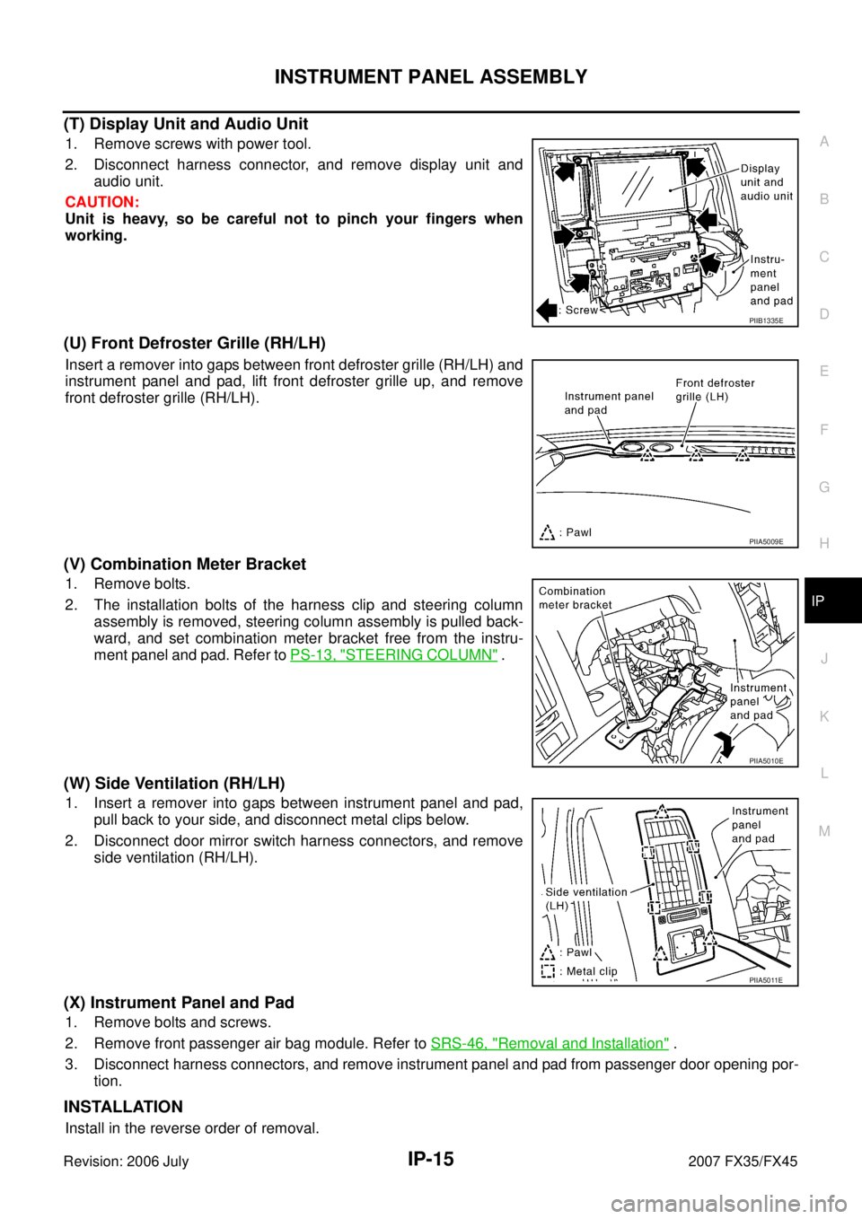
(T) Display Unit and Audio Unit
1. Remove screws with power tool.
2. Disconnect harness connector, and remove display unit and audio unit.
CAUTION:
Unit is heavy, so be careful not to pinch your fingers when
working.
(U) Front Defroster Grille (RH/LH)
Insert a remover into gaps between front defroster grille (RH/LH) and
instrument panel and pad, lift front defroster grille up, and remove
front defroster grille (RH/LH).
(V) Combination Meter Bracket
1. Remove bolts.
2. The installation bolts of the harness clip and steering column assembly is removed, steering column assembly is pulled back-
ward, and set combination meter bracket free from the instru-
ment panel and pad. Refer to PS-13, "
STEERING COLUMN" .
(W) Side Ventilation (RH/LH)
1. Insert a remover into gaps between instrument panel and pad,
pull back to your side, and disconnect metal clips below.
2. Disconnect door mirror switch harness connectors, and remove side ventilation (RH/LH).
(X) Instrument Panel and Pad
1. Remove bolts and screws.
2. Remove front passenger air bag module. Refer to SRS-46, "
Removal and Installation" .
3. Disconnect harness connectors, and remove instrument panel and pad from passenger door opening por- tion.
INSTALLATION
Install in the reverse order of removal.
PIIB1335E
PIIA5009E
PIIA5010E
PIIA5011E
Page 3362 of 4366
IP-16
INSTRUMENT PANEL ASSEMBLY
Revision: 2006 July 2007 FX35/FX45
Disassembly and AssemblyNIS001UG
A/T CONSOLE FINISHER
Disassembly
1. Remove screws with power tool and remove instrument ashtray.
2. Remove screws with power tool and remove instrument clock panel.
3. Remove screws with power tool of back side and remove cup holder.
4. Remove screws of back side and remove position indicator plate.
Assembly
Assemble in the reverse order of disassembly.
1. Instrument clock panel 2. Instrument clock finisher 3. Ashtry
4. Cup holder 5. Cup holder inner 6. A/T console finisher
7. A/T console panel
PIIB8537E
Page 3363 of 4366
INSTRUMENT PANEL ASSEMBLY IP-17
C
D E
F
G H
J
K L
M A
B
IP
Revision: 2006 July 2007 FX35/FX45
CENTER CONSOLE
Disassembly
1. Insert a remover into side between gaps console rear finisher and pull back to your side, and disconnect pawls below.
2. Disconnect harness connector and remove console rear finisher.
3. Insert a remover into side between gaps of console mask and pull back to your side.
4. Remove screws with power tool and remove console lid.
5. Remove screws fixing DVD player with power tool.
6. Disconnect harness connectors, and remove DVD player.
Assembly
Assemble in the reverse order of disassembly.
1. Console lid 2. Console mask 3. Console body
4. DVD player bracket 5. DVD player 6. Console rear finisher
Clip Pawl
PIIB8538E
Page 3364 of 4366
IP-18
INSTRUMENT PANEL ASSEMBLY
Revision: 2006 July 2007 FX35/FX45
INSTRUMENT PASSENGER LOWER PANEL
Disassembly
1. Detach the damper from glove box assembly right side.
2. Remove glove box pins and remove glove box assembly.
3. Remove screws with power tool and remove glove box striker.
Assembly
Assemble in the reverse order of disassembly.
1. Instrument passenger lower panel 2. Glove box 3. Glove box pin
4. Glove box striker 5. Screw
PIIA5012E
PIIA4999E
PIIA5000E
Page 3565 of 4366
LIGHTING AND TURN SIGNAL SWITCH LT-109
C
D E
F
G H
I
J
L
M A
B
LT
Revision: 2006 July 2007 FX35/FX45
LIGHTING AND TURN SIGNAL SWITCHPFP:25540
Removal and InstallationNKS002XV
REMOVAL
1. Remove steering column cover. Refer to IP-10, "INSTRUMENT
PANEL ASSEMBLY" .
2. While pressing pawls in direction as shown in the figure, pull lighting and turn signal switch toward driver door and disconnect
from the base.
INSTALLATION
Installation is the reverse order of removal.
PKIB3477E
Page 3566 of 4366
LT-110
HAZARD SWITCH
Revision: 2006 July 2007 FX35/FX45
HAZARD SWITCHPFP:25290
Removal and InstallationNKS002XW
REMOVAL
1. Remove A/T console finisher. Refer to IP-10, "INSTRUMENT
PANEL ASSEMBLY" .
2. Disconnect the hazard switch connector.
3. Remove the drink holder.
4. Press pawl on reverse side and remove hazard switch.
INSTALLATION
Installation is the reverse order of removal.
PKIC9691E
Page 3638 of 4366

LT-182
INTERIOR ROOM LAMP
Revision: 2006 July 2007 FX35/FX45
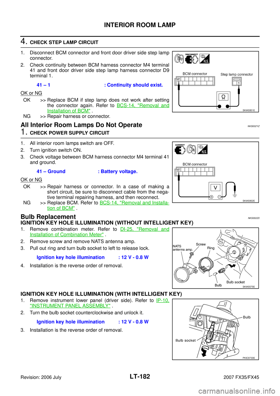
4. CHECK STEP LAMP CIRCUIT
1. Disconnect BCM connector and front door driver side step lamp connector.
2. Check continuity between BCM harness connector M4 terminal 41 and front door driver side step lamp harness connector D9
terminal 1.
OK or NG
OK >> Replace BCM if step lamp does not work after setting the connector again. Refer to BCS-14, "
Removal and
Installation of BCM" .
NG >> Repair harness or connector.
All Interior Room Lamps Do Not OperateNKS002YZ
1. CHECK POWER SUPPLY CIRCUIT
1. All interior room lamps switch are OFF.
2. Turn ignition switch ON.
3. Check voltage between BCM harness connector M4 terminal 41 and ground.
OK or NG
OK >> Repair harness or connector. In a case of making a short circuit, be sure to disconnect cable from the nega-
tive terminal repairing harness, and then reconnect.
NG >> Replace BCM. Refer to BCS-14, "
Removal and Installa-
tion of BCM" .
Bulb ReplacementNKS002Z0
IGNITION KEY HOLE ILLUMINATION (WITHOUT INTELLIGENT KEY)
1. Remove combination meter. Refer to DI-25, "Removal and
Installation of Combination Meter" .
2. Remove screw and remove NATS antenna amp.
3. Pull out ring and turn bulb socket to left to release lock.
4. Installation is the reverse order of removal.
IGNITION KEY HOLE ILLUMINATION (WITH INTELLIGENT KEY)
1. Remove instrument lower panel (driver side). Refer to IP-10,
"INSTRUMENT PANEL ASSEMBLY" .
2. Turn the bulb socket counterclockwise and unlock it.
3. Installation is the reverse order of removal. 41 – 1 : Continuity should exist.
SKIA5951E
41 – Ground : Battery voltage.
SKIA5952E
Ignition key hole illumination : 12 V - 0.8 W
SKIA5575E
Ignition key hole illumination : 12 V - 0.8 W
PKIC9733E
Page 3656 of 4366

LT-200
ILLUMINATION
Revision: 2006 July 2007 FX35/FX45
Bulb ReplacementNKS003N7
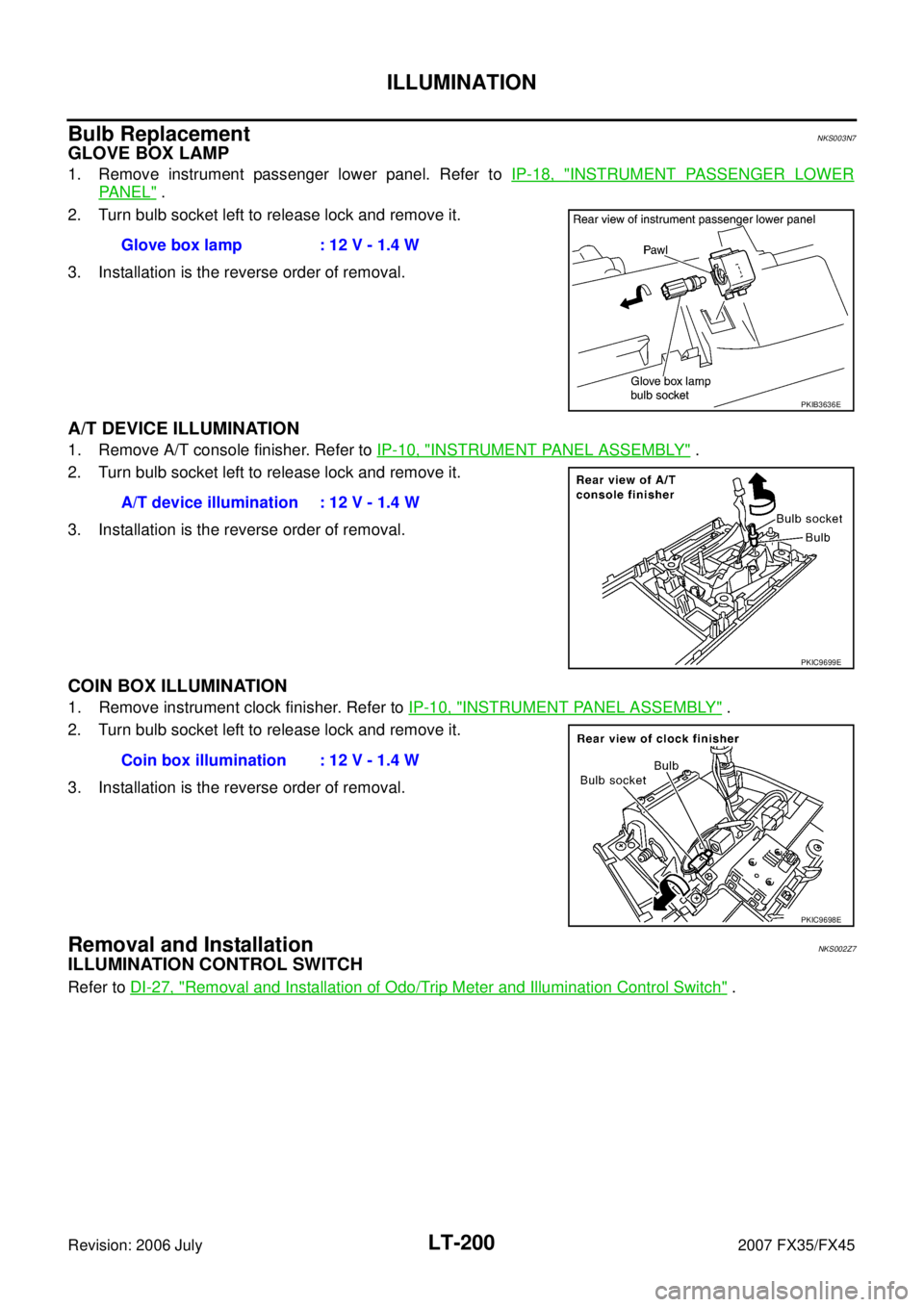
GLOVE BOX LAMP
1. Remove instrument passenger lower panel. Refer to IP-18, "INSTRUMENT PASSENGER LOWER
PA N E L" .
2. Turn bulb socket left to release lock and remove it.
3. Installation is the reverse order of removal.
A/T DEVICE ILLUMINATION
1. Remove A/T console finisher. Refer to IP-10, "INSTRUMENT PANEL ASSEMBLY" .
2. Turn bulb socket left to release lock and remove it.
3. Installation is the reverse order of removal.
COIN BOX ILLUMINATION
1. Remove instrument clock finisher. Refer to IP-10, "INSTRUMENT PANEL ASSEMBLY" .
2. Turn bulb socket left to release lock and remove it.
3. Installation is the reverse order of removal.
Removal and InstallationNKS002Z7
ILLUMINATION CONTROL SWITCH
Refer to DI-27, "Removal and Installation of Odo/Trip Meter and Illumination Control Switch" .
Glove box lamp : 12 V - 1.4 W
PKIB3636E
A/T device illumination : 12 V - 1.4 W
PKIC9699E
Coin box illumination : 12 V - 1.4 W
PKIC9698E