Page 4315 of 4366
FRONT WIPER AND WASHER SYSTEM WW-9
C
D E
F
G H
I
J
L
M A
B
WW
Revision: 2006 July 2007 FX35/FX45
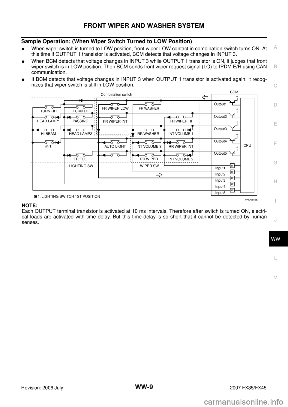
Sample Operation: (When Wiper Switch Turned to LOW Position)
�When wiper switch is turned to LOW position, front wiper LOW contact in combination switch turns ON. At
this time if OUTPUT 1 transistor is activated, BCM detects that voltage changes in INPUT 3.
�When BCM detects that voltage changes in INPUT 3 while OUTPUT 1 transistor is ON, it judges that front
wiper switch is in LOW position. Then BCM sends front wiper request signal (LO) to IPDM E/R using CAN
communication.
�If BCM detects that voltage changes in INPUT 3 when OUTPUT 1 transistor is activated again, it recog-
nizes that wiper switch is still in LOW position.
NOTE:
Each OUTPUT terminal transistor is activated at 10 ms intervals. Therefore after switch is turned ON, electri-
cal loads are activated with time delay. But this time delay is so short that it cannot be detected by human
senses.
PKID0855E
Page 4316 of 4366

WW-10
FRONT WIPER AND WASHER SYSTEM
Revision: 2006 July 2007 FX35/FX45
Operation Mode
Combination switch reading function has operation modes shown below.
1. Normal status
–When BCM is not in sleep status, OUTPUT terminals (1-5) each turn ON-OFF every 10 ms.
2. Sleep status
–When BCM is in sleep status, transistors of OUTPUT 1 and 5 stop the output, and BCM enters low power
mode. Mean while OUTPUT 2, 3, and 4 send out ON signal every 60 ms, and accept input from lighting
switch system.
CAN Communication System DescriptionNKS00328
CAN (Controller Area Network) is a serial communication line for real time application. It is an on-board multi-
plex communication line with high data communication speed and excellent error detection ability. Many elec-
tronic control units are equipped onto a vehicle, and each control unit shares information and links with other
control units during operation (not independent). In CAN communication, control units are connected with 2
communication lines (CAN H line, CAN L line) allowing a high rate of information transmission with less wiring.
Each control unit transmits/receives data but selectively reads required data only.
CAN Communication UnitNKS00329
Refer to LAN-49, "CAN System Specification Chart" .
PKIC4919E
Page 4321 of 4366

FRONT WIPER AND WASHER SYSTEM WW-15
C
D E
F
G H
I
J
L
M A
B
WW
Revision: 2006 July 2007 FX35/FX45
Terminals and Reference Values for BCMNKS0032C
CAUTION:
�Check combination switch system terminal waveform under the loaded condition with lighting
switch, turn signal switch and wiper switch OFF not to be fluctuated by overloaded.
�Turn wiper intermittent dial position to 4 except when checking waveform or voltage of wiper inter-
mittent dial position. Wiper intermittent dial position can be confirmed on CONSULT-II. Refer to LT-
11 7, "DATA MONITOR" .
Te r m i -
nal No. Wire
color Signal name Measuring condition
Reference value
Ignition
switch Operation or condition
4PU/W Combination
switch input 3 ON Lighting,
turn, wiper
switch
(Wiper inter-
mittent dial
position 4) OFF Approx. 0 V
Any of the conditions below
�Front wiper switch MIST
�Front wiper switch INT
�Front wiper switch LO Approx. 1.0 V
5Y/R Combination
switch input 2 ON Lighting,
turn, wiper
switch OFF
(Wiper intermittent dial position 4) Approx. 0 V
Any of the conditions below
�Front washer switch
(Wiper intermittent dial position 4)
�Wiper intermittent dial position 1
�Wiper intermittent dial position 5
�Wiper intermittent dial position 6
Approx. 1.0 V
PKIB4959J
PKIB4959J
Page 4322 of 4366
 Approx. 0 V
An")
WW-16
FRONT WIPER AND WASHER SYSTEM
Revision: 2006 July 2007 FX35/FX45
6SB Combination
switch input 1 ON Lighting,
turn, wiper
switch OFF
(Wiper intermittent dial position 4) Approx. 0 V
Any of the conditions below
�Front wiper switch HI
(Wiper intermittent dial position 4)
�Wiper intermittent dial position 3
Approx. 1.0 V
Any of the conditions below
�Wiper intermittent dial position 1
�Wiper intermittent dial position 2 Approx. 1.7 V
Any of the conditions below
�Wiper intermittent dial position 6
�Wiper intermittent dial position 7 Approx. 0.8 V
32 GY/R Combination
switch output 5 ON Lighting,
turn, wiper
switch OFF
(Wiper intermittent dial position 4)
Approx. 7.2 V
Any of the conditions below
�Wiper intermittent dial position 1
�Wiper intermittent dial position 2
�Wiper intermittent dial position 6
�Wiper intermittent dial position 7 Approx. 1.0 V
Te r m i -
nal No. Wire
color Signal name Measuring condition
Reference value
Ignition
switch Operation or condition
PKIB4959J
PKIB4952J
PKIB4955J
PKIB4960J
PKIB4956J
Page 4323 of 4366

FRONT WIPER AND WASHER SYSTEM WW-17
C
D E
F
G H
I
J
L
M A
B
WW
Revision: 2006 July 2007 FX35/FX45
33 G Combination
switch output 4 ON Lighting,
turn, wiper
switch OFF
(Wiper intermittent dial position 4)
Approx. 7.2 V
Any of the conditions below
�Wiper intermittent dial position 1
�Wiper intermittent dial position 5
�Wiper intermittent dial position 6 Approx. 1.2 V
34 W/B Combination
switch output 3 ON Lighting,
turn, wiper
switch OFF
(Wiper intermittent dial position 4)
Approx. 7.2 V
Any of the conditions below
�Wiper intermittent dial position 1
�Wiper intermittent dial position 2
�Wiper intermittent dial position 3 Approx. 1.2 V
35 W/G Combination
switch output 2 ON Lighting,
turn, wiper
switch
(Wiper inter-
mittent dial
position 4) OFF
Approx. 7.2 V
Any of the conditions below
�Front wiper switch INT
�Front wiper switch HI Approx. 1.2 V
Te r m i -
nal No. Wire
color Signal name Measuring condition
Reference value
Ignition
switch Operation or condition
PKIB4960J
PKIB4958J
PKIB4960J
PKIB4958J
PKIB4960J
PKIB4958J
Page 4324 of 4366

WW-18
FRONT WIPER AND WASHER SYSTEM
Revision: 2006 July 2007 FX35/FX45
Terminals and Reference Values for IPDM E/RNKS0032D
36 W/R Combination
switch output 1 ON Lighting,
turn, wiper
switch
(Wiper inter-
mittent dial
position 4) OFF
Approx. 7.2 V
Any of the conditions below
�Front wiper switch MIST
�Front wiper switch LO
�Front washer switch Approx. 1.2 V
38 W/L Ignition switch
(ON) ON — Battery voltage
39 L CAN − H— — —
40 P CAN − L— — —
42 L/R Battery power
supply OFF — Battery voltage
49 B Ground ON — Approx. 0 V
52 B Ground ON — Approx. 0 V
55 G Battery power
supply OFF — Battery voltage
Te r m i -
nal No. Wire
color Signal name Measuring condition
Reference value
Ignition
switch Operation or condition
PKIB4960J
PKIB4958J
Terminal
No. Wire
color Signal name Measuring condition
Reference value
Ignition
switch Operation or condition
21 P Low speed signal ON Wiper switch OFF Approx. 0 V
LOW Battery voltage
31 PU High speed signal ON Wiper switch OFF Approx. 0 V
HI Battery voltage
32 L Wiper auto - stop signal ON Wiper operating Battery voltage
Wiper stopped Approx. 0 V
38 B Ground ON — Approx. 0 V
44 OR Front and rear washer
pump power supply ON — Battery voltage
48 L CAN − H—— —
49 R CAN − L—— —
60 B Ground ON — Approx. 0 V
Page 4331 of 4366

FRONT WIPER AND WASHER SYSTEM WW-25
C
D E
F
G H
I
J
L
M A
B
WW
Revision: 2006 July 2007 FX35/FX45
6. CHECK CIRCUIT BETWEEN IPDM E/R AND BCM
Select “BCM” on CONSULT-II, and perform self-diagnosis for
“BCM”.
Displayed self
-diagnosis results
NO DTC>>Replace BCM. Refer to BCS-14, "Removal and Installa-
tion of BCM" .
CAN COMM CIRCUIT>>Check CAN communication line of BCM. Refer to BCS-13, "
CAN Communication Inspection
Using CONSULT-II (Self-Diagnosis)" .
Front Wiper Does Not Return to Stop PositionNKS0032J
1. CHECK FRONT WIPER STOP SIGNAL
With CONSULT-ll
Select “IPDM E/R” on CONSULT-II. With “DATA MONITOR”, make
sure that “WIP AUTO STOP” turns “ACT P” - “STOP P” linked with
wiper operation.
Without CONSULT-ll
GO TO 2.
OK or NG
OK >> Replace IPDM E/R.
NG >> GO TO 2.
2. CHECK IPDM E/R
1. Turn ignition switch OFF.
2. Disconnect front wiper motor connector.
3. Turn ignition switch ON.
4. Check voltage between front wiper harness connector E57 ter- minal 5 and ground.
OK or NG
OK >> GO TO 4.
NG >> GO TO 3.
PKIA7627E
PKIA7614E
5 – Ground : Battery voltage.
PKIA7662E
Page 4335 of 4366

FRONT WIPER AND WASHER SYSTEM WW-29
C
D E
F
G H
I
J
L
M A
B
WW
Revision: 2006 July 2007 FX35/FX45
3. CHECK IPDM E/R
With CONSULT-ll
1. Connect IPDM E/R connector and front wiper motor connector.
2. Select “IPDM E/R” by CONSULT-II, and select “ACTIVE TEST” on “SELECT DIAG MODE” screen.
3. Select “FRONT WIPER” on “SELECT TEST ITEM” screen.
4. Touch “HI” screen.
5. Check voltage between IPDM E/R harness connector E7 termi- nal 31 and ground while front wiper HI is operating.
Without CONSULT-ll
1. Connect IPDM E/R connector and front wiper motor connector.
2. Start up auto active test. Refer to PG-21, "
Auto Active Test" .
3. Check voltage between IPDM E/R harness connector E7 terminal 31 and ground while front wiper HI is operating.
OK or NG
OK >> Replace front wiper motor.
NG >> Replace IPDM E/R.
Only Front Wiper Intermittent Does Not OperateNKS0032M
1. CHECK COMBINATION SWITCH
With CONSULT-ll
1. Select “BCM” on CONSULT-II, and select “WIPER” on “SELECT TEST ITEM” screen.
2. Select “DATA MONITOR” on “SELECT DIAG MODE” screen. Make sure that “FR WIPER INT”, turn ON-OFF according to
wiper switch operation.
Without CONSULT-ll
Refer to LT- 11 8 , "
Combination Switch Inspection" .
OK or NG
OK >> Replace BCM. Refer to BCS-14, "Removal and Installa-
tion of BCM" .
NG >> Check combination switch (wiper switch) Refer to LT-
11 8 , "Combination Switch Inspection" .
Front Wiper Interval Time Is Not Controlled by Vehicle SpeedNKS0032N
1. CHECK FUNCTION OF COMBINATION METER
Confirm that speedometer operates normally.
Does front wiper operate normally?
YES >> GO TO 2.
NO >> Combination meter vehicle speed system malfunction. Refer to DI-19, "
Vehicle Speed Signal
Inspection" .
31 – Ground : Battery voltage.
31 – Ground : Battery voltage.
PKIA5198E
PKIB0110E