Page 3764 of 4366

Revision: 2006 July 2007 FX35/FX45
All Signals, Main Signals, Selection From Menu
NOTE:
�Perform monitoring of IPDM E/R data with the")
PG-20
IPDM E/R (INTELLIGENT POWER DISTRIBUTION MODULE ENGINE ROOM)
Revision: 2006 July 2007 FX35/FX45
All Signals, Main Signals, Selection From Menu
NOTE:
�Perform monitoring of IPDM E/R data with the ignition switch ON. When the ignition switch is at ACC, the display may not be cor -
rect.
�*1: The vehicle without the Intelligent Key system displays only ON without change.
�*2:The cornering lamp item is displayed, but it cannot be monitored.
ACTIVE TEST
Operation Procedure
1. Touch “ACTIVE TEST” on “SELECT DIAG MODE” screen.
2. Touch item to be tested.
3. Touch “START”, and confirm its operation.
4. Touch “OFF” while testing to stop the operation.
Item name CONSULT-II
screen display Display or unit SELECT MONITOR ITEM
Description
ALL
SIG-
NALS MAIN
SIG-
NALS SELECTION
FROM
MENU
Motor fan request MOTOR FAN REQ 1/2/3/4 ×× ×Signal status input from ECM
Compressor request AC COMP REQ ON/OFF ×× ×Signal status input from ECM
Tail & clear request TAIL&CLR REQ ON/OFF ×× ×Signal status input from BCM
H/L LO request HL LO REQ ON/OFF ×× ×Signal status input from BCM
H/L HI request HL HI REQ ON/OFF ×× ×Signal status input from BCM
FR fog request FR FOG REQ ON/OFF ×× ×Signal status input from BCM
FR wiper request FR WIP REQ STOP/LO/HI ×× ×Signal status input from BCM
Wiper auto stop WIP AUTO STOP ACT P/STOP P ×× ×Output status of IPDM E/R
Wiper protection WIP PROT OFF/BLOCK ×× ×Control status of IPDM E/R
Starter request ST RLY REQ
*1ON/OFF ×× Status of input signal
Ignition relay status IGN RLY ON/OFF ×× × Ignition relay status monitored
with IPDM E/R
Rear window defog-
ger request RR DEF REQ ON/OFF
×× ×Signal status input from BCM
Oil pressure switch OIL P SW OPEN/CLOSE ××Signal status input in IPDM E/R
Hood switch HOOD SW ON/OFF ××Input signal status
Theft warning horn
request THFT HRN REQ ON/OFF
××Signal status input from BCM
Horn chirp HORN CHIRP ON/OFF ××Output status of IPDM E/R
Cornering lamp
request CRNRNG LMP
REQ
*2OFF/LEFT/
RIGHT ××
Signal status input from BCM
Test item CONSULT-II screen display Description
Tail lamp operation TAIL LAMP With a certain ON-OFF operation, the tail lamp relay can be operated.
Rear window defogger opera-
tion REAR DEFOGGER
With a certain ON-OFF operation, the rear window defogger relay can
be operated.
Front wiper (HI, LO) opera-
tion FRONT WIPER With a certain operation (OFF, HI ON, LO ON), the front wiper relay
(Lo, Hi) can be operated.
Cooling fan operation MOTOR FAN With a certain operation (1, 2, 3, 4), the cooling fan can be operated.
Lamp (HI, LO, FOG) opera-
tion LAMPSWith a certain operation (OFF, HI ON, LO ON, FOG ON), the lamp
relay (Lo, Hi, Fog) can be operated.
Cornering lamp operation CORNERING LAMP
NOTE—
Horn operation HORN With a certain ON-OFF operation, the horn relay can be operated.
Page 3772 of 4366
PG-28
IPDM E/R (INTELLIGENT POWER DISTRIBUTION MODULE ENGINE ROOM)
Revision: 2006 July 2007 FX35/FX45
Removal and Installation of IPDM E/RNKS003GL
REMOVAL
1. Remove battery. Refer to SC-10, "Removal and Installation" .
2. Remove IPDM E/R cover A. While pressing pawl on backside of IPDM E/R cover B toward vehicle front to unlock, lift up IPDM E/
R.
3. While pressing pawls on right and left side of IPDM E/R, remove IPDM E/R cover B from IPDM E/R.
4. Remove harness connector from IPDM E/R.
INSTALLATION
Installation is the reverse order of removal.
SKIA4968E
SKIA1902E
SKIA4969E
Page 3808 of 4366
 NKS003GO
Use the chart below to find out what each wiring diagram code stands for.
Refer to the wiring diagram code")
PG-64
HARNESS
Revision: 2006 July 2007 FX35/FX45
Wiring Diagram Codes (Cell Codes) NKS003GO
Use the chart below to find out what each wiring diagram code stands for.
Refer to the wiring diagram code in the alphabetical index to find the location (page number) of each wiring
diagram.
Code Section Wiring Diagram Name
A/C ATC Air Conditioner
AF1B1 EC Air Fuel Ratio Sensor 1 Bank 1
AF1B2 EC Air Fuel Ratio Sensor 1 Bank 2
AF1HB1 EC Air Fuel Ratio Sensor 1 Heater Bank 1
AF1HB2 EC Air Fuel Ratio Sensor 1 Heater Bank 2
APPS1 EC Accelerator Pedal Position Sensor
APPS2 EC Accelerator Pedal Position Sensor
APPS3 EC Accelerator Pedal Position Sensor
ASC/BS EC Automatic Speed Control Device (ASCD) Brake Switch
ASC/SW EC Automatic Speed Control Device (ASCD) Steering Switch
ASCBOF EC Automatic Speed Control Device (ASCD) Brake Switch
ASCIND EC Automatic Speed Control Device (ASCD) Indicator
AT/IND DI A/T Indicator Lamp
AUDIO AV Audio
AUT/DP SE Automatic Drive Positioner
AUTO/L LT Automatic Light System
AWD TF AWD Control System
B/CLOS BL Back Door Closure System
BACK/L LT Back-Up Lamp
BRK/SW EC Brake Switch
CAN AT CAN Communication Line
CAN EC CAN Communication Line
CAN LAN CAN System
CHARGE SC Charging System
CHIME DI Warning Chime
CLOCK DI Clock
COMBSW LT Combination Switch
COMM AV Audio Visual Communication Line
COMPAS DI Compass
COOL/F EC Cooling Fan Control
D/LOCK BL Power Door Lock
DEF GW Rear Window Defogger
DTRL LT Headlamp - With Daytime Light System
ECM/PW EC ECM Power Supply for Back-Up
ECTS EC Engine Coolant Temperature Sensor
ETC1 EC Electric Throttle Control Function
ETC2 EC Electric Throttle Control Motor Relay
ETC3 EC Electric Throttle Control Motor
F/FOG LT Front Fog Lamp
F/PUMP EC Fuel Pump
FTS AT A/T Fluid Temperature Sensor Circuit
Page 3810 of 4366

PHSB1 EC Camshaft Position")
PG-66
HARNESS
Revision: 2006 July 2007 FX35/FX45
P/SCKT WW Power Socket
PGC/V EC EVAP Canister Purge Volume Control Solenoid Valve
PHASE EC Camshaft Position Sensor (PHASE)
PHSB1 EC Camshaft Position Sensor (PHASE) (Bank 1)
PHSB2 EC Camshaft Position Sensor (PHASE) (Bank 2)
PNP/SW AT Park/Neutral Position Switch
PNP/SW EC Park/Neutral Position Switch
POS EC Crankshaft Position Sensor (CKPS) (POS)
POWER PG Power Supply Routing
PRE/SE EC EVAP Control System Pressure Sensor
PS/SEN EC Power Steering Pressure Sensor
R/VIEW DI Rear View Camera Control System
ROOM/L LT Interior Room Lamp
RP/SEN EC Refrigerant Pressure Sensor
SEAT SE Power Seat
SEN/PW EC Sensor Power Supply
SHIFT AT A/T Shift Lock System
SNOWSW EC Snow Mode Switch
SROOF RF Sunroof
SRS SRS Supplemental Restraint System
START SC Starting System
STOP/L LT Stop Lamp
STSIG AT Start Signal Circuit
T/WARN WT Low Tire Pressure Warning System
TAIL/L LT Parking, License and Tail Lamps
TPS1 EC Throttle Position Sensor (Sensor 1)
TPS2 EC Throttle Position Sensor (Sensor 2)
TPS3 EC Throttle Position Sensor
TRNSCV BL Homelink Universal Transceiver
TURN LT Turn Signal and Hazard Warning Lamp
VDC BRC Vehicle Dynamics Control System
VEHSEC BL Vehicle Security System
VENT/V EC EVAP Canister Vent Control Valve
VIAS EC Variable Induction Air Control System
VIAS/V EC VIAS Control Solenoid Valve
VSSA/T AT Vehicle Speed Sensor A/T (Revolution Sensor)
WARN DI Warning Lamps
WINDOW GW Power Window
WIP/R WW Rear Wiper and Washer
WIPER WW Front Wiper and Washer Code Section Wiring Diagram Name
Page 3815 of 4366
HARNESS CONNECTOR PG-71
C
D E
F
G H
I
J
L
M A
B
PG
Revision: 2006 July 2007 FX35/FX45
HARNESS CONNECTOR PFP:00011
DescriptionNKS003GQ
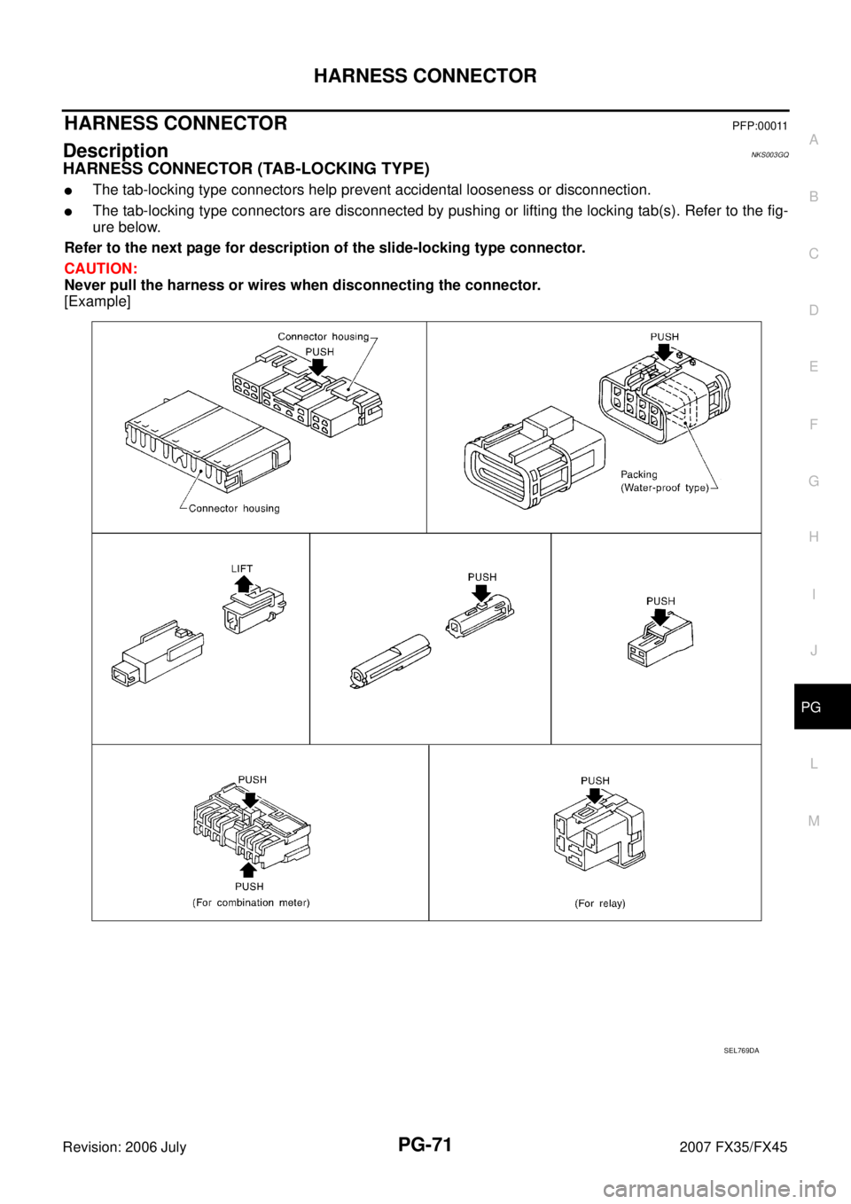
HARNESS CONNECTOR (TAB-LOCKING TYPE)
�The tab-locking type connectors help prevent accidental looseness or disconnection.
�The tab-locking type connectors are disconnected by pushing or lifting the locking tab(s). Refer to the fig-
ure below.
Refer to the next page for description of the slide-locking type connector.
CAUTION:
Never pull the harness or wires when disconnecting the connector.
[Example]
SEL769DA
Page 3816 of 4366
PG-72
HARNESS CONNECTOR
Revision: 2006 July 2007 FX35/FX45
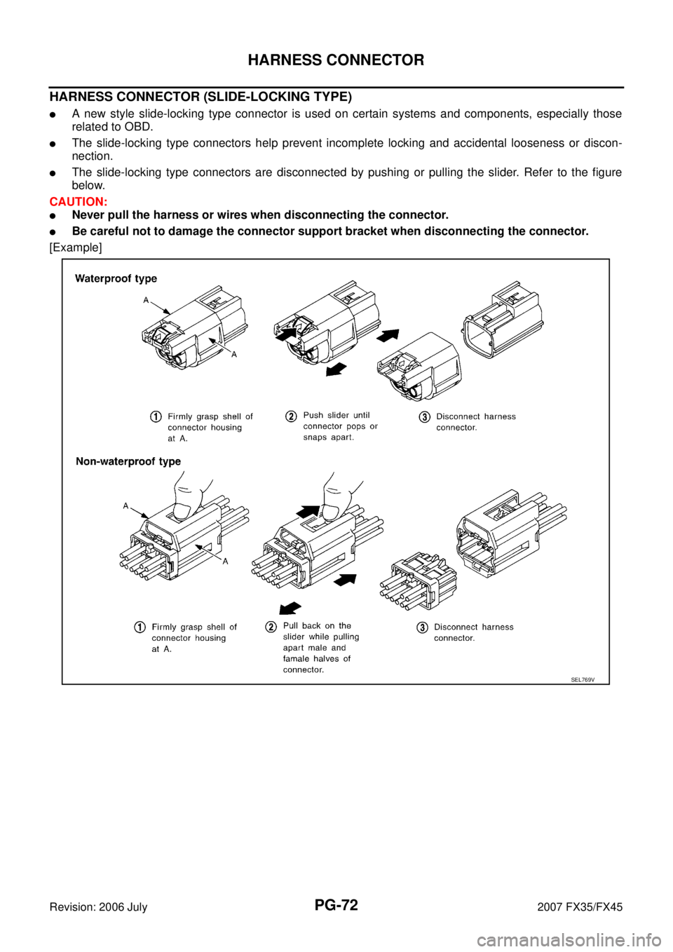
HARNESS CONNECTOR (SLIDE-LOCKING TYPE)
�A new style slide-locking type connector is used on certain systems and components, especially those
related to OBD.
�The slide-locking type connectors help prevent incomplete locking and accidental looseness or discon-
nection.
�The slide-locking type connectors are disconnected by pushing or pulling the slider. Refer to the figure
below.
CAUTION:
�Never pull the harness or wires when disconnecting the connector.
�Be careful not to damage the connector support bracket when disconnecting the connector.
[Example]
SEL769V
Page 3817 of 4366
HARNESS CONNECTOR PG-73
C
D E
F
G H
I
J
L
M A
B
PG
Revision: 2006 July 2007 FX35/FX45
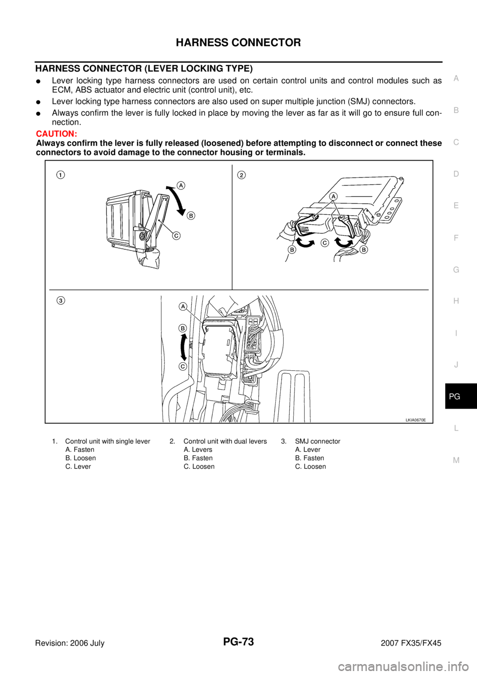
HARNESS CONNECTOR (LEVER LOCKING TYPE)
�Lever locking type harness connectors are used on certain control units and control modules such as
ECM, ABS actuator and electric unit (control unit), etc.
�Lever locking type harness connectors are also used on super multiple junction (SMJ) connectors.
�Always confirm the lever is fully locked in place by moving the lever as far as it will go to ensure full con-
nection.
CAUTION:
Always confirm the lever is fully released (loosened) before attempting to disconnect or connect these
connectors to avoid damage to the connector housing or terminals.
LKIA0670E
1. Control unit with single lever
A. Fasten
B. Loosen
C. Lever 2. Control unit with dual levers
A. Levers
B. Fasten
C. Loosen 3. SMJ connector
A. Lever
B. Fasten
C. Loosen
Page 3824 of 4366
PG-80
FUSE BLOCK - JUNCTION BOX (J/B)
Revision: 2006 July 2007 FX35/FX45
FUSE BLOCK - JUNCTION BOX (J/B)PFP:24350
Terminal ArrangementNKS003GU
CKIM0652E

Revision: 2006 July 2007 FX35/FX45
Removal and Installation of IPDM E/RNKS003GL
REMOVAL
1. Remove battery. Refer to SC-10, \"Removal a")

Revision: 2006 July 2007 FX35/FX45
FUSE BLOCK - JUNCTION BOX (J/B)PFP:24350
Terminal ArrangementNKS003GU
CKIM0652E")