Page 2866 of 4366
EM-74
[VQ35DE]
TIMING CHAIN
Revision: 2006 July 2007 FX35/FX45
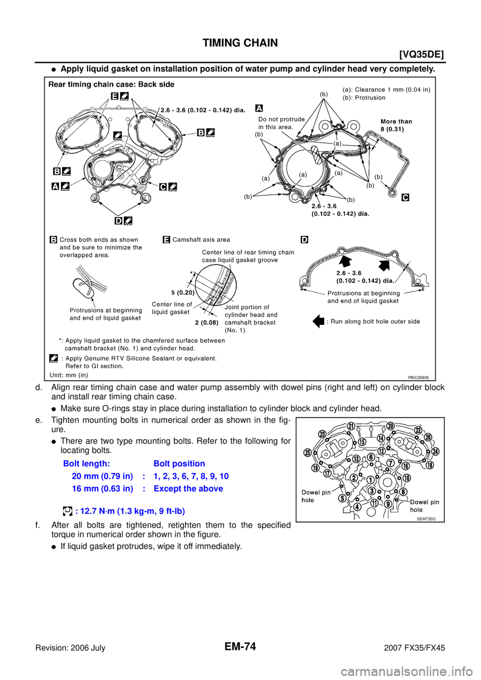
�Apply liquid gasket on installation position of water pump and cylinder head very completely.
d. Align rear timing chain case and water pump assembly with dowel pins (right and left) on cylinder block and install rear timing chain case.
�Make sure O-rings stay in place during installation to cylinder block and cylinder head.
e. Tighten mounting bolts in numerical order as shown in the fig- ure.
�There are two type mounting bolts. Refer to the following for
locating bolts.
f. After all bolts are tightened, retighten them to the specified torque in numerical order shown in the figure.
�If liquid gasket protrudes, wipe it off immediately. Bolt length: Bolt position
20 mm (0.79 in) : 1, 2, 3, 6, 7, 8, 9, 10
16 mm (0.63 in) : Except the above
: 12.7 N·m (1.3 kg-m, 9 ft-lb)
PBIC2680E
SEM735G
Page 2867 of 4366
![INFINITI FX35 2007 Service Manual TIMING CHAIN EM-75
[VQ35DE]
C
D E
F
G H
I
J
K L
M A
EM
Revision: 2006 July 2007 FX35/FX45
g. After installing rear timing chain case, check the surface height
difference between the foll](/manual-img/42/57018/w960_57018-2866.png "INFINITI FX35 2007 Service Manual TIMING CHAIN EM-75
[VQ35DE]
C
D E
F
G H
I
J
K L
M A
EM
Revision: 2006 July 2007 FX35/FX45
g. After installing rear timing chain case, check the surface height
difference between the foll")
TIMING CHAIN EM-75
[VQ35DE]
C
D E
F
G H
I
J
K L
M A
EM
Revision: 2006 July 2007 FX35/FX45
g. After installing rear timing chain case, check the surface height
difference between the following parts on the oil pan (upper)
mounting surface.
�If not within the standard, repeat the installation procedure.
3. Install water pump with new O-rings. Refer to CO-22, "
WATER PUMP" .
4. Make sure that dowel pin hole, dowel pin and crankshaft key are located as shown in the figure. (No. 1 cylinder at compression
TDC)
NOTE:
Though camshaft does not stop at the position as shown in the
figure, for the placement of cam nose, it is generally accepted
camshaft is placed for the same direction of the figure.
CAUTION:
Hole on small dia. side must be used for intake side dowel pin hole. Do not misidentify (ignore big
dia. side).
5. Install timing chains (secondary) and camshaft sprockets as follows:
CAUTION:
Mating marks between timing chain and sprockets slip easily. Confirm all mating mark positions
repeatedly during the installation process.
a. Push plunger of timing chain tensioner (secondary) and keep it pressed in with a stopper pin. Standard
Rear timing chain case to cylinder block: –0.24 to 0.14 mm (–0.009 to 0.006 in)
SEM943G
Camshaft dowel pin hole (intake side): At cylinder head upper face side in each bank.
Camshaft dowel pin (exhaust side) : At cylinder head upper face side in each bank.
Crankshaft key : At cylinder head side of right bank.
KBIA1073E
SEM430G
Page 2874 of 4366
![INFINITI FX35 2007 Service Manual EM-82
[VQ35DE]
TIMING CHAIN
Revision: 2006 July 2007 FX35/FX45
c. Tighten crankshaft pulley bolt.
d. Put a paint mark on crankshaft pulley aligning with angle mark on crankshaft pulley bolt.
e. Fur](/manual-img/42/57018/w960_57018-2873.png "INFINITI FX35 2007 Service Manual EM-82
[VQ35DE]
TIMING CHAIN
Revision: 2006 July 2007 FX35/FX45
c. Tighten crankshaft pulley bolt.
d. Put a paint mark on crankshaft pulley aligning with angle mark on crankshaft pulley bolt.
e. Fur")
EM-82
[VQ35DE]
TIMING CHAIN
Revision: 2006 July 2007 FX35/FX45
c. Tighten crankshaft pulley bolt.
d. Put a paint mark on crankshaft pulley aligning with angle mark on crankshaft pulley bolt.
e. Further tighten by 90 degrees. (Angle tightening)
�Check the tightening angle by referencing to the notches. The
angle between two notches is 90 degrees.
19. Rotate crankshaft pulley in normal direction (clockwise when viewed from front) to confirm it turns smoothly.
20. For the following operations, perform steps in the reverse order of removal.
INSPECTION AFTER INSTALLATION
Inspection for Leaks
The following are procedures for checking fluids leak, lubricates leak.
�Before starting engine, check oil/fluid levels including engine coolant and engine oil. If less than required
quantity, fill to the specified level. Refer to GI-48, "
RECOMMENDED CHEMICAL PRODUCTS AND
SEALANTS" .
�Use procedure below to check for fuel leakage.
–Turn ignition switch “ON” (with engine stopped). With fuel pressure applied to fuel piping, check for fuel
leakage at connection points.
–Start engine. With engine speed increased, check again for fuel leakage at connection points.
�Run engine to check for unusual noise and vibration.
NOTE:
If hydraulic pressure inside chain tensioner drops after removal/installation, slack in guide may generate a
pounding noise during and just after the engine start. However, this does not indicate an unusualness.
Noise will stop after hydraulic pressure rises.
�Warm up engine thoroughly to make sure there is no leakage of fuel, or any oil/fluids including engine oil
and engine coolant.
�Bleed air from lines and hoses of applicable lines, such as in cooling system.
�After cooling down engine, again check oil/fluid levels including engine oil and engine coolant. Refill to the
specified level, if necessary.
Summary of the inspection items:
* Transmission/transaxle/CVT fluid. power steering fluid, brake fluid, etc.
: 44.1 N·m (4.5 kg-m, 33 ft-lb)
PBIC4821E
Item Before starting engine Engine running After engine stopped
Engine coolant Level Leakage Level
Engine oil Level Leakage Level
Other oils and fluid* Level Leakage Level
Fuel Leakage Leakage Leakage
Page 2877 of 4366
![INFINITI FX35 2007 Service Manual CAMSHAFT EM-85
[VQ35DE]
C
D E
F
G H
I
J
K L
M A
EM
Revision: 2006 July 2007 FX35/FX45
�Equally loosen camshaft bracket bolts in several steps in
reverse order as shown in the figure.
5.](/manual-img/42/57018/w960_57018-2876.png "INFINITI FX35 2007 Service Manual CAMSHAFT EM-85
[VQ35DE]
C
D E
F
G H
I
J
K L
M A
EM
Revision: 2006 July 2007 FX35/FX45
�Equally loosen camshaft bracket bolts in several steps in
reverse order as shown in the figure.
5.")
CAMSHAFT EM-85
[VQ35DE]
C
D E
F
G H
I
J
K L
M A
EM
Revision: 2006 July 2007 FX35/FX45
�Equally loosen camshaft bracket bolts in several steps in
reverse order as shown in the figure.
5. Remove camshaft.
6. Remove valve lifter.
�Identify installation positions, and store them without mixing them up.
7. Remove timing chain tensioner (secondary) from cylinder head.
�Remove timing chain tensioner (secondary) with its stopper
pin attached.
NOTE:
Stopper pin was attached when timing chain (secondary) was
removed.
INSPECTION AFTER REMOVAL
Camshaft Runout
1. Put V-block on precise flat table, and support No. 2 and 4 jour- nals of camshaft.
CAUTION:
Do not support No. 1 journal (on the side of camshaft
sprocket) because it has a different diameter from the other
three locations.
2. Set a dial indicator vertically to No. 3 journal.
3. Turn camshaft to one direction with hands, and measure the camshaft runout on a dial indicator. (Total indicator reading)
4. If it exceeds the limit, replace camshaft.
PBIC2050E
PBIC2111E
Standard : Less than 0.02 mm (0.0008 in)
Limit : 0.05 mm (0.0020 in)PBIC0929E
Page 2879 of 4366
![INFINITI FX35 2007 Service Manual CAMSHAFT EM-87
[VQ35DE]
C
D E
F
G H
I
J
K L
M A
EM
Revision: 2006 July 2007 FX35/FX45
Camshaft End Play
�Install a dial indicator in thrust direction on front end of camshaft.
Measure th](/manual-img/42/57018/w960_57018-2878.png "INFINITI FX35 2007 Service Manual CAMSHAFT EM-87
[VQ35DE]
C
D E
F
G H
I
J
K L
M A
EM
Revision: 2006 July 2007 FX35/FX45
Camshaft End Play
�Install a dial indicator in thrust direction on front end of camshaft.
Measure th")
CAMSHAFT EM-87
[VQ35DE]
C
D E
F
G H
I
J
K L
M A
EM
Revision: 2006 July 2007 FX35/FX45
Camshaft End Play
�Install a dial indicator in thrust direction on front end of camshaft.
Measure the end play of a dial indicator when camshaft is
moved forward/backward (in direction to axis).
�Measure the following parts if out of the limit.
–Dimension “A” for camshaft No. 1 journal
–Dimension “B” for cylinder head No. 1 journal bearing
�Refer to the standards above, and then replace camshaft and/or
cylinder head.
Camshaft Sprocket Runout
1. Put V-block on precise flat table, and support No. 2 and 4 journals of camshaft.
CAUTION:
Do not support No. 1 journal (on the side of camshaft sprocket) because it has a different diameter
from the other three locations.
2. Measure the camshaft sprocket runout with a dial indicator. (Total indicator reading)
�If it exceeds the limit, replace camshaft sprocket.
Valve Lifter
Check if surface of valve lifter has any wear or cracks.
�If anything above is found, replace valve lifter. Refer to EM-154,
"Available Valve Lifter" .
Standard : 0.115 - 0.188 mm (0.0045 - 0.0074 in)
Limit : 0.24 mm (0.0094 in)
SEM864E
Standard : 27.500 - 27.548 mm (1.0827 - 1.0846 in)
Standard : 27.360 - 27.385 mm (1.0772 - 1.0781 in)
KBIA2404J
Limit : 0.15 mm (0.0059 in)
PBIC0930E
KBIA0182E
Page 2885 of 4366
![INFINITI FX35 2007 Service Manual CAMSHAFT EM-93
[VQ35DE]
C
D E
F
G H
I
J
K L
M A
EM
Revision: 2006 July 2007 FX35/FX45
Summary of the inspection items:
* Transmission/transaxle/CVT fluid. power steering fluid, brake flui](/manual-img/42/57018/w960_57018-2884.png "INFINITI FX35 2007 Service Manual CAMSHAFT EM-93
[VQ35DE]
C
D E
F
G H
I
J
K L
M A
EM
Revision: 2006 July 2007 FX35/FX45
Summary of the inspection items:
* Transmission/transaxle/CVT fluid. power steering fluid, brake flui")
CAMSHAFT EM-93
[VQ35DE]
C
D E
F
G H
I
J
K L
M A
EM
Revision: 2006 July 2007 FX35/FX45
Summary of the inspection items:
* Transmission/transaxle/CVT fluid. power steering fluid, brake fluid, etc.
Va l v e C l e a r a n c eNBS003GS
INSPECTION
Perform inspection as follows after removal, installation or replacement of camshaft or valve-related parts, or if
there is unusual engine conditions regarding valve clearance.
In cases of removing/installing or replacing camshaft and valve-
related parts, or of unusual engine conditions due to changes in
valve clearance (found malfunctions during stating, idling or causing
noise), perform inspection as follows:
1. Remove rocker covers (right and left bank). Refer to EM-51, "
ROCKER COVER" .
2. Measure the valve clearance as follows:
a. Set No. 1 cylinder at TDC of its compression stroke.
�Rotate crankshaft pulley clockwise to align timing mark
(grooved line without color) with timing indicator.
�Make sure that intake and exhaust cam nose on No. 1 cylin-
der (engine front side of right bank) are located as shown in
the figure.
�If not, turn crankshaft one revolution (360 degrees) and align
as shown in the figure.
Item Before starting engine Engine running After engine stopped
Engine coolant Level Leakage Level
Engine oil Level Leakage Level
Other oils and fluid* Level Leakage Level
Fuel Leakage Leakage Leakage
SEM713A
KBIA1717J
SEM418G
Page 2886 of 4366
![INFINITI FX35 2007 Service Manual EM-94
[VQ35DE]
CAMSHAFT
Revision: 2006 July 2007 FX35/FX45
b. Use a feeler gauge, measure the clearance between valve lifter
and camshaft.
Valve clearance:
Unit: mm (in)
*: Approximately 80 °C (1](/manual-img/42/57018/w960_57018-2885.png "INFINITI FX35 2007 Service Manual EM-94
[VQ35DE]
CAMSHAFT
Revision: 2006 July 2007 FX35/FX45
b. Use a feeler gauge, measure the clearance between valve lifter
and camshaft.
Valve clearance:
Unit: mm (in)
*: Approximately 80 °C (1")
EM-94
[VQ35DE]
CAMSHAFT
Revision: 2006 July 2007 FX35/FX45
b. Use a feeler gauge, measure the clearance between valve lifter
and camshaft.
Valve clearance:
Unit: mm (in)
*: Approximately 80 °C (176 °F)
�By referring to the figure, measure the valve clearances at
locations marked “ ×” as shown in the table below (locations
indicated in the figure).
�No. 1 cylinder at compression TDC
c. Rotate crankshaft by 240 degrees clockwise (when viewed from engine front) to align No. 3 cylinder at TDC of its compression stroke.
NOTE:
�To align cylinder No.3 with the compression top dead center,
place matching marks (A) on the crankshaft pulley (1) side
and on the cylinder block side at a point 240 °counterclock-
wise from the compression top dead center using the hex
head of the crankshaft pulley bolt as a guide.
SEM139D
Items Cold Hot * (reference data)
Intake 0.26 - 0.34 (0.010 - 0.013) 0.304 - 0.416 (0.012 - 0.016)
Exhaust 0.29 - 0.37 (0.011 - 0.015) 0.308 - 0.432 (0.012 - 0.017)
Measuring position (right bank) No. 1 CYL. No. 3 CYL. No. 5 CYL.
No. 1 cylinder at
compression TDC EXH
×
INT ×
Measuring position (left bank) No. 2 CYL. No. 4 CYL. No. 6 CYL.
No. 1 cylinder at
compression TDC INT
×
EXH ×
PBIC2054E
PBIC4628J
Page 2887 of 4366
CAMSHAFT EM-95
[VQ35DE]
C
D E
F
G H
I
J
K L
M A
EM
Revision: 2006 July 2007 FX35/FX45
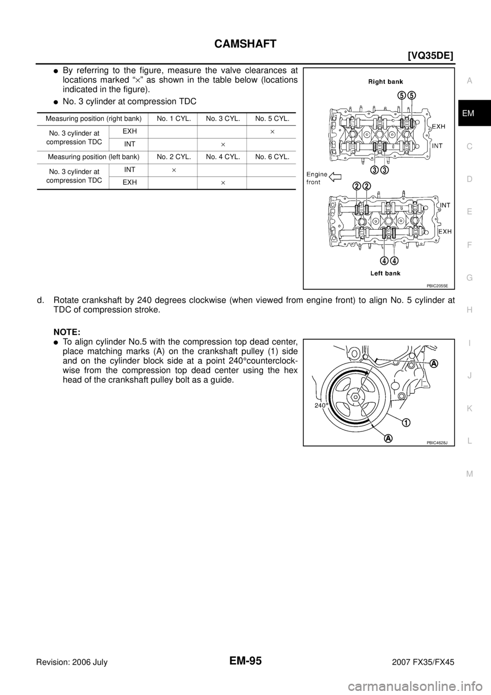
�By referring to the figure, measure the valve clearances at
locations marked “ ×” as shown in the table below (locations
indicated in the figure).
�No. 3 cylinder at compression TDC
d. Rotate crankshaft by 240 degrees clockwise (when viewed from engine front) to align No. 5 cylinder at TDC of compression stroke.
NOTE:
�To align cylinder No.5 with the compression top dead center,
place matching marks (A) on the crankshaft pulley (1) side
and on the cylinder block side at a point 240 °counterclock-
wise from the compression top dead center using the hex
head of the crankshaft pulley bolt as a guide.
Measuring position (right bank) No. 1 CYL. No. 3 CYL. No. 5 CYL.
No. 3 cylinder at
compression TDC EXH
×
INT ×
Measuring position (left bank) No. 2 CYL. No. 4 CYL. No. 6 CYL.
No. 3 cylinder at
compression TDC INT
×
EXH ×
PBIC2055E
PBIC4628J