Page 2959 of 4366
![INFINITI FX35 2007 Service Manual PREPARATION EM-167
[VK45DE]
C
D E
F
G H
I
J
K L
M A
EM
Revision: 2006 July 2007 FX35/FX45
PREPARATIONPFP:00002
Special Service ToolsNBS003HI
The actual shapes of Kent-Moore tools may diff](/manual-img/42/57018/w960_57018-2958.png "INFINITI FX35 2007 Service Manual PREPARATION EM-167
[VK45DE]
C
D E
F
G H
I
J
K L
M A
EM
Revision: 2006 July 2007 FX35/FX45
PREPARATIONPFP:00002
Special Service ToolsNBS003HI
The actual shapes of Kent-Moore tools may diff")
PREPARATION EM-167
[VK45DE]
C
D E
F
G H
I
J
K L
M A
EM
Revision: 2006 July 2007 FX35/FX45
PREPARATIONPFP:00002
Special Service ToolsNBS003HI
The actual shapes of Kent-Moore tools may differ from those of special service tools illustrated here.
Tool number
(Kent-Moore No.)
Tool name Description
KV10111100
(J–37228)
Seal cutter Removing steel oil pan and front cover
KV10114400
(J-38365)
Heated oxygen sensor wrench Loosening or tightening air fuel ratio sensors
and heated oxygen sensors
a: 22 mm (0.87 in)
EG15050500
(J–45402)
Compression gauge adapter Inspection of compression pressure
KV10116200
(J–26336-A)
Valve spring compressor
1. KV10115900
(J–26336-20)
Attachment
2. KV10109220
(—)
Adapter Disassembling valve mechanism
Part (1) is a component of KV10116200
(J26336-A), but part (2) is not so.
KV101151S0
(J–38972)
Lifter stopper set
1. KV10115110
(J–38972-1)
Camshaft pliers
2. KV10115120
(J–38972-2)
Lifter stopper Changing valve lifter shims
KV10112100
(BT8653-A)
Angle wrench Tightening bolts for bearing cap, cylinder
head, etc.
S-NT046
S-NT636
ZZA1225D
PBIC1650E
S-NT041
S-NT014
Page 2961 of 4366
PREPARATION EM-169
[VK45DE]
C
D E
F
G H
I
J
K L
M A
EM
Revision: 2006 July 2007 FX35/FX45
Commercial Service ToolsNBS003HJ
—
(J-45476)
Ring gear stopper Removing and installing crankshaft pulley
—
(J-45488)
Quick connector release Removing fuel tube quick connectors in
engine room
Tool number
(Kent-Moore No.)
Tool name Description
PBIC1655E
PBIC0198E
(Kent-Moore No.)
Tool name Description
(—)
Power tool Loosening nuts and bolts
(—)
Spark plug wrench Removing and installing spark plug
(—)
Manual lift table caddy Removing and installing engine
(J–24239-01)
Cylinder head bolt wrench Loosening and tightening cylinder head bolt,
and use with angle wrench [SST:
KV10112100 (BT–8653-A)]
a: 13 (0.51) dia.
b: 12 (0.47)
c: 10 (0.39)
Unit: mm (in)
PBIC0190E
S-NT047
ZZA1210D
NT583
Page 2972 of 4366
![INFINITI FX35 2007 Service Manual EM-180
[VK45DE]
INTAKE MANIFOLD
Revision: 2006 July 2007 FX35/FX45
�Refer to GI-11, "Components" for symbol marks in the figure.
Removal and InstallationNBS004LY
REMOVAL
WARNING:
To avoid the dange](/manual-img/42/57018/w960_57018-2971.png "INFINITI FX35 2007 Service Manual EM-180
[VK45DE]
INTAKE MANIFOLD
Revision: 2006 July 2007 FX35/FX45
�Refer to GI-11, \"Components\" for symbol marks in the figure.
Removal and InstallationNBS004LY
REMOVAL
WARNING:
To avoid the dange")
EM-180
[VK45DE]
INTAKE MANIFOLD
Revision: 2006 July 2007 FX35/FX45
�Refer to GI-11, "Components" for symbol marks in the figure.
Removal and InstallationNBS004LY
REMOVAL
WARNING:
To avoid the danger of being scalded, never drain the engine coolant when the engine is hot.
1. Remove engine cover with power tool.
2. Release fuel pressure. Refer to EC-747, "
FUEL PRESSURE RELEASE" .
3. Remove air duct (inlet), power duct, air cleaner case and air duct and resonator assembly. Refer to EM-
177, "AIR CLEANER AND AIR DUCT" .
4. Drain engine coolant from radiator. Refer to CO-38, "
DRAINING ENGINE COOLANT" .
CAUTION:
�Perform this step when the engine is cold.
�Do not spill engine coolant on drive belts.
1. PCV tube 2. PCV hose 3. PCV hose
4. Engine cover bracket (RH) 5. EVAP canister purge control sole-
noid valve 6. EVAP hose
7. EVAP service port 8. EVAP tube 9. Vacuum hose
10. Vacuum hose 11. PCV hose 12. PCV tube
13. PCV hose 14. PCV hose 15. Water hose
16. EVAP hose 17. Water hose 18. Intake manifold adapter
19. Gasket 20. Electric throttle control actuator 21. Gasket
22. Gasket 23. Intake manifold (lower) 24. Vacuum hose
25. VIAS control solenoid valve 26. Vacuum hose 27. Vacuum hose
28. Vacuum tank 29. Vacuum hose 30. Engine cover bracket (LH)
31. Vacuum hose 32. Water hose 33. Gasket
34. Intake manifold (upper)
A. To centralized under-floor piping B. To rocker cover (right bank) C. To rocker cover (left bank)
D. To thermostat housing E. To air duct and resonator assembly F. To heater pipe
PBIC4553E
Page 2978 of 4366
![INFINITI FX35 2007 Service Manual EM-186
[VK45DE]
EXHAUST MANIFOLD AND THREE WAY CATALYST
Revision: 2006 July 2007 FX35/FX45
Exhaust Manifold
�Install exhaust manifold and tighten mounting nuts in numerical
order as shown in the figu](/manual-img/42/57018/w960_57018-2977.png "INFINITI FX35 2007 Service Manual EM-186
[VK45DE]
EXHAUST MANIFOLD AND THREE WAY CATALYST
Revision: 2006 July 2007 FX35/FX45
Exhaust Manifold
�Install exhaust manifold and tighten mounting nuts in numerical
order as shown in the figu")
EM-186
[VK45DE]
EXHAUST MANIFOLD AND THREE WAY CATALYST
Revision: 2006 July 2007 FX35/FX45
Exhaust Manifold
�Install exhaust manifold and tighten mounting nuts in numerical
order as shown in the figure.
NOTE:
Tighten mounting nuts No. 1 to 4 in two steps. The numerical
order No. 9 to 12 shown second steps.
Air Fuel Ratio Sensor and Heated Oxygen Sensor
�Install air fuel ratio sensors and heated oxygen sensors in the original position.
�Install referring the following if the installation positions cannot
be identified.
CAUTION:
�Before installing a new air fuel ratio sensor and heated oxy-
gen sensor, clean exhaust system threads using oxygen
sensor thread cleaner (commercial service tool: J-43897-18
or J-43897-12), and apply anti-seize lubricant (commercial
service tool).
�Do not over torque air fuel ratio sensor and heated oxygen sensor. Doing so may cause damage to
the heated oxygen sensor, resulting in “MIL” coming on.
A : Left bank
B : Right bank
: Engine front
PBIC3300E
Glass tube color Air fuel ratio sensor 1 : Black
Heated oxygen sensor 2 : White
PBIC2652E
Page 2984 of 4366
![INFINITI FX35 2007 Service Manual EM-192
[VK45DE]
SPARK PLUG (PLATINUM-TIPPED TYPE)
Revision: 2006 July 2007 FX35/FX45
SPARK PLUG (PLATINUM-TIPPED TYPE)PFP:22401
ComponentsNBS003I5
Removal and InstallationNBS003I6
REMOVAL
1. Remove e](/manual-img/42/57018/w960_57018-2983.png "INFINITI FX35 2007 Service Manual EM-192
[VK45DE]
SPARK PLUG (PLATINUM-TIPPED TYPE)
Revision: 2006 July 2007 FX35/FX45
SPARK PLUG (PLATINUM-TIPPED TYPE)PFP:22401
ComponentsNBS003I5
Removal and InstallationNBS003I6
REMOVAL
1. Remove e")
EM-192
[VK45DE]
SPARK PLUG (PLATINUM-TIPPED TYPE)
Revision: 2006 July 2007 FX35/FX45
SPARK PLUG (PLATINUM-TIPPED TYPE)PFP:22401
ComponentsNBS003I5
Removal and InstallationNBS003I6
REMOVAL
1. Remove engine cover with power tool. Refer to EM-173, "ENGINE ROOM COVER" .
2. Remove ignition coil. Refer to EM-191, "
IGNITION COIL" .
3. Remove spark plug with spark plug wrench (commercial service tool).
CAUTION:
Do not drop or shock it.
INSPECTION AFTER REMOVAL
Use standard type spark plug for normal condition.
Hot type spark plug is suitable when fouling occurs with standard type spark plug under conditions such as:
�Frequent engine starts
�Low ambient temperatures
Cold type spark plug is suitable when spark plug knock occurs with standard type spark plug under conditions
such as:
�Extended highway driving
�Frequent high engine revolution
1. Ignition coil 2. Spark plug 3. Rocker cover (left bank)
PBIC4748J
SEM294A
Make NGK
Standard type PLFR5A-11
Hot type PLFR4A-11
Cold type PLFR6A-11
Gap (Nominal) : 1.1 mm (0.043 in)
Page 3003 of 4366
![INFINITI FX35 2007 Service Manual TIMING CHAIN EM-211
[VK45DE]
C
D E
F
G H
I
J
K L
M A
EM
Revision: 2006 July 2007 FX35/FX45
7. Install oil pump drive spacer as follows:
a. Insert oil pump drive spacer according to the d](/manual-img/42/57018/w960_57018-3002.png "INFINITI FX35 2007 Service Manual TIMING CHAIN EM-211
[VK45DE]
C
D E
F
G H
I
J
K L
M A
EM
Revision: 2006 July 2007 FX35/FX45
7. Install oil pump drive spacer as follows:
a. Insert oil pump drive spacer according to the d")
TIMING CHAIN EM-211
[VK45DE]
C
D E
F
G H
I
J
K L
M A
EM
Revision: 2006 July 2007 FX35/FX45
7. Install oil pump drive spacer as follows:
a. Insert oil pump drive spacer according to the directions of crank- shaft key and the two flat surfaces of oil pump inner rotor.
�If the positional relationship does not allow the insertion,
rotate oil pump inner rotor with a finger to allow spacer.
b. After confirming that the position of each part is in correct condi- tion to allow for spacer, force fit spacer by lightly tapping with
plastic hammer until it contacts and does not go further.
8. Install front oil seal on front cover.
�Apply new engine oil to both oil seal lip and dust seal lip.
�Install it so that each seal lip is oriented as shown in the fig-
ure.
CAUTION:
Be careful not to scratch or make burrs on circumference
of oil seal.
�Using front oil seal drift (commercial service tool), press fit
until the height of front oil seal is level with the mounting sur-
face.
�Make sure the garter spring is in position and seal lips not
inverted.
9. Install chain tensioner cover to front cover.
�Apply a continuous bead of liquid gasket with tube presser
[SST: WS39930000 ( — )] to front cover as shown in the
figure.
Use Genuine RTV Silicone Sealant or equivalent. Refer to
GI-48, "
RECOMMENDED CHEMICAL PRODUCTS AND
SEALANTS" .
10. Install front cover as follows:
PBIC0058E
SEM715A
Front oil seal drift Outer diameter : 56 mm (2.20 in)
Inner diameter : 49 mm (1.93 in)
PBIC0059E
SBIA0372E
Page 3023 of 4366
OIL SEAL EM-231
[VK45DE]
C
D E
F
G H
I
J
K L
M A
EM
Revision: 2006 July 2007 FX35/FX45
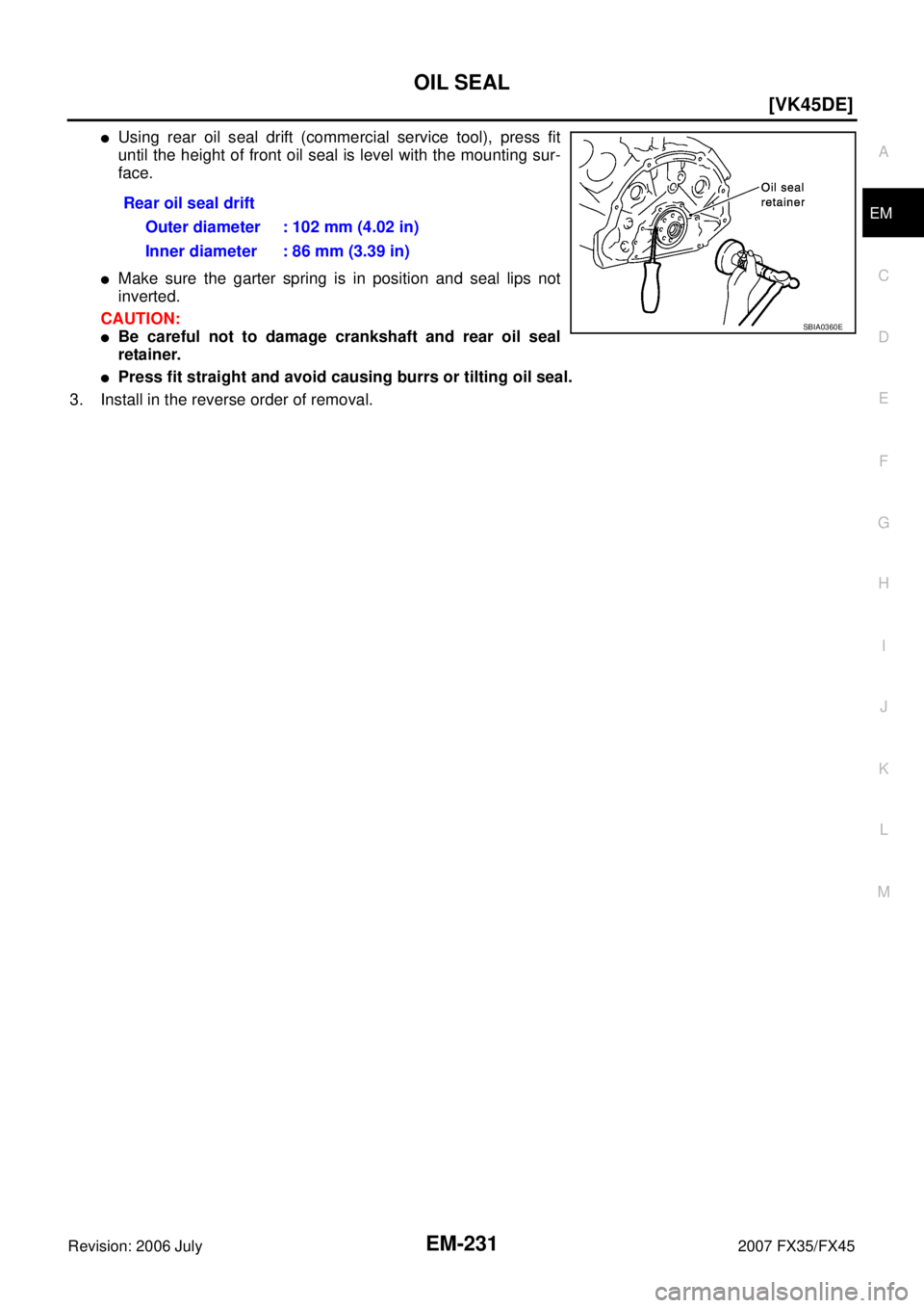
�Using rear oil seal drift (commercial service tool), press fit
until the height of front oil seal is level with the mounting sur-
face.
�Make sure the garter spring is in position and seal lips not
inverted.
CAUTION:
�Be careful not to damage crankshaft and rear oil seal
retainer.
�Press fit straight and avoid causing burrs or tilting oil seal.
3. Install in the reverse order of removal. Rear oil seal drift
Outer diameter : 102 mm (4.02 in)
Inner diameter : 86 mm (3.39 in)
SBIA0360E
Page 3024 of 4366
![INFINITI FX35 2007 Service Manual EM-232
[VK45DE]
CYLINDER HEAD
Revision: 2006 July 2007 FX35/FX45
CYLINDER HEADPFP:11041
On-Vehicle ServiceNBS003IJ
CHECKING COMPRESSION PRESSURE
1. Warm up engine thoroughly. Then, stop it.
2. Releas](/manual-img/42/57018/w960_57018-3023.png "INFINITI FX35 2007 Service Manual EM-232
[VK45DE]
CYLINDER HEAD
Revision: 2006 July 2007 FX35/FX45
CYLINDER HEADPFP:11041
On-Vehicle ServiceNBS003IJ
CHECKING COMPRESSION PRESSURE
1. Warm up engine thoroughly. Then, stop it.
2. Releas")
EM-232
[VK45DE]
CYLINDER HEAD
Revision: 2006 July 2007 FX35/FX45
CYLINDER HEADPFP:11041
On-Vehicle ServiceNBS003IJ
CHECKING COMPRESSION PRESSURE
1. Warm up engine thoroughly. Then, stop it.
2. Release fuel pressure. Refer to EC-747, "
FUEL PRESSURE RELEASE" .
a. Remove fuel pump fuse to avoid fuel injection during measure- ment.
3. Remove engine cover with power tool. Refer to EM-173, "
ENGINE ROOM COVER" .
4. Remove ignition coil and spark plug from each cylinder. Refer to EM-191, "
IGNITION COIL" and EM-192,
"SPARK PLUG (PLATINUM-TIPPED TYPE)" .
5. Connect engine tachometer (not required in use of CONSULT-II).
6. Install compression gauge with adapter (SST or commercial ser- vice tool) onto spark plug hole.
�Use compression gauge adapter (SST) which is required on
No. 7 and 8 cylinders.
�Use compression gauge adapter (if no SST is used) whose
picking up end inserted to spark plug hole is smaller than 20
mm (0.79 in) in diameter. Otherwise, it may be caught by cyl-
inder head during removal.
7. With accelerator pedal fully depressed, turn ignition switch to “START” for cranking. When the gauge pointer stabilizes, read the compression pressure and engine rpm. Perform these steps to check each cyl-
inder.
Compression pressure:
Unit: kPa (kg/cm2 , psi) /rpm
CAUTION:
Always use a fully changed battery to obtain the specified engine speed.
PBIB1482E
PBIC1554E
SBIA0533E
Standard Minimum Deferential limit between cylinders
1,320 (13.5, 191) / 300 1,130 (11.5, 164) / 300 98 (1.0, 14) / 300
![INFINITI FX35 2007 Service Manual PREPARATION EM-169
[VK45DE]
C
D E
F
G H
I
J
K L
M A
EM
Revision: 2006 July 2007 FX35/FX45
Commercial Service ToolsNBS003HJ
—
(J-45476)
Ring gear stopper Removing and installing crank](/manual-img/42/57018/w960_57018-2960.png "INFINITI FX35 2007 Service Manual PREPARATION EM-169
[VK45DE]
C
D E
F
G H
I
J
K L
M A
EM
Revision: 2006 July 2007 FX35/FX45
Commercial Service ToolsNBS003HJ
—
(J-45476)
Ring gear stopper Removing and installing crank")