Page 4226 of 4366
NDS000A5
FUNCTION
CONSULT-II can displa")
TF-22
TROUBLE DIAGNOSIS
Revision: 2006 July 2007 FX35/FX45
*: The values are changed by throttle opening and engine speed.
CONSULT-II Function (ALL MODE AWD/4WD)NDS000A5
FUNCTION
CONSULT-II can display each diagnostic item using the diagnostic test modes shown following.
CONSULT-II SETTING PROCEDURE
Refer to GI-38, "CONSULT-II Start Procedure" .
SELF-DIAG RESULT MODE
Operation Procedure
1. Perform “CONSULT-II Start Procedure”. Refer to GI-38, "CONSULT-II Start Procedure" .
2. Start engine and drive at 30 km/h (19 MPH) or more for approx. 1 minute.
3. Stop vehicle. With engine at idle, touch “SELF-DIAG RESULTS”. Display shows malfunction experienced since the last erasing
operation.
NOTE:
�The details for “TIME” are as follow:
–“0”: Error currently detected with AWD control unit.
–Except for “0”: Error detected in the past and memorized
with AWD control unit.
Detects frequency of driving after DTC occurs (frequency
of turning ignition switch “ON”).
Display Item List
P BRAKE SW
(ON/OFF) Condition of parking brake Parking brake operated ON
Parking brake not operated OFF
Monitored item [Unit] Content Condition Display value
Diagnostic test mode Function
Reference
page
Self-diagnostic results
�Self-diagnostic results can be read and erased quickly. TF-22
Data monitor�Input/Output data in the AWD control unit can be read.TF-24
CAN diagnostic support monitor�The results of transmit/receive diagnosis of CAN communication can be read.LAN-44
Active test�Diagnostic Test Mode in which CONSULT-II drives some actuators apart from
the AWD control unit and also shifts some parameters in a specified range. TF-25
ECU part number�AWD control unit part number can be read.
TF-25
SDIA2217E
Items (CONSULT-II screen
terms) Diagnostic item is detected when... Check item
CONTROLLER FAILURE
[C1201] Malfunction has occurred inside AWD control unit.
TF-27, "
AWD Control Unit"
ABS SYSTEM
[C1203] Malfunction related to wheel sensor has been detected by ABS actu-
ator and electric unit (control unit). TF-27, "ABS System"
4WD SOLENOID
[C1204] Malfunction related to AWD solenoid has been detected.
TF-28, "AWD Solenoid"
4WD ACTUATOR RLY
[C1205] Malfunction has been detected from AWD actuator relay integrated
with AWD control unit, or malfunction related to AWD solenoid has
been detected. TF-31, "AWD Actuator
Relay" or
TF-28, "AWD
Solenoid"
ENGINE SIGNAL 1
[C1210] Malfunction has been detected from ECM. TF-32, "Engine Control Sig-
nal"
CAN COMM CIRCUIT
[U1000] When AWD control unit is not transmitting or receiving CAN commu-
nication signal for 2 seconds or more. TF-32, "CAN Communica-
tion Line"
NO DTC IS DETECTED.
FURTHER TESTING MAY BE
REQUIRED. No NG item has been detected. —
Page 4228 of 4366

TF-24
TROUBLE DIAGNOSIS
Revision: 2006 July 2007 FX35/FX45
DATA MONITOR MODE
Operation Procedure
1. Perform “CONSULT-II Start Procedure”. Refer to GI-38, "CONSULT-II Start Procedure" .
2. Touch “DATA MONITOR”.
3. Select from “SELECT MONITOR ITEM”, screen of data monitor mode is displayed. NOTE:
When malfunction is detected, CONSULT-II performs REAL-TIME DIAGNOSIS.
Also, any malfunction detected while in this mode will be displayed at real time.
Display Item List
× : Standard –: Not applicable
Monitored item (Unit) Monitor item selection
Remarks
ECU INPUT
SIGNALS MAIN
SIGNALS SELECTION
FROM MENU
FR RH SENSOR
(km/h) or (mph) ××× Wheel speed calculated by front wheel sensor RH
signal is displayed.
FR LH SENSOR
(km/h) or (mph) ××× Wheel speed calculated by front wheel sensor LH
signal is displayed.
RR RH SENSOR
(km/h) or (mph) ×××
Wheel speed calculated by rear wheel sensor RH
signal is displayed.
RR LH SENSOR
(km/h) or (mph) ××× Wheel speed calculated by rear wheel sensor LH
signal is displayed.
BATTERY VOLT
(V) ––
×Power supply voltage for AWD control unit
THRTL POS SEN
(%) ––
×Throttle opening status is displayed.
ETS SOLENOID
(A) ––
×Monitored value of current at AWD solenoid
STOP LAMP SW
(ON/OFF) ––
× Stop lamp switch signal status via CAN communica-
tion line is displayed.
ENG SPEED SIG
(RUN/STOP) ––
×Engine status is displayed.
ETS ACTUATOR
(ON/OFF) ––
× Operating condition of AWD actuator relay (inte-
grated in AWD control unit) is displayed.
4WD WARN LAMP
(ON/OFF) ––
×Control status of AWD warning lamp is displayed.
4WD MODE SW
(AUTO) ––
×AWD lock switch is not equipped, but displayed.
4WD MODE MON
(AUTO) ––
×Control status of AWD is displayed.
DIS-TIRE MONI
(mm) ––
×Improper size tire installed condition is displayed.
P BRAKE SW
(ON/OFF) ––
× Parking switch signal status via CAN communica-
tion line is displayed.
Voltage
(V) ––
× The value measured by the voltage probe is dis-
played.
Page 4229 of 4366

TROUBLE DIAGNOSIS TF-25
C E F
G H
I
J
K L
M A
B
TF
Revision: 2006 July 2007 FX35/FX45
ACTIVE TEST MODE
Description
Use this mode to determine and identify the details of a malfunction based on self-diagnostic results or data
monitor. AWD control unit gives drive signal to actuator with receiving command from CONSULT-II to check
operation of actuator.
Test Item
CAUTION:
Do not continuously energize for a long time.
AWD CONTROL UNIT PART NUMBER
Ignore the AWD control unit part number displayed in the “ECU PART NUMBER”.
Refer to parts catalog to order the AWD control unit.
Frequency
(Hz) ––
×
The value measured by the pulse probe is dis-
played.
DUTY-HI (high)
(%) ––
×
DUTY-LOW (low)
(%) ––
×
PLS WIDTH-HI
(msec) ––
×
PLS WIDTH-LOW
(msec) ––
×
Monitored item (Unit)
Monitor item selection
Remarks
ECU INPUT
SIGNALS MAIN
SIGNALS SELECTION
FROM MENU
Test item Condition Description
ETS S/V
(Detects AWD solenoid valve)
�Vehicle stopped
�Engine running
�No DTC detected
�Change command current value to AWD solenoid, and then change driv-
ing mode. (Monitor value is normal if it is within approximately ±10% of
command value.)
Qu: Increase current value in increments of 0.20A
Qd: Decrease current value in increments of 0.20A
UP: Increase current value in increments of 0.02A
DOWN: Decrease current value in increments of 0.02A
Page 4248 of 4366

TF-44
TRANSFER ASSEMBLY
Revision: 2006 July 2007 FX35/FX45
TRANSFER ASSEMBLYPFP:33100
Removal and InstallationNDS000AN
REMOVAL
1. Remove tunnel stay with power tool. Refer to RSU-7, "Removal and installation" .
2. Remove exhaust front tube with power tool. Refer to EX-3, "
EXHAUST SYSTEM" .
3. Remove front and rear propeller shaft. Refer to PR-4, "
FRONT PROPELLER SHAFT" and PR-7, "REAR
PROPELLER SHAFT" .
4. Disconnect transfer assembly harness connector and separate harness from transfer assembly.
5. Remove air breather hose. Refer to TF-43, "
AIR BREATHER HOSE" .
6. Support transfer assembly and transmission assembly with a jack.
7. Remove engine rear member with power tool. Refer to EM-113, "
ENGINE ASSEMBLY" (VQ35DE) or
EM-243, "
ENGINE ASSEMBLY" (VK45DE).
8. Remove transfer mounting bolts and separate transfer from transmission. CAUTION:
Secure transfer assembly to a jack.
INSTALLATION
Note the following, and install in the reverse order of removal.
�When installing the transfer to the transmission, install the
mounting bolts following the standard below.
�After the installation, check the fluid level and for fluid leakage.
Refer to TF-9, "
Inspection" .
Bolt No. 1 2 3 4
Quantity 4 3 2 1
Bolt length “ ” mm (in) 75 (2.95) 45 (1.77) 40 (1.57) 30 (1.18)
Tightening torque
N·m (kg-m, ft-lb) 37 (3.8, 27)
SDIA2284E
Page 4294 of 4366
WT-30
TROUBLE DIAGNOSES
Revision: 2006 July 2007 FX35/FX45
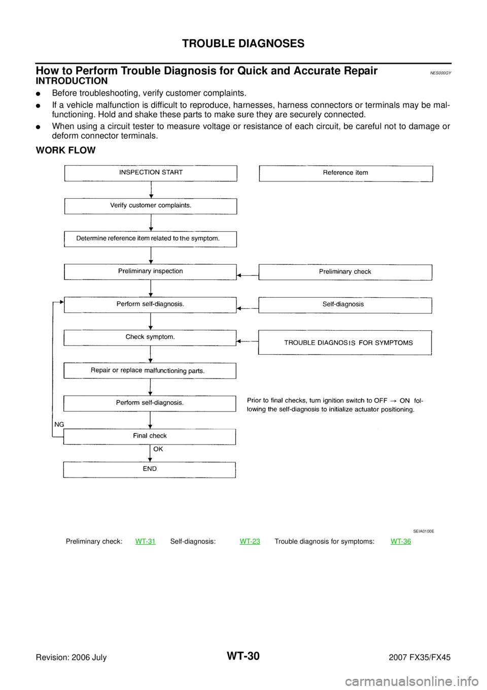
How to Perform Trouble Diagnosis for Quick and Accurate RepairNES000GY
INTRODUCTION
�Before troubleshooting, verify customer complaints.
�If a vehicle malfunction is difficult to reproduce, harnesses, harness connectors or terminals may be mal-
functioning. Hold and shake these parts to make sure they are securely connected.
�When using a circuit tester to measure voltage or resistance of each circuit, be careful not to damage or
deform connector terminals.
WORK FLOW
Preliminary check: WT-31Self-diagnosis:WT-23Trouble diagnosis for symptoms: WT-36
SEIA0100E