Page 661 of 4366

INTEGRATED DISPLAY SYSTEM AV-55
C
D E
F
G H
I
J
L
M A
B
AV
Revision: 2006 July 2007 FX35/FX45
Component DescriptionNKS003J0
DISPLAY CONTROL UNIT
�Display control unit draws a status of the audio and air condi-
tioner, a TRIP screen, a FUEL ECONOMY screen, etc., and
transmits the image signals to the display screen.
�It receives operation signals of audio and air conditioner from A/
C and AV switch, and transmits the operation signal of audio to
the audio unit via the communication line and transmits the
operation signal of air conditioner to the meter and A/C amp. via
CAN communication.
DISPLAY
�Images on the display include RGB image such as map screen.
�Display control unit controls images on the display.
A/C AND AV SWITCH
�A/C and AV switch, an integrated combination of audio and air
conditioner switches, are adopted.
�Operation signal of audio is transmitted to the audio unit through
display control unit with the communication line. Operation sig-
nal of air conditioner is transmitted to meter and A/C amp.
through display control unit with CAN communication.
CAN Communication UnitNKS003J1
Refer to LAN-49, "CAN System Specification Chart" .
Component Parts LocationNKS003J2
SKIB8638E
SKIB8639E
SKIB8639E
SKIB8645E
Page 688 of 4366
AV-82
INTEGRATED DISPLAY SYSTEM
Revision: 2006 July 2007 FX35/FX45
A/C and AV Switch Self-Diagnosis FunctionNKS003JG
Performing self-diagnosis makes it possible to check operation of A/C and AV switch indicator (LED) and other
switch.
STARTING THE SELF-DIAGNOSIS MODE
1. Turn ignition switch from OFF to ACC.
2. Within 10 seconds press and hold the switches “1” and “6” simultaneously for 3 seconds.
DIAGNOSIS FUNCTION
The following are checked:
�All the indicators (LED) in the A/C and AV switch.
�Continuity of the switches by sounding the buzzer when the A/C and AV switch and audio steering wheel
switch is pressed.
�Continuity of harness between A/C and AV switch and audio steering wheel switch.
NOTE:
Rear window defogger switch operation is not checked (No beep sound even under normal status).
EXITING THE SELF-DIAGNOSIS MODE
�Turn ignition switch OFF.
SKIB8744E
Page 704 of 4366
AV-98
NAVIGATION SYSTEM
Revision: 2006 July 2007 FX35/FX45
DISPLAY
�Images on the display include RGB image such as map screen.
�Display control unit controls images on the display.
A/C AND AV SWITCH
�A/C and AV switch, an integrated combination of audio and air
conditioner switches, are adopted.
�Operation signal of audio is transmitted to the audio unit through
display control unit with the communication line. Operation sig-
nal of air conditioner is transmitted to meter and A/C amp.
through display control unit with CAN communication.
CAN Communication UnitNKS003K2
Refer to LAN-49, "CAN System Specification Chart" .
Component Parts LocationNKS003K3
SKIB8639E
SKIB8639E
SKIB8641E
Page 743 of 4366
NAVIGATION SYSTEM AV-137
C
D E
F
G H
I
J
L
M A
B
AV
Revision: 2006 July 2007 FX35/FX45
A/C and AV Switch Self-Diagnosis FunctionNKS003KJ
Performing self-diagnosis makes it possible to check operation of A/C and AV switch indicator (LED) and other
switch.
STARTING THE SELF-DIAGNOSIS MODE
1. Turn ignition switch from OFF to ACC.
2. Within 10 seconds press and hold the switches “1” and “6” simultaneously for 3 seconds.
DIAGNOSIS FUNCTION
The following are checked:
�All the indicators (LED) in the A/C and AV switch.
�Continuity of the switches by sounding the buzzer when the A/C and AV switch and audio steering wheel
switch is pressed.
�Continuity of harness between A/C and AV switch and audio steering wheel switch.
NOTE:
Rear window defogger switch operation is not checked (No beep sound even under normal status).
EXITING THE SELF-DIAGNOSIS MODE
�Turn ignition switch OFF.
SKIB8660E
Page 775 of 4366

INFINITI MOBILE ENTERTAINMENT SYSTEM AV-169
C
D E
F
G H
I
J
L
M A
B
AV
Revision: 2006 July 2007 FX35/FX45
3. CHECK HARNESS
1. Turn ignition switch OFF.
2. Disconnect DVD player and DVD display connectors.
3. Check continuity between DVD player harness connector B19 terminals 17, 18, 19, 20 and DVD display harness connector
B61 terminals 1, 2, 3, 4.
4. Check continuity between DVD player harness connector B19 terminals 17, 18, 19, 20 and ground.
OK or NG
OK >> GO TO 4.
NG >> Repair harness or connector.
4. CHECK MES SOUND SIGNAL
1. Connect DVD player and DVD display connectors.
2. Turn the ignition switch ACC and Press “POWER” switch of DVD player.
3. Check the signal between DVD player harness connector B19 terminals 17, 18, 20 and 19 with CONSULT-II or oscilloscope.
OK or NG
OK >> Replace DVD display.
NG >> Replace DVD player.
Remote Controller Does Not WorkNKS003EB
1. CHECK DVD PLAYER OPERATION SWITCH
1. Turn ignition switch ACC.
2. Press “POWER” switch of DVD player and operate DVD player switch.
Dose the DVD player switches work?
YES >> Replace remote controller.
NO >> GO TO 2. 17 – 1 : Continuity should exist.
18 – 2 : Continuity should exist.
19 – 3 : Continuity should exist.
20 – 4 : Continuity should exist.
17, 18, 19, 20 – Ground : Continuity should not exist.
SKIA7033E
Te r m i n a l Condition Reference value
(+) (–)
17 19 Play CD or DVD video. Refer to
AV-161, "
Terminals and
Reference Value for DVD Player" .
18
20
SKIA7047E
Page 800 of 4366

BCS-2
PRECAUTIONS
Revision: 2006 July 2007 FX35/FX45
PRECAUTIONSPFP:00001
Precautions for Supplemental Restraint System (SRS) “AIR BAG” and “SEAT
BELT PRE-TENSIONER”
NKS0033Y
The Supplemental Restraint System such as “AIR BAG” and “SEAT BELT PRE-TENSIONER”, used along
with a front seat belt, helps to reduce the risk or severity of injury to the driver and front passenger for certain
types of collision. This system includes seat belt switch inputs and dual stage front air bag modules. The SRS
system uses the seat belt switches to determine the front air bag deployment, and may only deploy one front
air bag, depending on the severity of a collision and whether the front occupants are belted or unbelted.
Information necessary to service the system safely is included in the SRS and SB section of this Service Man-
ual.
WARNING:
�To avoid rendering the SRS inoperative, which could increase the risk of personal injury or death
in the event of a collision which would result in air bag inflation, all maintenance must be per-
formed by an authorized NISSAN/INFINITI dealer.
�Improper maintenance, including incorrect removal and installation of the SRS, can lead to per-
sonal injury caused by unintentional activation of the system. For removal of Spiral Cable and Air
Bag Module, see the SRS section.
�Do not use electrical test equipment on any circuit related to the SRS unless instructed to in this
Service Manual. SRS wiring harnesses can be identified by yellow and/or orange harnesses or
harness connectors.
Page 801 of 4366

BCM (BODY CONTROL MODULE) BCS-3
C
D E
F
G H
I
J
L
M A
B
BCS
Revision: 2006 July 2007 FX35/FX45
BCM (BODY CONTROL MODULE)PFP:284B2
System DescriptionNKS0033Z
BCM (Body Control Module) controls the operation of various electrical units installed on the vehicle.
BCM FUNCTION
BCM has combination switch reading function for reading the operation of combination switches (light, wiper,
washer and turn signal) in addition to a function for controlling the operation of various electrical components.
Also it has an interface function allowing it to receive signals from the unified meter and A/C amp., and send
signals to ECM using CAN communication.
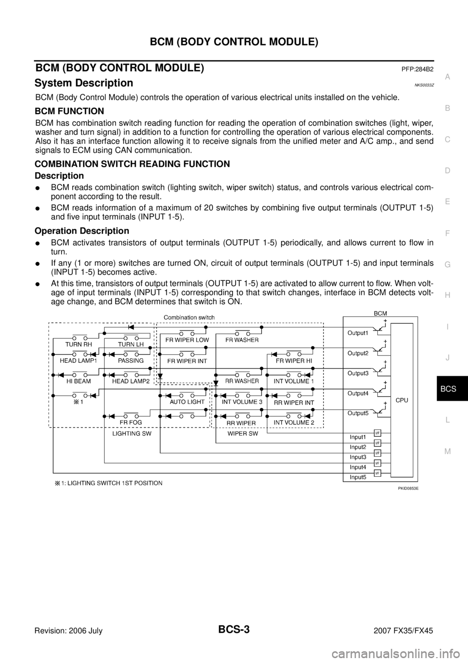
COMBINATION SWITCH READING FUNCTION
Description
�BCM reads combination switch (lighting switch, wiper switch) status, and controls various electrical com-
ponent according to the result.
�BCM reads information of a maximum of 20 switches by combining five output terminals (OUTPUT 1-5)
and five input terminals (INPUT 1-5).
Operation Description
�BCM activates transistors of output terminals (OUTPUT 1-5) periodically, and allows current to flow in
turn.
�If any (1 or more) switches are turned ON, circuit of output terminals (OUTPUT 1-5) and input terminals
(INPUT 1-5) becomes active.
�At this time, transistors of output terminals (OUTPUT 1-5) are activated to allow current to flow. When volt-
age of input terminals (INPUT 1-5) corresponding to that switch changes, interface in BCM detects volt-
age change, and BCM determines that switch is ON.
PKID0853E
Page 802 of 4366

BCS-4
BCM (BODY CONTROL MODULE)
Revision: 2006 July 2007 FX35/FX45
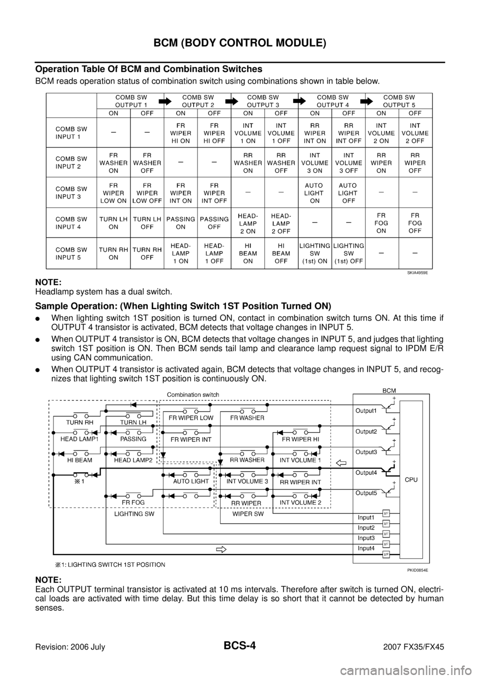
Operation Table Of BCM and Combination Switches
BCM reads operation status of combination switch using combinations shown in table below.
NOTE:
Headlamp system has a dual switch.
Sample Operation: (When Lighting Switch 1ST Position Turned ON)
�When lighting switch 1ST position is turned ON, contact in combination switch turns ON. At this time if
OUTPUT 4 transistor is activated, BCM detects that voltage changes in INPUT 5.
�When OUTPUT 4 transistor is ON, BCM detects that voltage changes in INPUT 5, and judges that lighting
switch 1ST position is ON. Then BCM sends tail lamp and clearance lamp request signal to IPDM E/R
using CAN communication.
�When OUTPUT 4 transistor is activated again, BCM detects that voltage changes in INPUT 5, and recog-
nizes that lighting switch 1ST position is continuously ON.
NOTE:
Each OUTPUT terminal transistor is activated at 10 ms intervals. Therefore after switch is turned ON, electri-
cal loads are activated with time delay. But this time delay is so short that it cannot be detected by human
senses.
SKIA4959E
PKID0854E