Page 4283 of 4366
TROUBLE DIAGNOSES WT-19
C
D
F
G H
I
J
K L
M A
B
WT
Revision: 2006 July 2007 FX35/FX45
Control Unit Input/Output Signal StandardNES000GU
Standards using a circuit tester and oscilloscope
Terminal
Item Condition Voltage (V)
Approx. value
+ (wire color) –
15 (G)
Ground Tire pressure warning check
connector Always 5V
18 (B) Remote keyless entry receiver
(Ground) —0V
19 (R) Remote keyless entry receiver
(Power supply) Stand-by
Press any of the keyfob
switches
20 (Y) Remote keyless entry receiver
(Signal) Stand-by
Press any of the keyfob
switches
38 (W/L) Ignition switch Ignition switch ON or START Battery voltage (12V) 39 (L) CAN-H — —
40 (P) CAN-L — —
42 (L/R) Battery power supply (Fuse) Always Battery voltage (12V)
45 (G/W) Turn signal (left)
�Ignition switch ON
�Combination switch is turn
signal (left)
OCC3879D
OCC3882D
OCC3881D
OCC3880D
SKIA3009J
Page 4309 of 4366

PRECAUTION WW-3
C
D E
F
G H
I
J
L
M A
B
WW
Revision: 2006 July 2007 FX35/FX45
PRECAUTIONPFP:00011
Precautions for Supplemental Restraint System (SRS) “AIR BAG” and “SEAT
BELT PRE-TENSIONER”
NKS00325
The Supplemental Restraint System such as “AIR BAG” and “SEAT BELT PRE-TENSIONER”, used along
with a front seat belt, helps to reduce the risk or severity of injury to the driver and front passenger for certain
types of collision. This system includes seat belt switch inputs and dual stage front air bag modules. The SRS
system uses the seat belt switches to determine the front air bag deployment, and may only deploy one front
air bag, depending on the severity of a collision and whether the front occupants are belted or unbelted.
Information necessary to service the system safely is included in the SRS and SB section of this Service Man-
ual.
WARNING:
�To avoid rendering the SRS inoperative, which could increase the risk of personal injury or death
in the event of a collision which would result in air bag inflation, all maintenance must be per-
formed by an authorized NISSAN/INFINITI dealer.
�Improper maintenance, including incorrect removal and installation of the SRS, can lead to per-
sonal injury caused by unintentional activation of the system. For removal of Spiral Cable and Air
Bag Module, see the SRS section.
�Do not use electrical test equipment on any circuit related to the SRS unless instructed to in this
Service Manual. SRS wiring harnesses can be identified by yellow and/or orange harnesses or
harness connectors.
Page 4311 of 4366

FRONT WIPER AND WASHER SYSTEM WW-5
C
D E
F
G H
I
J
L
M A
B
WW
Revision: 2006 July 2007 FX35/FX45
�to front wiper relay, located in IPDM E/R
�to front wiper high relay, located in IPDM E/R and
�to CPU located in IPDM E/R,
�through 10 A fuse (No. 84, located in IPDM E/R)
�through IPDM E/R terminal 44
�to combination switch terminal 14.
Ground is supplied
�to BCM terminals 49 and 52
�through grounds M35, M45 and M85,
�to IPDM E/R terminals 38 and 60
�through grounds E21, E50 and E51,
�to combination switch terminal 12
�through grounds M35, M45 and M85.
LOW SPEED WIPER OPERATION
When wiper switch is in LOW position, BCM detects low speed wiper ON signal by BCM wiper switch reading
function.
BCM sends front wiper request signal (LO) through CAN communication
�from BCM terminals 39 and 40
�to IPDM E/R terminals 48 and 49.
When IPDM E/R receives front wiper request signal (LO), it turns ON front wiper relay located in IPDM E/R,
power is supplied
�through front wiper relay
�through front wiper high relay
�through IPDM E/R terminal 21
�to front wiper motor terminal 1.
Ground is supplied
�to front wiper motor terminal 2
�through grounds E21, E50 and E51.
With power and ground supplied, the front wiper motor operates at low speed.
HIGH SPEED WIPER OPERATION
When wiper switch is in HI position, BCM detects high speed wiper ON signal by BCM wiper switch reading
function.
BCM sends front wiper request signal (HI) through CAN communication
�from BCM terminals 39 and 40
�to IPDM E/R terminals 48 and 49.
When IPDM E/R receives front wiper request signal (HI), it turns ON front wiper relay (located in IPDM E/R),
power is supplied
�through front wiper relay
�through front wiper high relay
�through IPDM E/R terminal 31
�to front wiper motor terminal 4.
Ground is supplied
�to front wiper motor terminal 2
�through grounds E21, E50 and E51.
With power and ground supplied, the front wiper motor operates at high speed.
INTERMITTENT OPERATION
Front wiper intermittent operation delay interval is determined from a combination of 3 switches (intermittent
operation dial position 1, 2, and 3) and vehicle speed signal.
Speed dependent wiper controlled mode can be changed by the function setting of CONSULT-ll or display.
During each intermittent operation delay interval, BCM sends front wiper request signal to IPDM E/R.
Page 4314 of 4366

WW-8
FRONT WIPER AND WASHER SYSTEM
Revision: 2006 July 2007 FX35/FX45
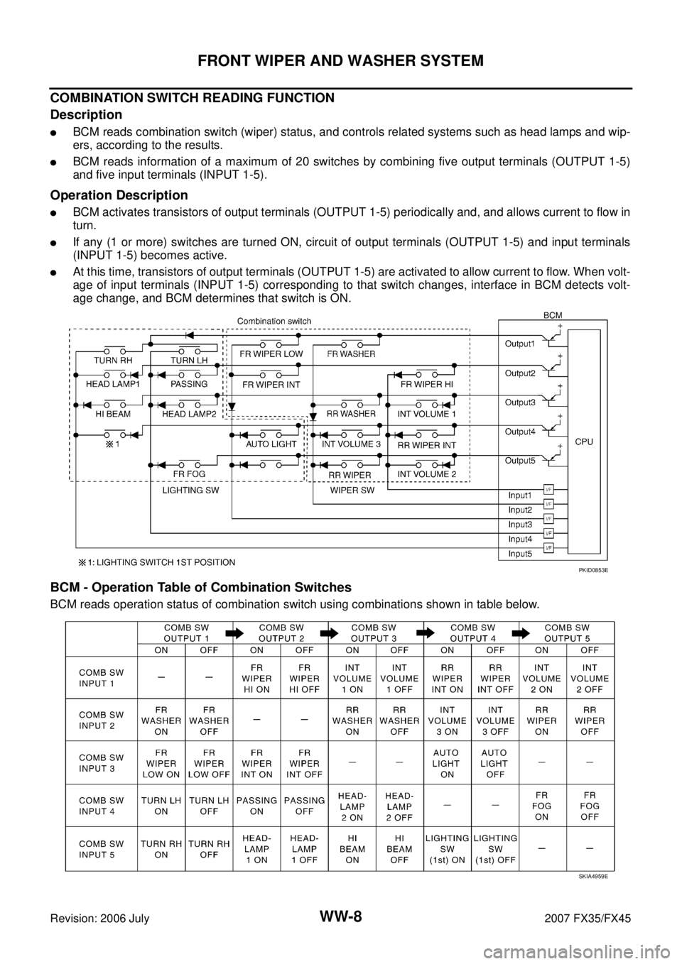
COMBINATION SWITCH READING FUNCTION
Description
�BCM reads combination switch (wiper) status, and controls related systems such as head lamps and wip-
ers, according to the results.
�BCM reads information of a maximum of 20 switches by combining five output terminals (OUTPUT 1-5)
and five input terminals (INPUT 1-5).
Operation Description
�BCM activates transistors of output terminals (OUTPUT 1-5) periodically and, and allows current to flow in
turn.
�If any (1 or more) switches are turned ON, circuit of output terminals (OUTPUT 1-5) and input terminals
(INPUT 1-5) becomes active.
�At this time, transistors of output terminals (OUTPUT 1-5) are activated to allow current to flow. When volt-
age of input terminals (INPUT 1-5) corresponding to that switch changes, interface in BCM detects volt-
age change, and BCM determines that switch is ON.
BCM - Operation Table of Combination Switches
BCM reads operation status of combination switch using combinations shown in table below.
PKID0853E
SKIA4959E