Page 4054 of 4366

SE-16
AUTOMATIC DRIVE POSITIONER
Revision: 2006 July 2007 FX35/FX45
CAN Communication System DescriptionNIS001UQ
CAN (Controller Area Network) is a serial communication line for real time application. It is an on-vehicle mul-
tiplex communication line with high data communication speed and excellent error detection ability. Many elec-
tronic control units are equipped onto a vehicle, and each control unit shares information and links with other
control units during operation (not independent). In CAN communication, control units are connected with 2
communication lines (CAN H line, CAN L line) allowing a high rate of information transmission with less wiring.
Each control unit transmits/receives data but selectively reads required data only.
CAN Communication UnitNIS001UR
Refer to LAN-49, "CAN System Specification Chart" .
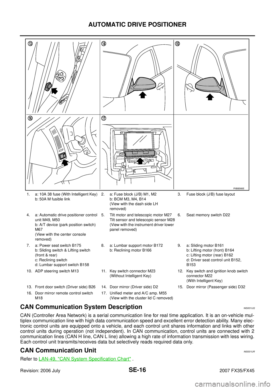
1. a: 10A 38 fuse (With Intelligent Key)
b: 50A M fusible link 2. a: Fuse block (J/B) M1, M2
b: BCM M3, M4, B14
(View with the dash side LH
removed) 3. Fuse block (J/B) fuse layout
4. a: Automatic drive positioner control unit M49, M50
b: A/T device (park position switch)
M67
(View with the center console
removed) 5. Tilt motor and telescopic motor M27
Tilt sensor and telescopic sensor M28
(View with the instrument driver lower
panel removed) 6. Seat memory switch D22
7. a: Power seat switch B175 b: Sliding switch & Lifting switch
(front & rear)
c: Reclining switch
d: Lumbar support switch B158 8. a: Lumbar support motor B172
b: Reclining motor B166 9. a: Sliding motor B161
b: Lifting motor (front) B164
c: Lifting motor (rear) B162
d: Driver seat control unit B152,
B153
10. ADP steering switch M13 11. Key switch connector M23 (Without Intelligent Key) 12. Key switch and ignition knob switch
connector M22
(With Intelligent Key)
13. Front door switch (Driver side) B26 14. Door mirror (Driver side) D2 15. Door mirror (Passenger side) D32
16. Door mirror remote control switch M18 17. Unified meter and A/C amp. M55
(View with the cluster lid C removed)
PIIB8566E
Page 4083 of 4366

AUTOMATIC DRIVE POSITIONER SE-45
C
D E
F
G H
J
K L
M A
B
SE
Revision: 2006 July 2007 FX35/FX45
Check Reclining Motor CircuitNIS001V3
1. CHECK SEAT RECLINING MECHANISM
Check the following.
�Operation malfunction caused by an interference with the center pillar or center console
�Operation malfunction and interference with other parts by poor installation
OK or NG
OK >>�GO TO 2 (With CONSULT-II).
�GO TO 3 (Without CONSULT-II).
NG >> Repair the malfunctioning part and check again.
2. CHECK FUNCTION
With CONSULT-II
Check operation with “SEAT RECLINING” in ACTIVE TEST.
OK or NG
OK >> Reclining motor circuit is OK.
NG >> GO TO 3.
3. CHECK RECLINING MOTOR HARNESS CONTINUITY
1. Turn ignition switch OFF.
2. Disconnect driver seat control unit connector and reclining motor connector.
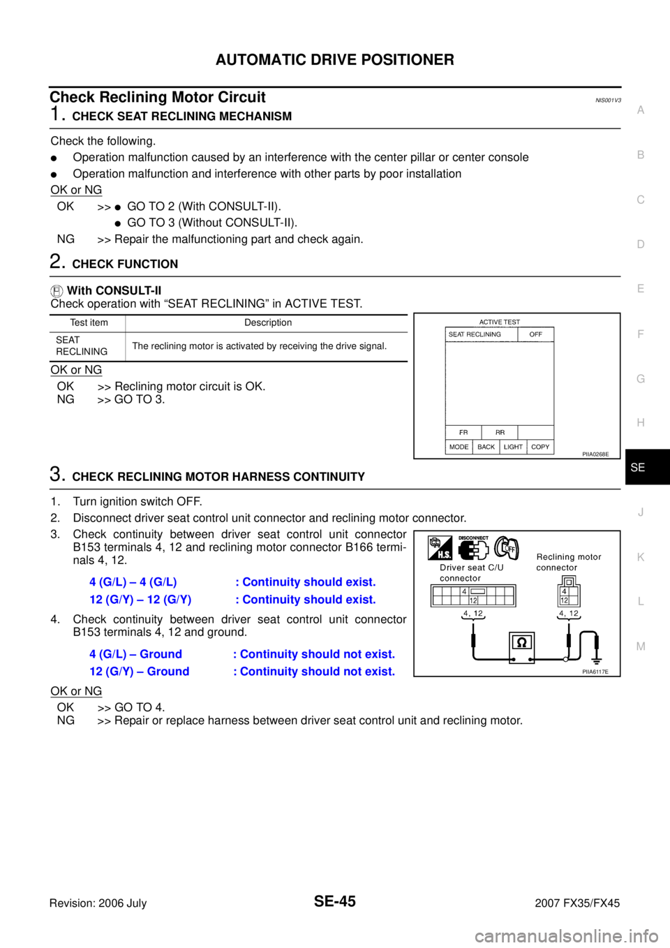
3. Check continuity between driver seat control unit connector B153 terminals 4, 12 and reclining motor connector B166 termi-
nals 4, 12.
4. Check continuity between driver seat control unit connector B153 terminals 4, 12 and ground.
OK or NG
OK >> GO TO 4.
NG >> Repair or replace harness between driver seat control unit and reclining motor.
Test item Description
SEAT
RECLINING The reclining motor is activated by receiving the drive signal.
PIIA0268E
4 (G/L) – 4 (G/L) : Continuity should exist.
12 (G/Y) – 12 (G/Y) : Continuity should exist.
4 (G/L) – Ground : Continuity should not exist.
12 (G/Y) – Ground : Continuity should not exist.
PIIA6117E
Page 4199 of 4366

DIAGNOSIS SENSOR UNIT SRS-53
C
D E
F
G
I
J
K L
M A
B
SRS
Revision: 2006 July 2007 FX35/FX45
DIAGNOSIS SENSOR UNITPFP:28556
Removal and InstallationNHS0007S
REMOVAL
CAUTION:
�Before servicing SRS, turn ignition switch OFF, disconnect both battery cables and wait at least 3
minutes.
�Do not use air tools or electric tools for servicing.
1. Disconnect each harness connector for the air bag module and seat belt pre-tensioner.
2. Remove center console. Refer to IP-11, "
Removal and Installation" .
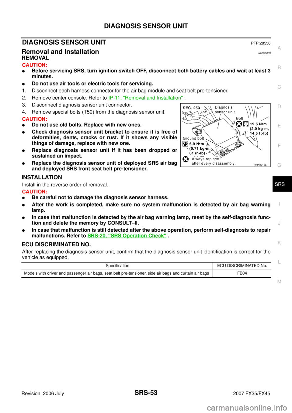
3. Disconnect diagnosis sensor unit connector.
4. Remove special bolts (T50) from the diagnosis sensor unit.
CAUTION:
�Do not use old bolts. Replace with new ones.
�Check diagnosis sensor unit bracket to ensure it is free of
deformities, dents, cracks or rust. If it shows any visible
things of damage, replace with new one.
�Replace diagnosis sensor unit if it has been dropped or
sustained an impact.
�Replace the diagnosis sensor unit of deployed SRS air bag
and deployed SRS front seat belt pre-tensioner.
INSTALLATION
Install in the reverse order of removal.
CAUTION:
�Be careful not to damage the diagnosis sensor harness.
�After the work is completed, make sure no system malfunction is detected by air bag warning
lamp.
�In case that malfunction is detected by the air bag warning lamp, reset by the self-diagnosis func-
tion and delete the memory by CONSULT −ll.
�In case that malfunction is still detected after the above operation, perform self-diagnosis to repair
malfunctions. Refer to SRS-20, "
SRS Operation Check" .
ECU DISCRIMINATED NO.
After replacing the diagnosis sensor unit, confirm that the diagnosis sensor unit identification is correct for the
vehicle as equipped.
PHIA0315E
Specification ECU DISCRIMINATED No.
Models with driver and passenger air bags, seat belt pre-tensioner, side air bags and curtain air bags FB04
Page 4362 of 4366

WW-56
POWER SOCKET
Revision: 2006 July 2007 FX35/FX45
Removal and Installation of Front Power Socket – 1NKS003N8
REMOVAL
1. Remove A/T console finisher. Refer to IP-10, "INSTRUMENT
PANEL ASSEMBLY" .
2. Remove instrument clock finisher. Refer to IP-10, "
INSTRU-
MENT PANEL ASSEMBLY" .
3. Disconnect power socket connector.
4. Remove inner socket from the ring while pressing the hook on the ring out from square hole.
5. Remove ring from ashtray while pressing pawls.
INSTALLATION
Installation is the reverse order of removal.
Removal and Installation of Front Power Socket – 2NKS0033U
REMOVAL
1. Remove inner socket from the ring. While pressing the hook on the ring out from square hole.
2. Remove ring from power socket finisher while pressing pawls.
3. Disconnect power socket connector.
INSTALLATION
Installation is the reverse order of removal.
Removal and Installation of Rear Power SocketNKS004F1
REMOVAL
1. Remove console rear finisher. Refer to IP-17, "CENTER CON-
SOLE" .
2. Disconnect power socket connector.
3. Remove inner socket from the ring. While pressing the hook on the ring out from square hole.
4. Remove ring from power socket finisher while pressing pawls.
INSTALLATION
Installation is the reverse order of removal.
PKIC9710E
SKIA5096E
SKIA5094E