Page 3704 of 4366

MA-12
RECOMMENDED FLUIDS AND LUBRICANTS
Revision: 2006 July 2007 FX35/FX45
RECOMMENDED FLUIDS AND LUBRICANTSPFP:00000
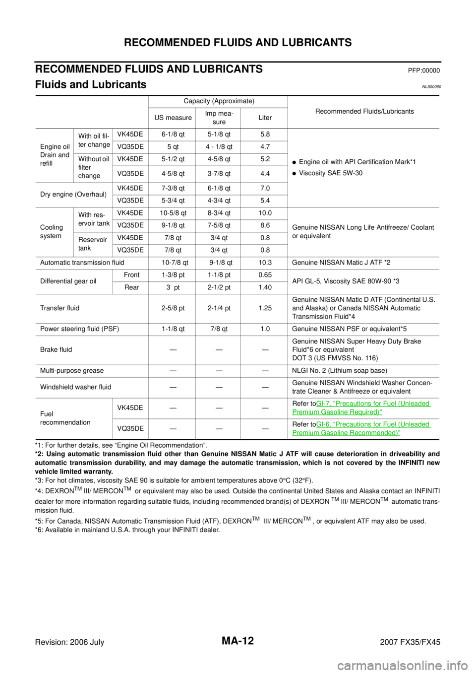
Fluids and Lubricants NLS00060
*1: For further details, see “Engine Oil Recommendation”.
*2: Using automatic transmission fluid other than Genuine NISSAN Matic J ATF will cause deterioration in driveability and
automatic transmission durability, and may damage the automatic transmission, which is not covered by the INFINITI new
vehicle limited warranty.
*3: For hot climates, viscosity SAE 90 is suitable for ambient temperatures above 0 °C (32 °F).
*4: DEXRON
TM III/ MERCONTM or equivalent may also be used. Outside the continental United States and Alaska contact an INFINITI
dealer for more information regarding suitable fluids, including recommended brand(s) of DEXRON TM III/ MERCONTM automatic trans-
mission fluid.
*5: For Canada, NISSAN Automatic Transmission Fluid (ATF), DEXRON
TM III/ MERCONTM , or equivalent ATF may also be used.
*6: Available in mainland U.S.A. through your INFINITI dealer. Capacity (Approximate)
Recommended Fluids/Lubricants
US measure Imp mea-
sure Liter
Engine oil
Drain and
refill With oil fil-
ter change VK45DE 6-1/8 qt 5-1/8 qt 5.8
�Engine oil with API Certification Mark*1
�Viscosity SAE 5W-30
VQ35DE 5 qt 4 - 1/8 qt 4.7
Without oil
filter
change VK45DE 5-1/2 qt 4-5/8 qt 5.2
VQ35DE 4-5/8 qt 3-7/8 qt 4.4
Dry engine (Overhaul) VK45DE 7-3/8 qt 6-1/8 qt 7.0
VQ35DE 5-3/4 qt 4-3/4 qt 5.4
Cooling
system With res-
ervoir tank VK45DE 10-5/8 qt 8-3/4 qt 10.0
Genuine NISSAN Long Life Antifreeze/ Coolant
or equivalent
VQ35DE 9-1/8 qt 7-5/8 qt 8.6
Reservoir
tank VK45DE 7/8 qt 3/4 qt 0.8
VQ35DE 7/8 qt 3/4 qt 0.8
Automatic transmission fluid 10-7/8 qt 9-1/8 qt 10.3 Genuine NISSAN Matic J ATF *2
Differential gear oil Front 1-3/8 pt 1-1/8 pt 0.65
API GL-5, Viscosity SAE 80W-90 *3
Rear 3 pt 2-1/2 pt 1.40
Transfer fluid 2-5/8 pt 2-1/4 pt 1.25 Genuine NISSAN Matic D ATF (Continental U.S.
and Alaska) or Canada NISSAN Automatic
Transmission Fluid*4
Power steering fluid (PSF) 1-1/8 qt 7/8 qt 1.0 Genuine NISSAN PSF or equivalent*5
Brake fluid — — — Genuine NISSAN Super Heavy Duty Brake
Fluid*6 or equivalent
DOT 3 (US FMVSS No. 116)
Multi-purpose grease — — — NLGI No. 2 (Lithium soap base)
Windshield washer fluid — — — Genuine NISSAN Windshield Washer Concen-
trate Cleaner & Antifreeze or equivalent
Fuel
recommendation VK45DE — — —
Refer to
GI-7, "
Precautions for Fuel (Unleaded
Premium Gasoline Required)"
VQ35DE — — — Refer to
GI-6, "Precautions for Fuel (Unleaded
Premium Gasoline Recommended)"
Page 3914 of 4366

RF-12
SUNROOF
Revision: 2006 July 2007 FX35/FX45
ANTI-PINCH FUNCTION
The CPU of sunroof motor monitors the sunroof motor operation and the sunroof position (fully-closed or
other) by the signals from sunroof motor.
When sunroof motor detects an interruption during the following slide close and tilt down operation, sunroof
switch controls the motor for open and the sunroof will operate until full up position (when tilt down operate) or
125 mm (4.92 in) or more in an open direction (when slide close operate).
�close operation and tilt down when ignition switch is in the ON position.
�close operation and tilt down during retained power operation.
MEMORY RESET PROCEDURE
1. Please observe the following instructions while confirming the sunroof operation.
NOTE:
Do not disconnect the electronic power while the sunroof is operating or within 5 seconds after the sunroof
stops. (to wipe-out the memory of lid position and operating friction.)
2. Initialization of system should be conducted after the following conditions.
�When the battery is out or connector is disconnected while sunroof is operating or within 5 seconds
after sunroof stops.
�When the sunroof motor is changed.
�When an emergency handle is used.
�When the sunroof does not operate normally. (Incomplete initialization conditions)
INITIALIZATION PROCEDURE
If the sunroof does not close or open automatically, use the following procedure to return sunroof operation to
normal.
1. Close the sunroof if it is not in the closed position. It may be necessary to repeatedly push the switch to close the sunroof.
2. Press and hold the TILT UP switch. Do not release the switch, keep pressure on it. After 10 seconds of depressing, the sunroof will tilt up, then stop. Release the button.
3. Press and hold the TILT UP switch again. Do not release the switch, keep pressure on it. While depress- ing the switch, the sunroof will “Tilt down” “Slide open” “Slide close”. Release the button after the sunroof
“Tilt down” and stops.
4. Initializing procedure is complete. Confirm proper operation of the sunroof.
CAN Communication System DescriptionNIS001SZ
CAN (Controller Area Network) is a serial communication line for real time application. It is an on-vehicle mul-
tiplex communication line with high data communication speed and excellent error detection ability. Many elec-
tronic control units are equipped onto a vehicle, and each control unit shares information and links with other
control units during operation (not independent). In CAN communication, control units are connected with 2
communication lines (CAN H line, CAN L line) allowing a high rate of information transmission with less wiring.
Each control unit transmits/receives data but selectively reads required data only.
CAN Communication UnitNIS001T0
Refer to LAN-49, "CAN System Specification Chart" .
Page 4054 of 4366

SE-16
AUTOMATIC DRIVE POSITIONER
Revision: 2006 July 2007 FX35/FX45
CAN Communication System DescriptionNIS001UQ
CAN (Controller Area Network) is a serial communication line for real time application. It is an on-vehicle mul-
tiplex communication line with high data communication speed and excellent error detection ability. Many elec-
tronic control units are equipped onto a vehicle, and each control unit shares information and links with other
control units during operation (not independent). In CAN communication, control units are connected with 2
communication lines (CAN H line, CAN L line) allowing a high rate of information transmission with less wiring.
Each control unit transmits/receives data but selectively reads required data only.
CAN Communication UnitNIS001UR
Refer to LAN-49, "CAN System Specification Chart" .
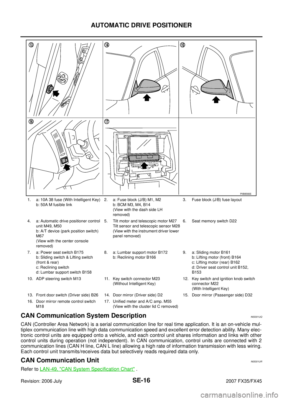
1. a: 10A 38 fuse (With Intelligent Key)
b: 50A M fusible link 2. a: Fuse block (J/B) M1, M2
b: BCM M3, M4, B14
(View with the dash side LH
removed) 3. Fuse block (J/B) fuse layout
4. a: Automatic drive positioner control unit M49, M50
b: A/T device (park position switch)
M67
(View with the center console
removed) 5. Tilt motor and telescopic motor M27
Tilt sensor and telescopic sensor M28
(View with the instrument driver lower
panel removed) 6. Seat memory switch D22
7. a: Power seat switch B175 b: Sliding switch & Lifting switch
(front & rear)
c: Reclining switch
d: Lumbar support switch B158 8. a: Lumbar support motor B172
b: Reclining motor B166 9. a: Sliding motor B161
b: Lifting motor (front) B164
c: Lifting motor (rear) B162
d: Driver seat control unit B152,
B153
10. ADP steering switch M13 11. Key switch connector M23 (Without Intelligent Key) 12. Key switch and ignition knob switch
connector M22
(With Intelligent Key)
13. Front door switch (Driver side) B26 14. Door mirror (Driver side) D2 15. Door mirror (Passenger side) D32
16. Door mirror remote control switch M18 17. Unified meter and A/C amp. M55
(View with the cluster lid C removed)
PIIB8566E