SERVICE INFORMATION FOR ELECTRICAL INCIDENT GI-29
C
D E
F
G H
I
J
K L
M B
GI
Revision: 2006 July 2007 FX35/FX45
�Freezing
�Water intrusion
�Electrical load
�Cold or hot start up
Get a thorough description of the incident from the customer. It is important for simulating the conditions of the
problem.
Vehicle Vibration
The problem may occur or become worse while driving on a rough road or when engine is vibrating (idle with
A/C on). In such a case, you will want to check for a vibration related condition. Refer to the following illustra-
tion.
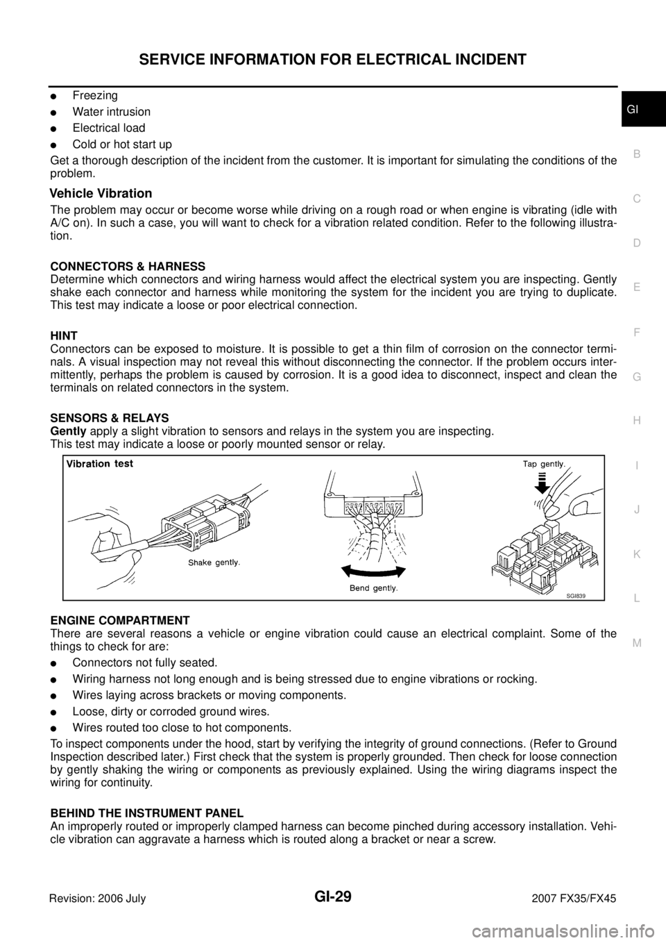
CONNECTORS & HARNESS
Determine which connectors and wiring harness would affect the electrical system you are inspecting. Gently
shake each connector and harness while monitoring the system for the incident you are trying to duplicate.
This test may indicate a loose or poor electrical connection.
HINT
Connectors can be exposed to moisture. It is possible to get a thin film of corrosion on the connector termi-
nals. A visual inspection may not reveal this without disconnecting the connector. If the problem occurs inter-
mittently, perhaps the problem is caused by corrosion. It is a good idea to disconnect, inspect and clean the
terminals on related connectors in the system.
SENSORS & RELAYS
Gently apply a slight vibration to sensors and relays in the system you are inspecting.
This test may indicate a loose or poorly mounted sensor or relay.
ENGINE COMPARTMENT
There are several reasons a vehicle or engine vibration could cause an electrical complaint. Some of the
things to check for are:
�Connectors not fully seated.
�Wiring harness not long enough and is being stressed due to engine vibrations or rocking.
�Wires laying across brackets or moving components.
�Loose, dirty or corroded ground wires.
�Wires routed too close to hot components.
To inspect components under the hood, start by verifying the integrity of ground connections. (Refer to Ground
Inspection described later.) First check that the system is properly grounded. Then check for loose connection
by gently shaking the wiring or components as previously explained. Using the wiring diagrams inspect the
wiring for continuity.
BEHIND THE INSTRUMENT PANEL
An improperly routed or improperly clamped harness can become pinched during accessory installation. Vehi-
cle vibration can aggravate a harness which is routed along a bracket or near a screw.
SGI839
PS-10
STEERING WHEEL
Revision: 2006 July 2007 FX35/FX45
STEERING WHEELPFP:48430
On-Vehicle Inspection and ServiceNGS000BW
CHECKING CONDITION OF INSTALLATION
�Check installation condition of steering gear assembly, front suspension, axle and steering column.
�Check if movement exists when steering wheel is moved up and down, to the left and right and to the axial
direction.
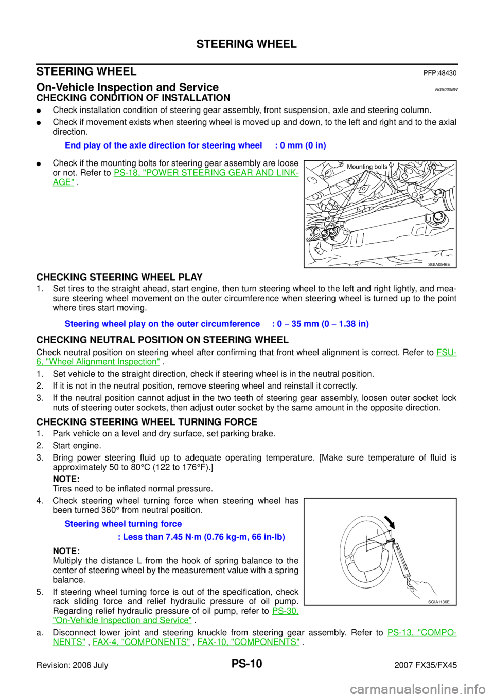
�Check if the mounting bolts for steering gear assembly are loose
or not. Refer to PS-18, "
POWER STEERING GEAR AND LINK-
AGE" .
CHECKING STEERING WHEEL PLAY
1. Set tires to the straight ahead, start engine, then turn steering wheel to the left and right lightly, and mea-
sure steering wheel movement on the outer circumference when steering wheel is turned up to the point
where tires start moving.
CHECKING NEUTRAL POSITION ON STEERING WHEEL
Check neutral position on steering wheel after confirming that front wheel alignment is correct. Refer to FSU-
6, "Wheel Alignment Inspection" .
1. Set vehicle to the straight direction, check if steering wheel is in the neutral position.
2. If it is not in the neutral position, remove steering wheel and reinstall it correctly.
3. If the neutral position cannot adjust in the two teeth of steering gear assembly, loosen outer socket lock nuts of steering outer sockets, then adjust outer socket by the same amount in the opposite direction.
CHECKING STEERING WHEEL TURNING FORCE
1. Park vehicle on a level and dry surface, set parking brake.
2. Start engine.
3. Bring power steering fluid up to adequate operating temperature. [Make sure temperature of fluid is approximately 50 to 80 °C (122 to 176 °F).]
NOTE:
Tires need to be inflated normal pressure.
4. Check steering wheel turning force when steering wheel has been turned 360 ° from neutral position.
NOTE:
Multiply the distance L from the hook of spring balance to the
center of steering wheel by the measurement value with a spring
balance.
5. If steering wheel turning force is out of the specification, check rack sliding force and relief hydraulic pressure of oil pump.
Regarding relief hydraulic pressure of oil pump, refer to PS-30,
"On-Vehicle Inspection and Service" .
a. Disconnect lower joint and steering knuckle from steering gear assembly. Refer to PS-13, "
COMPO-
NENTS" , FAX-4, "COMPONENTS" , FA X - 1 0 , "COMPONENTS" .
End play of the axle direction for steering wheel : 0 mm (0 in)
SGIA0546E
Steering wheel play on the outer circumference : 0
− 35 mm (0 − 1.38 in)
Steering wheel turning force : Less than 7.45 N·m (0.76 kg-m, 66 in-lb)
SGIA1136E