Page 2847 of 4366
![INFINITI FX35 2007 Service Manual FRONT TIMING CHAIN CASE EM-55
[VQ35DE]
C
D E
F
G H
I
J
K L
M A
EM
Revision: 2006 July 2007 FX35/FX45
16. Remove collared O-ring from front timing chain case (left and
right side).
17. R](/manual-img/42/57018/w960_57018-2846.png "INFINITI FX35 2007 Service Manual FRONT TIMING CHAIN CASE EM-55
[VQ35DE]
C
D E
F
G H
I
J
K L
M A
EM
Revision: 2006 July 2007 FX35/FX45
16. Remove collared O-ring from front timing chain case (left and
right side).
17. R")
FRONT TIMING CHAIN CASE EM-55
[VQ35DE]
C
D E
F
G H
I
J
K L
M A
EM
Revision: 2006 July 2007 FX35/FX45
16. Remove collared O-ring from front timing chain case (left and
right side).
17. Remove rocker covers (right and left banks). Refer to EM-51, "
ROCKER COVER" .
NOTE:
When only timing chain (primary) is removed, rocker cover does not need to be removed.
18. Obtain No. 1 cylinder at TDC of its compression stroke as follows:
NOTE:
When timing chain is not removed/installed, this step is not required.
a. Rotate crankshaft pulley clockwise to align timing mark (grooved line without color) with timing indicator.
b. Make sure that intake and exhaust cam noses on No. 1 cylinder (engine front side of right bank) are located as shown in the fig-
ure.
�If not, turn crankshaft one revolution (360 degrees) and align
as shown in the figure.
NOTE:
When only timing chain (primary) is removed, rocker cover does
not need to be removed. To make sure that No. 1 cylinder is at
its compression TDC, remove front timing chain case first. Then
check mating marks on camshaft sprockets. Refer to EM-72,
"INSTALLATION" .
19. Remove crankshaft pulley as follows:
a. Remove rear cover plate (2WD) or starter motor (AWD) and set ring gear stopper (SST). Refer to EM-30,
"OIL PAN AND OIL STRAINER" (2WD) or SC-11, "STARTING SYSTEM" (AWD).
b. Loosen crankshaft pulley bolt and locate bolt seating surface as 10 mm (0.39 in) from its original position.
CAUTION:
Do not remove crankshaft pulley bolt as it will be used as a
supporting point for suitable puller.
PBIC2631E
KBIA1717J
SEM418G
PBIC1103E
Page 2848 of 4366
![INFINITI FX35 2007 Service Manual EM-56
[VQ35DE]
FRONT TIMING CHAIN CASE
Revision: 2006 July 2007 FX35/FX45
c. Place suitable puller tab on holes of crankshaft pulley, and pull
crankshaft pulley through.
CAUTION:
Do not put suitabl](/manual-img/42/57018/w960_57018-2847.png "INFINITI FX35 2007 Service Manual EM-56
[VQ35DE]
FRONT TIMING CHAIN CASE
Revision: 2006 July 2007 FX35/FX45
c. Place suitable puller tab on holes of crankshaft pulley, and pull
crankshaft pulley through.
CAUTION:
Do not put suitabl")
EM-56
[VQ35DE]
FRONT TIMING CHAIN CASE
Revision: 2006 July 2007 FX35/FX45
c. Place suitable puller tab on holes of crankshaft pulley, and pull
crankshaft pulley through.
CAUTION:
Do not put suitable puller tab on crankshaft pulley periph-
ery, as this will damage internal damper.
20. Remove oil pan (lower). Refer to EM-30, "
OIL PAN AND OIL STRAINER" .
21. Loosen two mounting bolts in front of oil pan (upper) with power tool in reverse order shown in figure.
22. Remove front timing chain case as follows:
a. Loosen mounting bolts with power tool in reverse order as shown in the figure.
b. Insert suitable tool into the notch at the top of front timing chain case as shown (1).
c. Pry off case by moving a tool as shown (2).
�U s e t h e s e a l c u t t e r [ S S T: K V 1 0 1111 0 0 ( J 3 7 2 2 8 ) ] t o c u t l i q u i d
gasket for removal.
CAUTION:
�Do not use a screwdrivers or something similar.
�After removal, handle front timing chain case carefully
so it does not tilt, cant, or warp under a load.
EMQ0477D
PBIC1116E
KBIA1303E
SEM156F
Page 2849 of 4366
![INFINITI FX35 2007 Service Manual FRONT TIMING CHAIN CASE EM-57
[VQ35DE]
C
D E
F
G H
I
J
K L
M A
EM
Revision: 2006 July 2007 FX35/FX45
23. Remove O-rings from rear timing chain case.
24. Remove oil pan gasket (front). Re](/manual-img/42/57018/w960_57018-2848.png "INFINITI FX35 2007 Service Manual FRONT TIMING CHAIN CASE EM-57
[VQ35DE]
C
D E
F
G H
I
J
K L
M A
EM
Revision: 2006 July 2007 FX35/FX45
23. Remove O-rings from rear timing chain case.
24. Remove oil pan gasket (front). Re")
FRONT TIMING CHAIN CASE EM-57
[VQ35DE]
C
D E
F
G H
I
J
K L
M A
EM
Revision: 2006 July 2007 FX35/FX45
23. Remove O-rings from rear timing chain case.
24. Remove oil pan gasket (front). Refer to EM-30, "
OIL PAN AND OIL STRAINER" .
25. Remove water pump cover and chain tensioner cover from front timing chain case, if necessary.
�U s e t h e s e a l c u t t e r [ S S T: K V 1 0 1111 0 0 ( J 3 7 2 2 8 ) ] t o c u t l i q u i d g a s k e t f o r r e m o v a l .
26. Remove front oil seal from front timing chain case using a suit- able tool.
�Use a screwdriver for removal.
CAUTION:
Exercise care not to damage front timing chain case.
27. Remove timing chain and related parts. Refer to EM-64, "
TIMING CHAIN" .
28. Use a scraper to remove all traces of old liquid gasket from front and rear timing chain cases and oil pan (upper), and liquid gas-
ket mating surfaces.
CAUTION:
Be careful not to allow gasket fragments to enter oil pan.
�Remove old liquid gasket from bolt hole and thread.
PBIC2548E
EMQ0032D
SEM737G
PBIC2084E
Page 2850 of 4366
EM-58
[VQ35DE]
FRONT TIMING CHAIN CASE
Revision: 2006 July 2007 FX35/FX45
29. Use a scraper to remove all traces of liquid gasket from water
pump cover, chain tensioner cover and intake valve timing con-
trol covers.
INSTALLATION
1. Install timing chain and related parts. Refer to EM-64, "TIMING CHAIN" .
2. Hammer dowel pins (right and left) into front timing chain case up to a point close to taper in order to shorten protrusion length.
3. Install front oil seal on front timing chain case.
�Apply new engine oil to the oil seal lip and dust seal lip.
�Install it so that each seal lip is oriented as shown in the fig-
ure.
�Using a suitable drift [outer diameter: 60 mm (2.36 in)], press-
fit oil seal until it becomes flush with front timing chain case
end face.
�Make sure the garter spring is in position and seal lip is not
inverted.
4. Install water pump cover and chain tensioner cover to front timing chain case.
SEM926E
PBIC1101E
SEM715A
PBIC0790E
Page 2851 of 4366
FRONT TIMING CHAIN CASE EM-59
[VQ35DE]
C
D E
F
G H
I
J
K L
M A
EM
Revision: 2006 July 2007 FX35/FX45
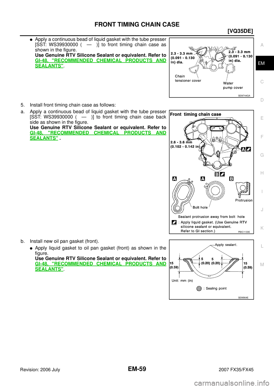
�Apply a continuous bead of liquid gasket with the tube presser
[SST: WS39930000 ( — )] to front timing chain case as
shown in the figure.
Use Genuine RTV Silicone Sealant or equivalent. Refer to
GI-48, "
RECOMMENDED CHEMICAL PRODUCTS AND
SEALANTS".
5. Install front timing chain case as follows:
a. Apply a continuous bead of liquid gasket with the tube presser [SST: WS39930000 ( — )] to front timing chain case back
side as shown in the figure.
Use Genuine RTV Silicone Sealant or equivalent. Refer to
GI-48, "
RECOMMENDED CHEMICAL PRODUCTS AND
SEALANTS" .
b. Install new oil pan gasket (front).
�Apply liquid gasket to oil pan gasket (front) as shown in the
figure.
Use Genuine RTV Silicone Sealant or equivalent. Refer to
GI-48, "
RECOMMENDED CHEMICAL PRODUCTS AND
SEALANTS".
SEM744GA
PBIC1133E
SEM964E
Page 2852 of 4366
![INFINITI FX35 2007 Service Manual EM-60
[VQ35DE]
FRONT TIMING CHAIN CASE
Revision: 2006 July 2007 FX35/FX45
�Align notch of front timing chain case with protrusion of oil pan
gasket.
�Apply liquid gasket with the tube presser [SST: W](/manual-img/42/57018/w960_57018-2851.png "INFINITI FX35 2007 Service Manual EM-60
[VQ35DE]
FRONT TIMING CHAIN CASE
Revision: 2006 July 2007 FX35/FX45
�Align notch of front timing chain case with protrusion of oil pan
gasket.
�Apply liquid gasket with the tube presser [SST: W")
EM-60
[VQ35DE]
FRONT TIMING CHAIN CASE
Revision: 2006 July 2007 FX35/FX45
�Align notch of front timing chain case with protrusion of oil pan
gasket.
�Apply liquid gasket with the tube presser [SST: WS39930000
( — )] to top surface of oil pan (upper) as shown in the fig-
ure.
Use Genuine RTV Silicone Sealant or equivalent. Refer to
GI-48, "
RECOMMENDED CHEMICAL PRODUCTS AND
SEALANTS" .
c. Install new O-rings on rear timing chain case.
d. Assemble front timing chain case as follows:
i. Fit lower end of front timing chain case tightly onto top face of oil pan (upper). From the fitting point, make entire front timing chain
case contact rear timing chain case completely.
CAUTION:
Be careful that oil pan gasket is in place.
ii. Since front timing chain case is offset for difference of bolt holes, tighten bolts temporarily with holding front timing chain case
from front and top as shown in the figure.
For bolt length and positions, refer to the step e.
iii. Same as the step ii, insert dowel pin with holding front timing chain case from front and top completely.
PBIC1114E
PBIC1099E
PBIC2548E
PBIC1100E
PBIC1115E
Page 2853 of 4366
![INFINITI FX35 2007 Service Manual FRONT TIMING CHAIN CASE EM-61
[VQ35DE]
C
D E
F
G H
I
J
K L
M A
EM
Revision: 2006 July 2007 FX35/FX45
e. Tighten mounting bolts to the specified torque in numerical order
as shown in the](/manual-img/42/57018/w960_57018-2852.png "INFINITI FX35 2007 Service Manual FRONT TIMING CHAIN CASE EM-61
[VQ35DE]
C
D E
F
G H
I
J
K L
M A
EM
Revision: 2006 July 2007 FX35/FX45
e. Tighten mounting bolts to the specified torque in numerical order
as shown in the")
FRONT TIMING CHAIN CASE EM-61
[VQ35DE]
C
D E
F
G H
I
J
K L
M A
EM
Revision: 2006 July 2007 FX35/FX45
e. Tighten mounting bolts to the specified torque in numerical order
as shown in the figure.
�There are two type of mounting bolts. Refer to the following
for locating bolts.
f. After all bolts tightened, retighten them to the specified torque in numerical order as shown in the figure.
6. Install two mounting bolts in front of oil pan (upper) in numerical order as shown in figure.
7. Install oil pan (lower). Refer to EM-30, "
OIL PAN AND OIL STRAINER" .
8. Install intake valve timing control covers as follows:
a. Install new seal rings in shaft grooves.
b. Apply a continuous bead of liquid gasket with the tube presser [SST: WS39930000 ( — )] to intake valve timing control cov-
ers as shown in the figure.
Use Genuine RTV Silicone Sealant or equivalent. Refer to
GI-48, "
RECOMMENDED CHEMICAL PRODUCTS AND
SEALANTS" .
c. Install new collared O-rings in front timing chain case oil hole (left and right sides).
d. Being careful not to move seal ring from the installation groove, align dowel pins on front timing chain case with the holes to install intake valve timing control covers. M8 bolts : 1, 2
: 28.4 N·m (2.9 kg-m, 21 ft-lb)
M6 bolts : Except the above
: 12.7 N·m (1.3 kg-m, 9 ft-lb)
: 17.2 N·m (1.8 kg-m, 13 ft-lb)
KBIA1303E
PBIC1116E
SBIA0492E
PBIC2631E
Page 2854 of 4366
![INFINITI FX35 2007 Service Manual EM-62
[VQ35DE]
FRONT TIMING CHAIN CASE
Revision: 2006 July 2007 FX35/FX45
e. Tighten mounting bolts in numerical order as shown in the fig-
ure.
9. Install crankshaft pulley as follows:
a. Fix cran](/manual-img/42/57018/w960_57018-2853.png "INFINITI FX35 2007 Service Manual EM-62
[VQ35DE]
FRONT TIMING CHAIN CASE
Revision: 2006 July 2007 FX35/FX45
e. Tighten mounting bolts in numerical order as shown in the fig-
ure.
9. Install crankshaft pulley as follows:
a. Fix cran")
EM-62
[VQ35DE]
FRONT TIMING CHAIN CASE
Revision: 2006 July 2007 FX35/FX45
e. Tighten mounting bolts in numerical order as shown in the fig-
ure.
9. Install crankshaft pulley as follows:
a. Fix crankshaft using the ring gear stopper [SST: KV10117700 (J44716)].
b. Install crankshaft pulley, taking care not to damage front oil seal.
�When press-fitting crankshaft pulley with plastic hammer, tap on its center portion (not circumference).
c. Tighten crankshaft pulley bolt.
d. Put a paint mark on crankshaft pulley aligning with angle mark on crankshaft pulley bolt.
e. Further tighten by 90 degrees. (Angle tightening)
�Check the tightening angle by referencing to the notches. The
angle between two notches is 90 degrees.
10. Rotate crankshaft pulley in normal direction (clockwise when viewed from front) to confirm it turns smoothly.
11. For the following operations, perform steps in the reverse order of removal. NOTE:
If hydraulic pressure inside chain tensioner drops after removal/installation, slack in the guide may gener-
ate a pounding noise during and just after engine start. However, this is normal. Noise will stop after
hydraulic pressure rises.
INSPECTION AFTER INSTALLATION
Inspection for Leaks
The followings are procedures for checking fluids leak, lubricates leak.
�Before starting engine, check oil/fluid levels including engine coolant and engine oil. If less than required
quantity, fill to the specified level. Refer to GI-48, "
RECOMMENDED CHEMICAL PRODUCTS AND
SEALANTS" .
�Use procedure below to check for fuel leakage.
–Turn ignition switch “ON” (with engine stopped). With fuel pressure applied to fuel piping, check for fuel
leakage at connection points.
–Start engine. With engine speed increased, check again for fuel leakage at connection points.
�Run engine to check for unusual noise and vibration.
NOTE:
If hydraulic pressure inside chain tensioner drops after removal/installation, slack in guide may generate a
pounding noise during and just after the engine start. However, this does not indicate an unusualness.
Noise will stop after hydraulic pressure rises.
PBIC0918E
: 44.1 N·m (4.5 kg-m, 33 ft-lb)
PBIC4821E
![INFINITI FX35 2007 Service Manual EM-58
[VQ35DE]
FRONT TIMING CHAIN CASE
Revision: 2006 July 2007 FX35/FX45
29. Use a scraper to remove all traces of liquid gasket from water
pump cover, chain tensioner cover and intake valve timing](/manual-img/42/57018/w960_57018-2849.png "INFINITI FX35 2007 Service Manual EM-58
[VQ35DE]
FRONT TIMING CHAIN CASE
Revision: 2006 July 2007 FX35/FX45
29. Use a scraper to remove all traces of liquid gasket from water
pump cover, chain tensioner cover and intake valve timing")