Page 3100 of 4366
![INFINITI FX35 2007 Service Manual FAX-14
[AWD]
FRONT DRIVE SHAFT
Revision: 2006 July 2007 FX35/FX45
CAUTION:
�If the boot mounting length is outside the standard, it may cause breakage in the boot.
�Be careful not to touch the inside](/manual-img/42/57018/w960_57018-3099.png "INFINITI FX35 2007 Service Manual FAX-14
[AWD]
FRONT DRIVE SHAFT
Revision: 2006 July 2007 FX35/FX45
CAUTION:
�If the boot mounting length is outside the standard, it may cause breakage in the boot.
�Be careful not to touch the inside")
FAX-14
[AWD]
FRONT DRIVE SHAFT
Revision: 2006 July 2007 FX35/FX45
CAUTION:
�If the boot mounting length is outside the standard, it may cause breakage in the boot.
�Be careful not to touch the inside of the boot with a tip of a flat-bladed screwdriver.
22. Secure the large and small ends of the boot with new boot bands using the boot band crimping tool [SST: KV40107300
( – )] as shown in the figure.
NOTE:
Secure boot band so that dimension “M” meets the specification
as shown.
23. Secure joint sub-assembly and shaft, and then make sure that they are in the correct position when rotating boot. Install them
with new boot band when boot installation positions become
incorrect.
24. Insert drive shaft to wheel hub and bearing assembly, and then temporarily tighten hub lock nut.
25. Install nuts and bolts to steering knuckle and strut.
26. Install break hose bracket to strut assembly. BR-11, "
Removal and Installation of Front Brake Tube and
Brake Hose" .
27. Install wheel sensor to strut assembly. Refer to BRC-57, "
WHEEL SENSORS" .
28. Tighten the hub lock nut to the specified torque.
29. Install cotter pin.
30. Install tires to vehicle. Boot installation length (L) : 136 mm (5.35 in)
RAC1133D
Dimension “M” : 2.0 – 3.0 mm (0.079 – 0.118 in)
DSF0047D
Page 3103 of 4366
FRONT DRIVE SHAFT FAX-17
[AWD]
C E F
G H
I
J
K L
M A
B
FA X
Revision: 2006 July 2007 FX35/FX45
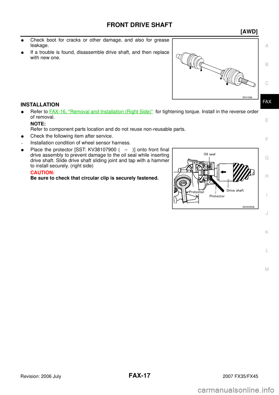
�Check boot for cracks or other damage, and also for grease
leakage.
�If a trouble is found, disassemble drive shaft, and then replace
with new one.
INSTALLATION
�Refer to FAX-16, "Removal and Installation (Right Side)" for tightening torque. Install in the reverse order
of removal.
NOTE:
Refer to component parts location and do not reuse non-reusable parts.
�Check the following item after service.
–Installation condition of wheel sensor harness.
�Place the protector [SST: KV38107900 ( – )] onto front final
drive assembly to prevent damage to the oil seal while inserting
drive shaft. Slide drive shaft sliding joint and tap with a hammer
to install securely. (right side)
CAUTION:
Be sure to check that circular clip is securely fastened.
SFA108A
SDIA0593E
Page 3106 of 4366
FAX-20
[AWD]
FRONT DRIVE SHAFT
Revision: 2006 July 2007 FX35/FX45
ASSEMBLY
Front Final Drive Assembly Side
1. If plug has been removed, use a drift (SST) to press in a new one.
NOTE:
Discard old plug; replace with new ones.
2. Wind serrated part of shaft with tape. Install boot band and boot to shaft. Be careful not to damage boot.
NOTE:
Discard old boot band and boot; replace with each new one.
3. Remove protective tape wound around serrated part of shaft.
4. Line up alignment marks which were made when spider assem- bly was removed. Install spider assembly, with serration chamfer
facing shaft.
5. Secure spider assembly with snap ring. NOTE:
Discard old snap ring; replace with new one.
6. Apply Nissan genuine grease or equivalent to spider assembly and sliding surface.
SDIA1153E
SFA800
SDIA1792E
SFA023A
Page 3107 of 4366
![INFINITI FX35 2007 Service Manual FRONT DRIVE SHAFT FAX-21
[AWD]
C E F
G H
I
J
K L
M A
B
FA X
Revision: 2006 July 2007 FX35/FX45
7. Install housing to spider assembly. Apply Nissan genuine grease
or equivalent to housing.](/manual-img/42/57018/w960_57018-3106.png "INFINITI FX35 2007 Service Manual FRONT DRIVE SHAFT FAX-21
[AWD]
C E F
G H
I
J
K L
M A
B
FA X
Revision: 2006 July 2007 FX35/FX45
7. Install housing to spider assembly. Apply Nissan genuine grease
or equivalent to housing.")
FRONT DRIVE SHAFT FAX-21
[AWD]
C E F
G H
I
J
K L
M A
B
FA X
Revision: 2006 July 2007 FX35/FX45
7. Install housing to spider assembly. Apply Nissan genuine grease
or equivalent to housing.
8. Install boot securely into grooves (indicated by *marks) shown in the figure.
CAUTION:
If there is grease on boot mounting surfaces (indicated by *
marks) of shaft and housing, boot may come off. Remove
all grease from surfaces.
9. Make sure boot installation length “L
1 L2 ” is the length indicated
below. Insert a flat-bladed screwdriver or similar tool into smaller
side of boot. Bleed air from boot to prevent boot deformation.
CAUTION:
�Boot may break if boot installation length is less than standard value.
�Take care not to touch the tip of screwdriver to inside surface of boot.
10. Install new larger and smaller boot bands securely. NOTE:
Discard old boot bands; replace with new ones.
11. After installing housing and shaft, rotate boot to check whether or not the actual position is correct. If boot position is not correct,
secure boot with new boot bands again.
12. Install circular clip. NOTE:
Discard old circular clip; replace with new one.
Wheel Side
Assemble in steps 14 to 23 of FA X - 1 2 , "DRIVE SHAFT BOOT REPLACEMENT" .
Grease amount : 95
− 105 g (3.35 − 3.70 oz)
SDIA1445E
Boot installation Length “L1 L2 ”:
VQ45DE models (L
1 ): 95 − 97 mm (3.74 − 3.82 in)
VK35DE models (L
2 ) : 150.9 − 152.9 mm (5.94 − 6.02 in)
PDIA1255E
SFA395
Page 3110 of 4366
FAX-24
[AWD]
FRONT DRIVE SHAFT
Revision: 2006 July 2007 FX35/FX45
ASSEMBLY
Front Final Drive Assembly Side
1. Wind serrated part of drive shaft with tape. Install boot band and boot to shaft. Be careful not to damage boot.
NOTE:
Discard old boot band and boot; replace with each new one.
2. Remove protective tape wound around serrated part of shaft.
3. Line up alignment marks which were made when spider assem- bly was removed. Install spider assembly, with serration chamfer
facing dive shaft.
4. Secure spider assembly with snap ring. NOTE:
Discard old snap ring; replace with new one.
5. Apply Nissan genuine grease or equivalent to spider assembly and sliding surface.
6. Install housing to spider assembly. Apply Nissan genuine grease or equivalent to housing.
SFA800
SDIA1735E
SFA023A
Grease amount : 113 − 123 g (3.99 − 4.34 oz)
SDIA1446E
Page 3111 of 4366
![INFINITI FX35 2007 Service Manual FRONT DRIVE SHAFT FAX-25
[AWD]
C E F
G H
I
J
K L
M A
B
FA X
Revision: 2006 July 2007 FX35/FX45
7. Install boot securely into grooves (indicated by * marks) shown
in the figure.
CAUTION:](/manual-img/42/57018/w960_57018-3110.png "INFINITI FX35 2007 Service Manual FRONT DRIVE SHAFT FAX-25
[AWD]
C E F
G H
I
J
K L
M A
B
FA X
Revision: 2006 July 2007 FX35/FX45
7. Install boot securely into grooves (indicated by * marks) shown
in the figure.
CAUTION:")
FRONT DRIVE SHAFT FAX-25
[AWD]
C E F
G H
I
J
K L
M A
B
FA X
Revision: 2006 July 2007 FX35/FX45
7. Install boot securely into grooves (indicated by * marks) shown
in the figure.
CAUTION:
If there is grease on boot mounting surfaces (indicated by*
marks) of shaft and housing, boot may come off. Remove
all grease from surfaces.
8. Make sure boot installation length “L” is the length indicated below. Insert a flat-bladed screwdriver or similar tool into smaller
side of boot. Bleed air from boot to prevent boot deformation.
CAUTION:
�Boot may break if boot installation length is less than standard value.
�Take care not to touch the tip of screwdriver to inside surface of boot.
9. Install new larger and smaller boot bands securely.
NOTE:
Discard old boot bands; replace with new ones.
10. Put boot band in the groove on drive shaft boot. Then fit pawls ( ) into holes to temporary installation.
NOTE:
For the large diameter side, fit projection (A) and guide slit (B) at
first.
11. Pinch projection on the band with suitable pliers to tighten band.
12. Insert tip of band below end of the pawl.
13. After installing housing and shaft, rotate boot to check whether or not the actual position is correct. If boot position is not correct,
secure boot with new boot bands again.
14. Install circular clip. NOTE:
Discard old circular clip; replace with new one.
Wheel Side
Assemble in steps 14 to 23 of FAX-12, "DRIVE SHAFT BOOT REPLACEMENT" .
Boot installation Length “L ”:
157.8 − 159.8 mm (6.21 − 6.29 in)
SDIA3250E
SDIA3557E
SDIA3558E
Page 3126 of 4366
,
uppe")
FFD-14
FRONT FINAL DRIVE ASSEMBLY
Revision: 2006 July 2007 FX35/FX45
�Tighten mounting bolts in the order as described below when
installing front final drive assembly: side of gear carrier (1),
upper side of gear carrier (2), part of carrier cover (3), lower part
of gear carrier (4).
CAUTION:
Align the mating faces of gear carrier and oil pan for instal-
lation.
�When installing breather hoses (1) and tube (2), refer to the fig-
ure.
CAUTION:
Make sure there are no pinched or restricted areas on the
breather hose caused by bending or winding when install-
ing it.
–Make sure the paint mark facing up ( ).
–Securely install the hose until it seats the rounded portion of the
tube ( ).
–Install breather connector as shown in the figure.
–Seat the breather tube bracket end (A) to the machined face (B)
of gear carrier boss.
�When oil leaks while removing final drive assembly, check oil
level after the installation. Refer to FFD-8, "
Changing Differential
Gear Oil" .
PDIA0839J
PDIA0790J
Angle “A”: 0 - 30°
PDIA0841J
PDIA0842E
Page 3155 of 4366

FUEL SYSTEM FL-3
C
D E
F
G H
I
J
K L
M A
FL
Revision: 2006 July 2007 FX35/FX45
FUEL SYSTEMPFP:17503
Checking Fuel LinesNBS004IG
Inspect fuel lines, fuel filler cap and fuel tank for improper attach-
ment, leaks, cracks, damage, loose connections, chafing or deterio-
ration.
If necessary, repair or replace damaged parts.
General PrecautionsNBS004IH
WARNING:
When replacing fuel line parts, be sure to observe the following.
�Put a “CAUTION: FLAMMABLE” sign in the workshop.
�Be sure to work in a well ventilated area and furnish workshop with a CO2 fire extinguisher.
�Do not smoke while servicing fuel system. Keep open flames and sparks away from the work area.
CAUTION:
�Use gasoline required by the regulations for octane number. Refer to GI-6, "Precautions for Fuel
(Unleaded Premium Gasoline Recommended)" .
�Before removing fuel line parts, carry out the following procedures:
–Put drained fuel in an explosion-proof container and put the lid on securely. Keep the container in
safe area.
–Release fuel pressure from the fuel lines. Refer to EC-85, "FUEL PRESSURE RELEASE" (VQ35DE)
or EC-747, "
FUEL PRESSURE RELEASE" (VK45DE).
–Disconnect negative battery terminal.
�Always replace O-ring and clamps with new ones.
�Do not kink or twist tubes when they are being installed.
�Do not tighten hose clamps excessively to avoid damaging hoses.
�After connecting fuel tube quick connectors, make sure
quick connectors are secure.
Ensure that connector and resin tube do not contact any
adjacent parts.
�After installing tubes, make sure there is no fuel leakage at
connections in the following steps.
–Apply fuel pressure to fuel lines with turning ignition switch
“ON” (with engine stopped). Then check for fuel leaks at
connections.
–Start engine and rev it up and check for fuel leaks at con-
nections.
�Use only a genuine NISSAN fuel filler cap as a replacement.
If an incorrect fuel filler cap is used, the “MIL” may come
on.
�For servicing “Evaporative Emission System” parts, refer to
EC-38, "
EVAPORATIVE EMISSION SYSTEM" (VQ35DE) or
EC-700, "
EVAPORATIVE EMISSION SYSTEM" (VK45DE).
�For servicing“On Board Refueling Vapor Recovery (ORVR)”
parts, refer to EC-45, "
ON BOARD REFUELING VAPOR
RECOVERY (ORVR)" (VQ35DE) or EC-707, "ON BOARD
REFUELING VAPOR RECOVERY (ORVR)" (VK45DE).
SMA803A
SBIA0504E
![INFINITI FX35 2007 Service Manual FAX-20
[AWD]
FRONT DRIVE SHAFT
Revision: 2006 July 2007 FX35/FX45
ASSEMBLY
Front Final Drive Assembly Side
1. If plug has been removed, use a drift (SST) to press in a new one.
NOTE:
Discard old p](/manual-img/42/57018/w960_57018-3105.png "INFINITI FX35 2007 Service Manual FAX-20
[AWD]
FRONT DRIVE SHAFT
Revision: 2006 July 2007 FX35/FX45
ASSEMBLY
Front Final Drive Assembly Side
1. If plug has been removed, use a drift (SST) to press in a new one.
NOTE:
Discard old p")
![INFINITI FX35 2007 Service Manual FAX-24
[AWD]
FRONT DRIVE SHAFT
Revision: 2006 July 2007 FX35/FX45
ASSEMBLY
Front Final Drive Assembly Side
1. Wind serrated part of drive shaft with tape. Install boot band and boot to shaft. Be car](/manual-img/42/57018/w960_57018-3109.png "INFINITI FX35 2007 Service Manual FAX-24
[AWD]
FRONT DRIVE SHAFT
Revision: 2006 July 2007 FX35/FX45
ASSEMBLY
Front Final Drive Assembly Side
1. Wind serrated part of drive shaft with tape. Install boot band and boot to shaft. Be car")