Page 3038 of 4366
![INFINITI FX35 2007 Service Manual EM-246
[VK45DE]
ENGINE ASSEMBLY
Revision: 2006 July 2007 FX35/FX45
Separation Work
1. Change engine slinger installing to cylinder head (right bank).
NOTE:
In order to keep secure position when hois](/manual-img/42/57018/w960_57018-3037.png "INFINITI FX35 2007 Service Manual EM-246
[VK45DE]
ENGINE ASSEMBLY
Revision: 2006 July 2007 FX35/FX45
Separation Work
1. Change engine slinger installing to cylinder head (right bank).
NOTE:
In order to keep secure position when hois")
EM-246
[VK45DE]
ENGINE ASSEMBLY
Revision: 2006 July 2007 FX35/FX45
Separation Work
1. Change engine slinger installing to cylinder head (right bank).
NOTE:
In order to keep secure position when hoisting engine.
2. Remove engine mounting insulators (RH and LH) under side nut with power tool.
3. Lift with hoist and separate engine and transmission assembly from front suspension member. CAUTION:
�Before and during this lifting, always make sure that any harnesses are left connected.
�Avoid damage to and oil/grease smearing or spills onto engine mounting insulator.
4. Remove alternator. Refer to SC-24, "
CHARGING SYSTEM" .
5. Remove starter motor. Refer to SC-11, "
STARTING SYSTEM" .
6. Separate engine from transmission assembly. Refer to AT- 2 6 9 , "
Removal and Installation (AWD Models)"
.
7. Remove front final drive from engine. Refer to FFD-13, "
FRONT FINAL DRIVE ASSEMBLY" .
8. Remove engine mounting insulators (RH and LH) and brackets (RH and LH) from engine with power tool.
9. Remove engine rear member and engine mounting insulator (rear) from transmission.
INSTALLATION
Note the following, and install in the reverse order of removal.
�Do not allow engine mounting insulator to be damage and careful no engine oil gets on it.
�For a location with a positioning pin, insert it securely into hole of mating part.
�For a part with a specified installation orientation, refer to component figure in EM-243, "Removal and
Installation" .
�When installing engine mounting brackets (RH and LH) on cylin-
der block, tighten two upper bolts (shown as “A” in the figure)
first. Then tighten two lower bolts (shown as “B” in the figure).
INSPECTION AFTER INSTALLATION
Inspection for Leaks
The followings are procedures for checking fluids leak, lubricates leak and exhaust gases leak.
�Before starting engine, check oil/fluid levels including engine coolant and engine oil. If less than required
quantity, fill to the specified level. Refer to MA-12, "
RECOMMENDED FLUIDS AND LUBRICANTS" .
�Use procedure below to check for fuel leakage.
–Turn ignition switch “ON” (with engine stopped). With fuel pressure applied to fuel piping, check for fuel
leakage at connection points.
–Start engine. With engine speed increased, check again for fuel leakage at connection points.
�Run engine to check for unusual noise and vibration.
�Warm up engine thoroughly to make sure there is no leakage of fuel, exhaust gases, or any oil/fluids
including engine oil and engine coolant. Slinger bolts:
: 33.4 N·m (3.4 kg-m, 25 ft-lb)
PBIC2447E
PBIC2365E
Page 3041 of 4366
![INFINITI FX35 2007 Service Manual CYLINDER BLOCK EM-249
[VK45DE]
C
D E
F
G H
I
J
K L
M A
EM
Revision: 2006 July 2007 FX35/FX45
�Refer to GI-11, "Components" for symbol marks in the figure.
Disassembly and AssemblyNBS003I](/manual-img/42/57018/w960_57018-3040.png "INFINITI FX35 2007 Service Manual CYLINDER BLOCK EM-249
[VK45DE]
C
D E
F
G H
I
J
K L
M A
EM
Revision: 2006 July 2007 FX35/FX45
�Refer to GI-11, \"Components\" for symbol marks in the figure.
Disassembly and AssemblyNBS003I")
CYLINDER BLOCK EM-249
[VK45DE]
C
D E
F
G H
I
J
K L
M A
EM
Revision: 2006 July 2007 FX35/FX45
�Refer to GI-11, "Components" for symbol marks in the figure.
Disassembly and AssemblyNBS003IR
DISASSEMBLY
NOTE:
Explained here is how to disassemble with engine stand supporting transmission surface. When using differ-
ent type of engine stand, note with difference in steps and etc.
1. Remove engine assembly from vehicle, and separate front suspension member, transmission and front final drive from engine. Refer to EM-243, "
ENGINE ASSEMBLY" .
2. Remove the parts that may restrict installation of engine to widely use engine stand.
NOTE:
The procedure is described assuming that you use widely use engine holding the surface, to which trans-
mission is installed.
a. Remove drive plate.
�Holding ring gear with ring gear stopper (SST).
�Loosen mounting bolts diagonally order.
CAUTION:
�Do not disassemble drive plate.
�Do not place drive plate with signal plate facing down.
�When handling signal plate, take care not to damage or
scratch it.
�Handle signal plate in a manner that prevents it from
becoming magnetized.
b. Remove engine rear plate.
3. Lift engine with hoist to install it onto widely use engine stand. CAUTION:
Use engine stand that has a load capacity [approximately 240 kg (529 lb) or more] large enough for
supporting the engine weight.
�If the load capacity of stand is not adequate, remove the following parts beforehand to reduce the
potential risk of overturning stand.
13. Piston pin 14. Connecting rod bearing 15. Connecting rod bearing cap
16. Block heater protector 17. Connector cap 18. Cylinder block heater
19. Gasket 20. Main bearing cap 21. Thrust bearing
22. Main bearing 23. Rear plate 24. Crankshaft
25. Pilot converter 26. Drive plate 27. Thrust bearing
28. Side bolt 29. Reinforcement plate 30. Crankshaft position sensor (POS)
31. O-ring 32. Rear oil seal 33. Rear oil seal retainer
A. Refererence: Installed on transmis-
sion B. Refer to
EM-253
C. Right bank
D. Cylinder block heater (For Canada) E. Chamfered F. Crankshaft side : Engine front
PBIC1656E
PBIC2367E
Page 3101 of 4366
![INFINITI FX35 2007 Service Manual FRONT DRIVE SHAFT FAX-15
[AWD]
C E F
G H
I
J
K L
M A
B
FA X
Revision: 2006 July 2007 FX35/FX45
Removal and Installation (Left Side)NDS000C6
COMPONENTS
REMOVAL
1. Remove tires from vehicle](/manual-img/42/57018/w960_57018-3100.png "INFINITI FX35 2007 Service Manual FRONT DRIVE SHAFT FAX-15
[AWD]
C E F
G H
I
J
K L
M A
B
FA X
Revision: 2006 July 2007 FX35/FX45
Removal and Installation (Left Side)NDS000C6
COMPONENTS
REMOVAL
1. Remove tires from vehicle")
FRONT DRIVE SHAFT FAX-15
[AWD]
C E F
G H
I
J
K L
M A
B
FA X
Revision: 2006 July 2007 FX35/FX45
Removal and Installation (Left Side)NDS000C6
COMPONENTS
REMOVAL
1. Remove tires from vehicle with power tool.
2. Remove undercover with power tool.
3. Remove cotter pin. Then remove lock nut from drive shaft with power tool.
4. Remove wheel sensor harness from strut assembly. Refer to BRC-57, "
WHEEL SENSORS" .
CAUTION:
Do not pull on wheel sensor harness.
5. Remove brake hose lock plate. Then remove brake hose from strut assembly. Refer to BR-11, "
BRAKE
TUBE AND HOSE" .
6. Remove fixing bolts and nuts between strut assembly and steering knuckle with power tool.
7. Using a puller (suitable tool), remove drive shaft from steering knuckle.
CAUTION:
When removing drive shaft, do not apply an excessive
angle to drive shaft joint. Also be careful not to excessively
extend slide joint.
8. Remove fixing bolt of front final drive side assembly drive shaft with power tool, then remove drive shaft from vehicle.
INSPECTION AFTER REMOVAL
�Move joint up/down, left /right, and in the axial direction. Check for any rough movement or significant
looseness.
�Check boot for cracks or other damage, and also for grease
leakage.
�If a trouble is found, disassemble drive shaft, and then replace
with new one.
INSTALLATION
�Refer to FAX-15, "Removal and Installation (Left Side)" for tightening torque. Install in the reverse order of
removal.
1. Cotter pin 2. Washer 3. Drive shaft
Refer to GI-11, "
Components" , for the symbols in the figure.
PDIA1218E
SDIA0972J
SDIA1046J
Page 3102 of 4366
![INFINITI FX35 2007 Service Manual FAX-16
[AWD]
FRONT DRIVE SHAFT
Revision: 2006 July 2007 FX35/FX45
NOTE:
Refer to component parts location and do not reuse non-reusable parts.
�Check the following item after service.
–Installation](/manual-img/42/57018/w960_57018-3101.png "INFINITI FX35 2007 Service Manual FAX-16
[AWD]
FRONT DRIVE SHAFT
Revision: 2006 July 2007 FX35/FX45
NOTE:
Refer to component parts location and do not reuse non-reusable parts.
�Check the following item after service.
–Installation")
FAX-16
[AWD]
FRONT DRIVE SHAFT
Revision: 2006 July 2007 FX35/FX45
NOTE:
Refer to component parts location and do not reuse non-reusable parts.
�Check the following item after service.
–Installation condition of wheel sensor harness
Removal and Installation (Right Side)NDS000C7
COMPONENTS
REMOVAL
1. Remove tires from vehicle with power tool.
2. Remove undercover with power tool.
3. Remove cotter pin. Then remove lock nut from drive shaft with power tool.
4. Remove wheel sensor harness from strut assembly. Refer to BRC-57, "
WHEEL SENSORS" .
CAUTION:
Do not pull on wheel sensor harness.
5. Remove brake hose lock prate. Then remove brake hose from strut assembly. Refer to BR-11, "
BRAKE
TUBE AND HOSE" .
6. Remove fixing bolts and nuts between strut assembly and steering knuckle with power tool.
7. Using a puller (suitable tool), remove drive shaft from steering knuckle.
CAUTION:
When removing drive shaft, do not apply an excessive
angle to drive shaft joint. Also be careful not to excessively
extend slide joint.
8. Pry off drive shaft from front final drive assembly side as shown in the figure.
INSPECTION AFTER REMOVAL
�Move joint up/down, left/right, and in the axial direction. Check for any rough movement or significant
looseness.
1. Cotter pin 2. Washer 3. Drive shaft
Refer to GI-11, "
Components" , for the symbols in the figure.
PDIA1219E
SDIA0972J
SDIA1489E
Page 3103 of 4366
FRONT DRIVE SHAFT FAX-17
[AWD]
C E F
G H
I
J
K L
M A
B
FA X
Revision: 2006 July 2007 FX35/FX45
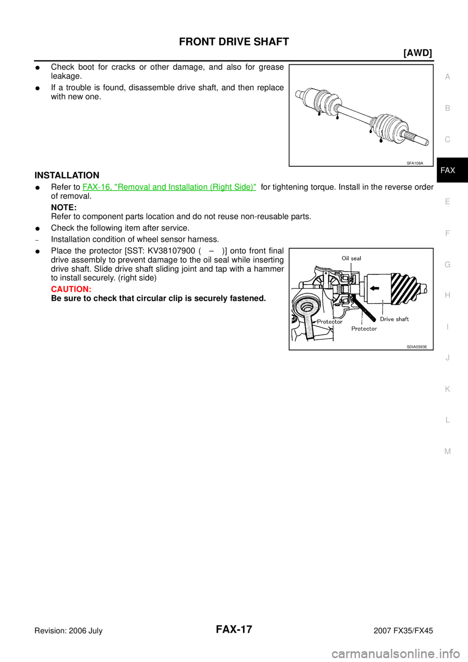
�Check boot for cracks or other damage, and also for grease
leakage.
�If a trouble is found, disassemble drive shaft, and then replace
with new one.
INSTALLATION
�Refer to FAX-16, "Removal and Installation (Right Side)" for tightening torque. Install in the reverse order
of removal.
NOTE:
Refer to component parts location and do not reuse non-reusable parts.
�Check the following item after service.
–Installation condition of wheel sensor harness.
�Place the protector [SST: KV38107900 ( – )] onto front final
drive assembly to prevent damage to the oil seal while inserting
drive shaft. Slide drive shaft sliding joint and tap with a hammer
to install securely. (right side)
CAUTION:
Be sure to check that circular clip is securely fastened.
SFA108A
SDIA0593E
Page 3104 of 4366
FAX-18
[AWD]
FRONT DRIVE SHAFT
Revision: 2006 July 2007 FX35/FX45
Disassembly and Assembly (Left Side)NDS000C8
COMPONENTS
DISASSEMBLY
Front Final Drive Assembly Side
1. Press drive shaft in a vice.
CAUTION:
When retaining shaft in a vice, always use copper or aluminum plates between vise and shaft.
2. Remove boot bands.
3. If plug needs to be removed, move boot to wheel side, and drive it out with a plastic hammer.
4. Put matching marks on spider assembly and shaft. CAUTION:
Use paint for matching mark, but don’t damage to spider
assembly and drive shaft.
1. Plug 2. Housing 3. Snap ring
4. Spider assembly 5. Boot band 6. Boot
7. Shaft 8. Circular clip 9. Joint sub-assembly
Refer to GI-11, "
Components" and the following for the symbols in the figure.
: Fill Nissan genuine grease or equivalent.
PDIA1220E
SFA963
Page 3106 of 4366
FAX-20
[AWD]
FRONT DRIVE SHAFT
Revision: 2006 July 2007 FX35/FX45
ASSEMBLY
Front Final Drive Assembly Side
1. If plug has been removed, use a drift (SST) to press in a new one.
NOTE:
Discard old plug; replace with new ones.
2. Wind serrated part of shaft with tape. Install boot band and boot to shaft. Be careful not to damage boot.
NOTE:
Discard old boot band and boot; replace with each new one.
3. Remove protective tape wound around serrated part of shaft.
4. Line up alignment marks which were made when spider assem- bly was removed. Install spider assembly, with serration chamfer
facing shaft.
5. Secure spider assembly with snap ring. NOTE:
Discard old snap ring; replace with new one.
6. Apply Nissan genuine grease or equivalent to spider assembly and sliding surface.
SDIA1153E
SFA800
SDIA1792E
SFA023A
Page 3108 of 4366
FAX-22
[AWD]
FRONT DRIVE SHAFT
Revision: 2006 July 2007 FX35/FX45
Disassembly and Assembly (Right Side)NDS000C9
COMPONENTS
DISASSEMBLY
Front Final Drive Assembly Side
1. Press drive shaft in a vice.
CAUTION:
When retaining drive shaft in a vice, always use copper or aluminum plates between a vise and
shaft.
2. Remove boot bands.
3. Put matching marks on spider assembly and shaft. CAUTION:
Use paint for matching mark, but don’t damage to spider
assembly and shaft.
1. Joint sub-assembly 2. Circular clip 3. Boot band
4. Boot 5. Shaft 6. Spider assembly
7. Snap ring 8. Housing 9. Dust shield
10. Circular clip
Refer to GI-11, "
Components" and the following for the symbols in the figure.
: Fill NiSSAN genuine grease or equivalent.
PDIA1221E
SFA963
![INFINITI FX35 2007 Service Manual FAX-18
[AWD]
FRONT DRIVE SHAFT
Revision: 2006 July 2007 FX35/FX45
Disassembly and Assembly (Left Side)NDS000C8
COMPONENTS
DISASSEMBLY
Front Final Drive Assembly Side
1. Press drive shaft in a vice.](/manual-img/42/57018/w960_57018-3103.png "INFINITI FX35 2007 Service Manual FAX-18
[AWD]
FRONT DRIVE SHAFT
Revision: 2006 July 2007 FX35/FX45
Disassembly and Assembly (Left Side)NDS000C8
COMPONENTS
DISASSEMBLY
Front Final Drive Assembly Side
1. Press drive shaft in a vice.")
![INFINITI FX35 2007 Service Manual FAX-20
[AWD]
FRONT DRIVE SHAFT
Revision: 2006 July 2007 FX35/FX45
ASSEMBLY
Front Final Drive Assembly Side
1. If plug has been removed, use a drift (SST) to press in a new one.
NOTE:
Discard old p](/manual-img/42/57018/w960_57018-3105.png "INFINITI FX35 2007 Service Manual FAX-20
[AWD]
FRONT DRIVE SHAFT
Revision: 2006 July 2007 FX35/FX45
ASSEMBLY
Front Final Drive Assembly Side
1. If plug has been removed, use a drift (SST) to press in a new one.
NOTE:
Discard old p")
![INFINITI FX35 2007 Service Manual FAX-22
[AWD]
FRONT DRIVE SHAFT
Revision: 2006 July 2007 FX35/FX45
Disassembly and Assembly (Right Side)NDS000C9
COMPONENTS
DISASSEMBLY
Front Final Drive Assembly Side
1. Press drive shaft in a vice.](/manual-img/42/57018/w960_57018-3107.png "INFINITI FX35 2007 Service Manual FAX-22
[AWD]
FRONT DRIVE SHAFT
Revision: 2006 July 2007 FX35/FX45
Disassembly and Assembly (Right Side)NDS000C9
COMPONENTS
DISASSEMBLY
Front Final Drive Assembly Side
1. Press drive shaft in a vice.")