Page 3564 of 4366
LT-108
TURN SIGNAL AND HAZARD WARNING LAMPS
Revision: 2006 July 2007 FX35/FX45
Bulb Replacement (Front Turn Signal Lamp)NKS002XQ
Refer to LT- 3 4 , "Bulb Replacement" .
Bulb Replacement (Rear Turn Signal Lamp)NKS002XR
Refer to LT- 1 5 1 , "Bulb Replacement" .
Removal and Installation of Front Turn Signal LampNKS002XS
Refer to LT- 3 5 , "Removal and Installation" .
Removal and Installation of Rear Turn Signal Lamp NKS002XT
Refer to LT- 1 5 1 , "Removal and Installation" .
Removal and Installation of Rear Combination Lamp Control UnitNKS002XU
REMOVAL
1. Remove luggage side box (LH). Refer to EI-45, "Removal and
Installation" .
2. Remove nuts (2), and remove rear combination lamp control unit.
INSTALLATION
Installation is the reverse order of removal.
PKIB3631E
Page 3584 of 4366

LT-128
STOP LAMP
Revision: 2006 July 2007 FX35/FX45
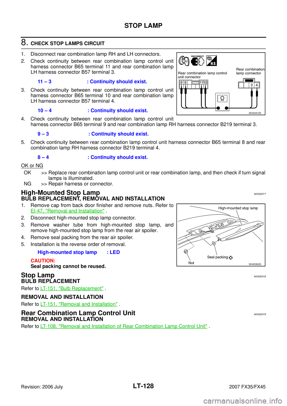
8. CHECK STOP LAMPS CIRCUIT
1. Disconnect rear combination lamp RH and LH connectors.
2. Check continuity between rear combination lamp control unit harness connector B65 terminal 11 and rear combination lamp
LH harness connector B57 terminal 3.
3. Check continuity between rear combination lamp control unit harness connector B65 terminal 10 and rear combination lamp
LH harness connector B57 terminal 4.
4. Check continuity between rear combination lamp control unit harness connector B65 terminal 9 and rear combination lamp RH harness connector B219 terminal 3.
5. Check continuity between rear combination lamp control unit harness connector B65 terminal 8 and rear combination lamp RH harness connector B219 terminal 4.
OK or NG
OK >> Replace rear combination lamp control unit or rear combination lamp, and then check if turn signal lamps is illuminated.
NG >> Repair harness or connector.
High-Mounted Stop LampNKS002Y7
BULB REPLACEMENT, REMOVAL AND INSTALLATION
1. Remove cap from back door finisher and remove nuts. Refer to EI-47, "
Removal and Installation" .
2. Disconnect high-mounted stop lamp connector.
3. Remove washer tube from high-mounted stop lamp, and remove high-mounted stop lamp from the rear air spoiler.
4. Remove seal packing from the rear air spoiler.
5. Installation is the reverse order of removal.
CAUTION:
Seal packing cannot be reused.
Stop LampNKS002Y8
BULB REPLACEMENT
Refer to LT- 1 5 1 , "Bulb Replacement" .
REMOVAL AND INSTALLATION
Refer to LT- 1 5 1 , "Removal and Installation" .
Rear Combination Lamp Control UnitNKS002Y9
REMOVAL AND INSTALLATION
Refer to LT- 1 0 8 , "Removal and Installation of Rear Combination Lamp Control Unit" .
11 – 3 : Continuity should exist.
10 – 4 : Continuity should exist.
9 – 3 : Continuity should exist.
8 – 4 : Continuity should exist.
SKIA5910E
High-mounted stop lamp : LED
SKIA5562E
Page 3603 of 4366

PARKING, LICENSE PLATE AND TAIL LAMPS LT-147
C
D E
F
G H
I
J
L
M A
B
LT
Revision: 2006 July 2007 FX35/FX45
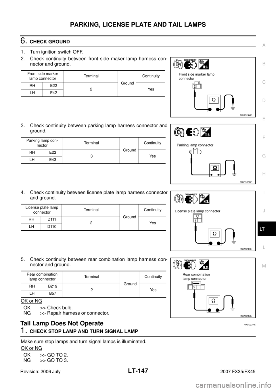
6. CHECK GROUND
1. Turn ignition switch OFF.
2. Check continuity between front side maker lamp harness con- nector and ground.
3. Check continuity between parking lamp harness connector and ground.
4. Check continuity between license plate lamp harness connector and ground.
5. Check continuity between rear combination lamp harness con- nector and ground.
OK or NG
OK >> Check bulb.
NG >> Repair harness or connector.
Tail Lamp Does Not OperateNKS003HC
1. CHECK STOP LAMP AND TURN SIGNAL LAMP
Make sure stop lamps and turn signal lamps is illuminated.
OK or NG
OK >> GO TO 2.
NG >> GO TO 3.
Front side marker
lamp connector Terminal
Ground Continuity
RH E22 2Yes
LH E42
PKIA5244E
Parking lamp con-
nector Terminal
Ground Continuity
RH E23 3Yes
LH E43
PKIC9688E
License plate lamp
connector Terminal
Ground Continuity
RH D111 2Yes
LH D110
PKIA5246E
Rear combination
lamp connector Terminal
Ground Continuity
RH B219 2Yes
LH B57
PKIA5247E
Page 3607 of 4366

REAR COMBINATION LAMP LT-151
C
D E
F
G H
I
J
L
M A
B
LT
Revision: 2006 July 2007 FX35/FX45
REAR COMBINATION LAMPPFP:26554
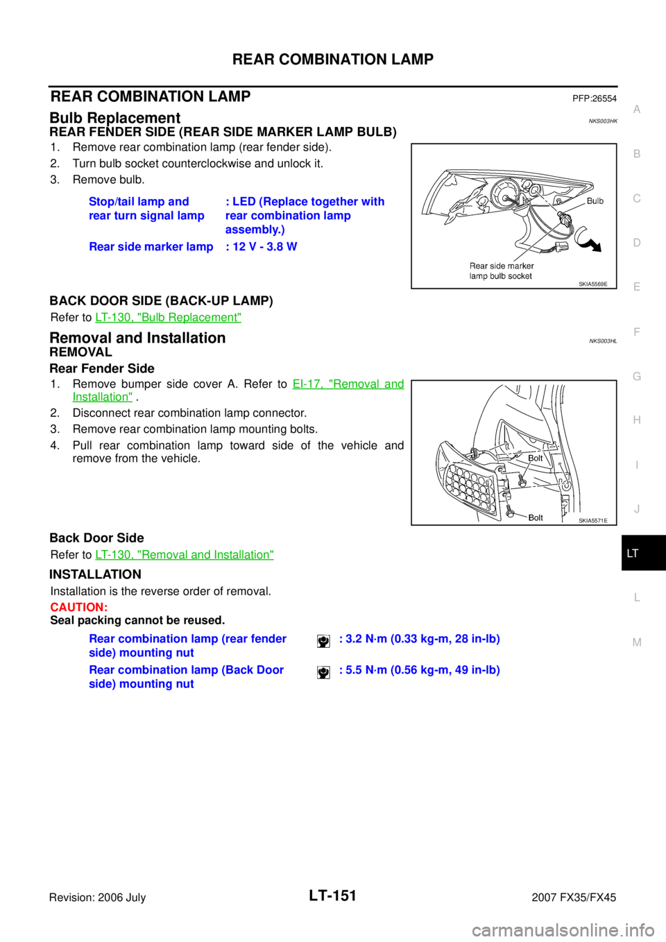
Bulb ReplacementNKS003HK
REAR FENDER SIDE (REAR SIDE MARKER LAMP BULB)
1. Remove rear combination lamp (rear fender side).
2. Turn bulb socket counterclockwise and unlock it.
3. Remove bulb.
BACK DOOR SIDE (BACK-UP LAMP)
Refer to LT- 1 3 0 , "Bulb Replacement"
Removal and InstallationNKS003HL
REMOVAL
Rear Fender Side
1. Remove bumper side cover A. Refer to EI-17, "Removal and
Installation" .
2. Disconnect rear combination lamp connector.
3. Remove rear combination lamp mounting bolts.
4. Pull rear combination lamp toward side of the vehicle and remove from the vehicle.
Back Door Side
Refer to LT- 1 3 0 , "Removal and Installation"
INSTALLATION
Installation is the reverse order of removal.
CAUTION:
Seal packing cannot be reused. Stop/tail lamp and
rear turn signal lamp : LED (Replace together with
rear combination lamp
assembly.)
Rear side marker lamp : 12 V - 3.8 W
SKIA5569E
SKIA5571E
Rear combination lamp (rear fender
side) mounting nut : 3.2 N·m (0.33 kg-m, 28 in-lb)
Rear combination lamp (Back Door
side) mounting nut : 5.5 N·m (0.56 kg-m, 49 in-lb)
Page 3657 of 4366
BULB SPECIFICATIONS LT-201
C
D E
F
G H
I
J
L
M A
B
LT
Revision: 2006 July 2007 FX35/FX45
BULB SPECIFICATIONSPFP:26297
HeadlampNKS002Z8
Exterior LampNKS002Z9
Interior Lamp/IlluminationNKS002ZA
Item Wattage (W)
High/Low (Xenon type) 35 (D2S)
Item Wattage (W)
Front combination lamp Front turn signal lamp 21 (amber)
Daytime/Parking lamp 21/5
Front side marker lamp 3.8
Rear combination lamp Stop/Tail lamp and Rear Turn signal lamp LED
Rear side marker lamp 3.8
Front fog lamp 35 (H8)
Back-up lamp 18
License plate lamp 5
High-mounted stop lamp (back door mount) LED
Item Wattage (W)
Map lamp 8
Interior room lamp 10
Personal lamp 8
Luggage room lamp 8
Step lamp 5
Glove box lamp 1.4
Vanity mirror lamp 1.32
Ignition key hole illumination 0.8
A/T device illumination lamp 1.4
Coin box illumination lamp 1.4
Page 3766 of 4366

PG-22
IPDM E/R (INTELLIGENT POWER DISTRIBUTION MODULE ENGINE ROOM)
Revision: 2006 July 2007 FX35/FX45
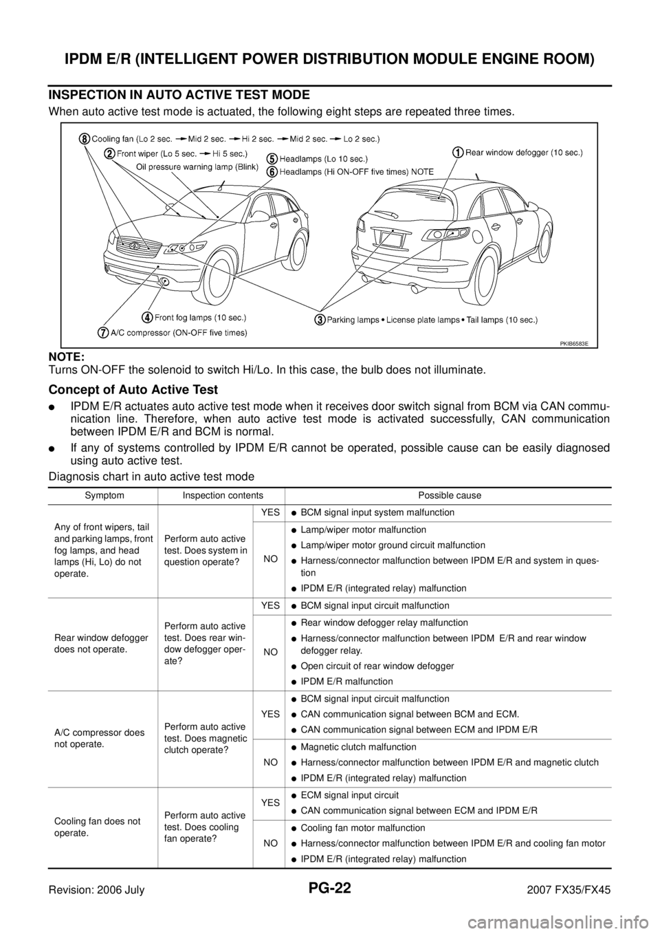
INSPECTION IN AUTO ACTIVE TEST MODE
When auto active test mode is actuated, the following eight steps are repeated three times.
NOTE:
Turns ON-OFF the solenoid to switch Hi/Lo. In this case, the bulb does not illuminate.
Concept of Auto Active Test
�IPDM E/R actuates auto active test mode when it receives door switch signal from BCM via CAN commu-
nication line. Therefore, when auto active test mode is activated successfully, CAN communication
between IPDM E/R and BCM is normal.
�If any of systems controlled by IPDM E/R cannot be operated, possible cause can be easily diagnosed
using auto active test.
Diagnosis chart in auto active test mode
PKIB6583E
Symptom Inspection contents Possible cause
Any of front wipers, tail
and parking lamps, front
fog lamps, and head
lamps (Hi, Lo) do not
operate. Perform auto active
test. Does system in
question operate? YES
�BCM signal input system malfunction
NO
�Lamp/wiper motor malfunction
�Lamp/wiper motor ground circuit malfunction
�Harness/connector malfunction between IPDM E/R and system in ques-
tion
�IPDM E/R (integrated relay) malfunction
Rear window defogger
does not operate. Perform auto active
test. Does rear win-
dow defogger oper-
ate? YES
�BCM signal input circuit malfunction
NO
�Rear window defogger relay malfunction
�Harness/connector malfunction between IPDM E/R and rear window
defogger relay.
�Open circuit of rear window defogger
�IPDM E/R malfunction
A/C compressor does
not operate. Perform auto active
test. Does magnetic
clutch operate? YES
�BCM signal input circuit malfunction
�CAN communication signal between BCM and ECM.
�CAN communication signal between ECM and IPDM E/R
NO
�Magnetic clutch malfunction
�Harness/connector malfunction between IPDM E/R and magnetic clutch
�IPDM E/R (integrated relay) malfunction
Cooling fan does not
operate. Perform auto active
test. Does cooling
fan operate? YES
�ECM signal input circuit
�CAN communication signal between ECM and IPDM E/R
NO
�Cooling fan motor malfunction
�Harness/connector malfunction between IPDM E/R and cooling fan motor
�IPDM E/R (integrated relay) malfunction