Page 2803 of 4366
PREPARATION EM-11
[VQ35DE]
C
D E
F
G H
I
J
K L
M A
EM
Revision: 2006 July 2007 FX35/FX45
(—)
TORX socket Removing and installing flywheel
Size: T55
(—)
Manual lift table caddy Removing and installing engine
(J24239-01)
Cylinder head bolt wrench Loosening and tightening cylinder head bolt,
and used with the angle wrench [SST:
KV10112100 (BT8653-A)]
a: 13 (0.51) dia.
b: 12 (0.47)
c: 10 (0.39)
Unit: mm (in)
(—)
1.Compression tester
2.Adapter Checking compression pressure
(—)
Spark plug wrench Removing and installing spark plug
(—)
Valve seat cutter set Finishing valve seat dimensions
(—)
Piston ring expander Removing and installing piston ring
(Kent-Moore No.)
Tool name Description
PBIC1113E
ZZA1210D
NT583
ZZA0008D
NT047
NT048
NT030
Page 2900 of 4366
![INFINITI FX35 2007 Service Manual EM-108
[VQ35DE]
CYLINDER HEAD
Revision: 2006 July 2007 FX35/FX45
8. Install valve collet.
�Compress valve spring with the valve spring compressor, the
attachment and the adapter (SST). Install valve](/manual-img/42/57018/w960_57018-2899.png "INFINITI FX35 2007 Service Manual EM-108
[VQ35DE]
CYLINDER HEAD
Revision: 2006 July 2007 FX35/FX45
8. Install valve collet.
�Compress valve spring with the valve spring compressor, the
attachment and the adapter (SST). Install valve")
EM-108
[VQ35DE]
CYLINDER HEAD
Revision: 2006 July 2007 FX35/FX45
8. Install valve collet.
�Compress valve spring with the valve spring compressor, the
attachment and the adapter (SST). Install valve collet with a
magnet hand.
CAUTION:
When working, take care not to damage valve lifter holes.
�Tap valve stem edge lightly with plastic hammer after installa-
tion to check its installed condition.
9. Install valve lifter.
�Install it in the original position.
10. Install spark plug tube.
�Press-fit spark plug tube as follows:
a. Remove old liquid gasket adhering to cylinder head mounting hole.
b. Apply sealant to area within approximately 12 mm (0.47 in) from edge of spark plug tube press-fit side. Use Genuine High Strength Locking Sealant or equivalent. Refer to GI-48, "
RECOMMENDED
CHEMICAL PRODUCTS AND SEALANTS" .
c. Using drift, press-fit spark plug tube so that its height “H” is as specified in the figure.
CAUTION:
�When press-fitting, take care not to deform spark plug
tube.
�After press-fitting, wipe off liquid gasket protruding onto
cylinder-head upper face.
11. Install spark plug with spark plug wrench (commercial service tool).
Inspection After DisassemblyNBS003H0
VALVE DIMENSIONS
�Check the dimensions of each valve. For the dimensions, refer to EM-155, "Valve Dimensions" .
�If dimensions are out of the standard, replace valve and check valve seat contact. Refer to EM-110,
"VALVE SEAT CONTACT" .
VALVE GUIDE CLEARANCE
Valve Stem Diameter
Measure the diameter of valve stem with micrometer.
Valve Guide Inner Diameter
Measure the inner diameter of valve guide with an inside micrometer.
PBIC1803E
Standard press-fit height “H”:
: 38.1 - 39.1 mm (1.500 - 1.539 in)
PBIC2638E
StandardIntake : 5.965 - 5.980 mm (0.2348 - 0.2354 in)
Exhaust : 5.955 - 5.970 mm (0.2344 - 0.2350 in)
SEM938C
Page 2902 of 4366
![INFINITI FX35 2007 Service Manual EM-110
[VQ35DE]
CYLINDER HEAD
Revision: 2006 July 2007 FX35/FX45
4. Heat cylinder head to 110 to 130°C (230 to 266 °F) by soaking in
heated oil.
5. Using the valve guide drift (commercial service](/manual-img/42/57018/w960_57018-2901.png "INFINITI FX35 2007 Service Manual EM-110
[VQ35DE]
CYLINDER HEAD
Revision: 2006 July 2007 FX35/FX45
4. Heat cylinder head to 110 to 130°C (230 to 266 °F) by soaking in
heated oil.
5. Using the valve guide drift (commercial service")
EM-110
[VQ35DE]
CYLINDER HEAD
Revision: 2006 July 2007 FX35/FX45
4. Heat cylinder head to 110 to 130°C (230 to 266 °F) by soaking in
heated oil.
5. Using the valve guide drift (commercial service tool), press valve guide from camshaft side to the dimensions as in the figure.
WARNING:
Cylinder head contains heat. When working, wear protec-
tive equipment to avoid getting burned.
6. Using the valve guide reamer (commercial service tool), apply reamer finish to valve guide.
VALVE SEAT CONTACT
�After confirming that the dimensions of valve guides and valves
are within the specifications, perform this procedure.
�Apply prussian blue (or white lead) onto contacting surface of
valve seat to check the condition of the valve contact on the sur-
face.
�Check if the contact area band is continuous all around the cir-
cumference.
�If not, grind to adjust valve fitting and check again. If the contact-
ing surface still has “NG” conditions even after the re-check,
replace valve seat. Refer to EM-110, "
VALVE SEAT REPLACE-
MENT" .
VALVE SEAT REPLACEMENT
When valve seat is removed, replace with oversized [0.5 mm (0.020 in)] valve seat.
1. Bore out old seat until it collapses. Boring should not continue beyond the bottom face of the seat recess in cylinder head. Set the machine depth stop to ensure this. Refer to EM-157, "
Va l v e S e a t" .
CAUTION:
Prevent to scratch cylinder head by excessive boring.
SEM008A
Projection “L”
Intake and exhaust: 12.6 - 12.8 mm (0.496 - 0.504 in)
SEM950E
Standard:Intake and exhaust: 6.000 - 6.018 mm (0.2362 - 0.2369 in)
SEM932C
SBIA0322E
Page 2903 of 4366
![INFINITI FX35 2007 Service Manual CYLINDER HEAD EM-111
[VQ35DE]
C
D E
F
G H
I
J
K L
M A
EM
Revision: 2006 July 2007 FX35/FX45
2. Ream cylinder head recess diameter for service valve seat.
�Be sure to ream in circles conce](/manual-img/42/57018/w960_57018-2902.png "INFINITI FX35 2007 Service Manual CYLINDER HEAD EM-111
[VQ35DE]
C
D E
F
G H
I
J
K L
M A
EM
Revision: 2006 July 2007 FX35/FX45
2. Ream cylinder head recess diameter for service valve seat.
�Be sure to ream in circles conce")
CYLINDER HEAD EM-111
[VQ35DE]
C
D E
F
G H
I
J
K L
M A
EM
Revision: 2006 July 2007 FX35/FX45
2. Ream cylinder head recess diameter for service valve seat.
�Be sure to ream in circles concentric to valve guide center.
This will enable valve to fit correctly.
3. Heat cylinder head to 110 to 130 °C (230 to 266 °F) by soaking in
heated oil.
4. Provide valve seats cooled well with dry ice. Force fit valve seat into cylinder head. WARNING:
Cylinder head contains heat. When working, wear protective equipment to avoid getting burned.
CAUTION:
Avoid directly touching cold valve seats.
5. Using the valve seat cutter set (commercial service tool) or valve seat grinder, finish seat to the specified dimensions. Refer to
EM-157, "
Valve Seat" .
CAUTION:
When using the valve seat cutter, firmly grip cutter handle
with both hands. Then, press on the contacting surface all
around the circumference to cut in a single drive. Improper
pressure on with cutter or cutting many different times may
result in stage valve seat.
6. Using compound, grind to adjust valve fitting.
7. Check again for normal contact. Refer to EM-110, "
VALVE SEAT CONTACT" .
VALVE SPRING SQUARENESS
�Set a try square along the side of valve spring and rotate spring.
Measure the maximum clearance between the top of spring and
try square.
�If it exceeds the limit, replace valve spring. Oversize [0.5 mm (0.020 in)]
Intake : 38.500 - 38.516 mm (1.5157 - 1.5164 in)
Exhaust : 32.700 - 32.716 mm (1.2874 - 1.2880 in)
SEM795A
SEM008A
SEM934C
Limit : 2.1 mm (0.083 in)
PBIC0080E
Page 2904 of 4366
EM-112
[VQ35DE]
CYLINDER HEAD
Revision: 2006 July 2007 FX35/FX45
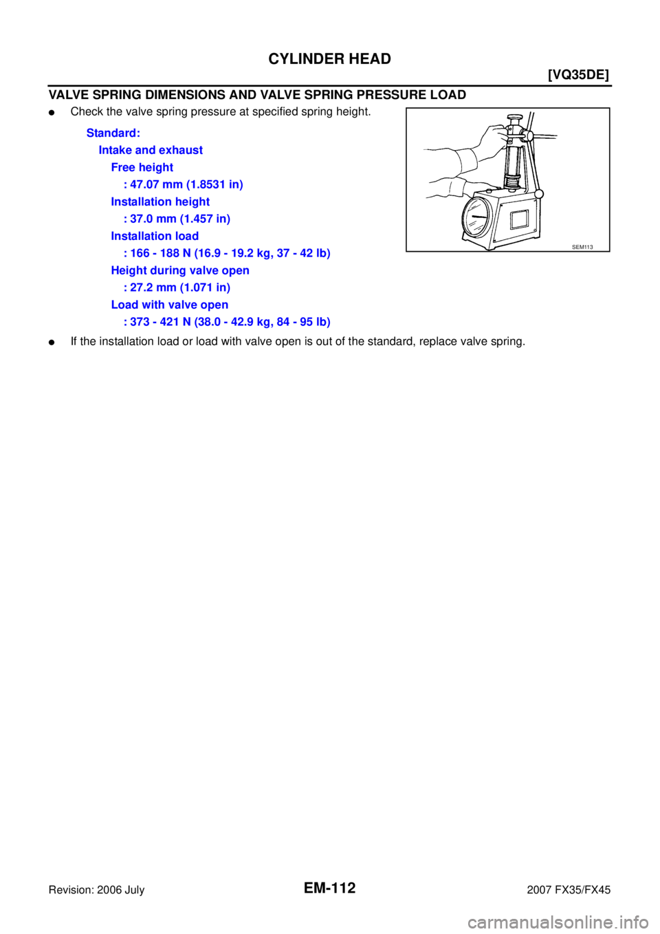
VALVE SPRING DIMENSIONS AND VALVE SPRING PRESSURE LOAD
�Check the valve spring pressure at specified spring height.
�If the installation load or load with valve open is out of the standard, replace valve spring. Standard:
Intake and exhaustFree height: 47.07 mm (1.8531 in)
Installation height : 37.0 mm (1.457 in)
Installation load : 166 - 188 N (16.9 - 19.2 kg, 37 - 42 lb)
Height during valve open : 27.2 mm (1.071 in)
Load with valve open : 373 - 421 N (38.0 - 42.9 kg, 84 - 95 lb)
SEM113
Page 2939 of 4366
![INFINITI FX35 2007 Service Manual CYLINDER BLOCK EM-147
[VQ35DE]
C
D E
F
G H
I
J
K L
M A
EM
Revision: 2006 July 2007 FX35/FX45
CRANKSHAFT PIN JOURNAL DIAMETER
�Measure the outer diameter of crankshaft pin journal with a](/manual-img/42/57018/w960_57018-2938.png "INFINITI FX35 2007 Service Manual CYLINDER BLOCK EM-147
[VQ35DE]
C
D E
F
G H
I
J
K L
M A
EM
Revision: 2006 July 2007 FX35/FX45
CRANKSHAFT PIN JOURNAL DIAMETER
�Measure the outer diameter of crankshaft pin journal with a")
CYLINDER BLOCK EM-147
[VQ35DE]
C
D E
F
G H
I
J
K L
M A
EM
Revision: 2006 July 2007 FX35/FX45
CRANKSHAFT PIN JOURNAL DIAMETER
�Measure the outer diameter of crankshaft pin journal with a
micrometer.
�If out of the standard, measure the connecting rod bearing oil
clearance. Then use undersize bearing. Refer to EM-147,
"CONNECTING ROD BEARING OIL CLEARANCE" .
CRANKSHAFT OUT-OF-ROUND AND TAPER
�Measure the dimensions at four different points as shown in the
figure on each main journal and pin journal with a micrometer.
�Out-of-round is indicated by the difference in the dimensions
between “X” and “Y” at “A” and “B”.
�Taper is indicated by the difference in the dimensions between
“A” and “B” at “X” and “Y”.
�If the measured value exceeds the limit, correct or replace crankshaft.
�If corrected, measure the bearing oil clearance of the corrected main journal and/or pin journal. Then
select the main bearing and/or connecting rod bearing. Refer to EM-148, "
MAIN BEARING OIL CLEAR-
ANCE" and/or EM-147, "CONNECTING ROD BEARING OIL CLEARANCE" .
CRANKSHAFT RUNOUT
�Place V-block on precise flat table, and support the journals on
the both end of crankshaft.
�Place a dial indicator straight up on the No. 3 journal.
�While rotating crankshaft, read the movement of the pointer on a
dial indicator. (Total indicator reading)
�If it exceeds the limit, replace crankshaft.
CONNECTING ROD BEARING OIL CLEARANCE
Method by Calculation
�Install connecting rod bearings to connecting rod and connect-
ing rod cap, and tighten connecting rod bolts to the specified
torque. Refer to EM-129, "
ASSEMBLY" for the tightening proce-
dure.
�Measure the inner diameter of connecting rod bearing with an
inside micrometer.
(Oil clearance) = (Connecting rod bearing inner diameter) – (Crank-
shaft pin journal diameter) Standard : 51.956 - 51.974 mm (2.0455 - 2.0462 in) dia.
PBIC0127E
Limit:
Out-of-round (Difference between “X” and “Y”) : 0.002 mm (0.0001 in)
Taper (Difference between “A” and “B”) : 0.002 mm (0.0001 in)
SBIA0535E
Standard : Less than 0.05 mm (0.0020 in)
Limit : 0.10 mm (0.0039 in)
SEM346D
PBIC1642E
Page 2941 of 4366
![INFINITI FX35 2007 Service Manual CYLINDER BLOCK EM-149
[VQ35DE]
C
D E
F
G H
I
J
K L
M A
EM
Revision: 2006 July 2007 FX35/FX45
�Remove main bearing caps and bearings, and using the scale
on the plastigage bag, measure th](/manual-img/42/57018/w960_57018-2940.png "INFINITI FX35 2007 Service Manual CYLINDER BLOCK EM-149
[VQ35DE]
C
D E
F
G H
I
J
K L
M A
EM
Revision: 2006 July 2007 FX35/FX45
�Remove main bearing caps and bearings, and using the scale
on the plastigage bag, measure th")
CYLINDER BLOCK EM-149
[VQ35DE]
C
D E
F
G H
I
J
K L
M A
EM
Revision: 2006 July 2007 FX35/FX45
�Remove main bearing caps and bearings, and using the scale
on the plastigage bag, measure the plastigage width.
NOTE:
The procedure when the measured value exceeds the limit is
same as that described in the “Method by Calculation”.
MAIN BEARING CRUSH HEIGHT
�When main bearing cap is removed after being tightened to the
specified torque with main bearings installed, the tip end of bear-
ing must protrude. Refer to EM-129, "
ASSEMBLY" for the tight-
ening procedure.
�If the standard is not met, replace main bearings.
CONNECTING ROD BEARING CRUSH HEIGHT
�When connecting rod bearing cap is removed after being tight-
ened to the specified torque with connecting rod bearings
installed, the tip end of bearing must protrude. Refer to EM-129,
"ASSEMBLY" for the tightening procedure.
�If the standard is not met, replace connecting rod bearings.
MAIN BEARING CAP BOLT OUTER DIAMETER
�Measure the outer diameters (“d1 ”, “d2 ”) at two positions as
shown in the figure.
�If reduction appears in “A” range, regard it as “d2 ”.
�If it exceeds the limit (large difference in dimensions), replace
main bearing cap bolt with new one.
PBIC1149E
Standard : There must be crush height.
SEM502G
Standard : There must be crush height.
PBIC1646E
Limit (“d1 ” – “d2 ”) : 0.11 mm (0.0043 in)
PBIC0911E
Page 2947 of 4366
SERVICE DATA AND SPECIFICATIONS (SDS) EM-155
[VQ35DE]
C
D E
F
G H
I
J
K L
M A
EM
Revision: 2006 July 2007 FX35/FX45
CYLINDER HEAD
Unit: mm (in)
Valve Dimensions
Unit: mm (in)
Items Standard Limit
Head surface distortion Less than 0.03 (0.0012) 0.1 (0.004)
Normal cylinder head height “H” 126.3 - 126.5 (4.97 - 4.98) —
PBIC0924E
Valve head diameter “D” Intake 37.0 - 37.3 (1.457 - 1.469)
Exhaust 31.2 - 31.5 (1.228 - 1.240)
Valve length “L” Intake 96.46 (3.7976)
Exhaust 93.99 (3.7004)
Valve stem diameter “d” Intake 5.965 - 5.980 (0.2348 - 0.2354)
Exhaust 5.955 - 5.970 (0.2344 - 0.2350)
Valve seat angle “ α” Intake
45 °15 ′ - 45 °45 ′
Exhaust
Valve margin “T” Intake 1.1 (0.043)
Exhaust 1.3 (0.051)
Valve margin “T” limit 0.5 (0.020)
Valve stem end surface grinding limit 0.2 (0.008)
SEM188
![INFINITI FX35 2007 Service Manual PREPARATION EM-11
[VQ35DE]
C
D E
F
G H
I
J
K L
M A
EM
Revision: 2006 July 2007 FX35/FX45
(—)
TORX socket Removing and installing flywheel
Size: T55
(—)
Manual lift table caddy R](/manual-img/42/57018/w960_57018-2802.png "INFINITI FX35 2007 Service Manual PREPARATION EM-11
[VQ35DE]
C
D E
F
G H
I
J
K L
M A
EM
Revision: 2006 July 2007 FX35/FX45
(—)
TORX socket Removing and installing flywheel
Size: T55
(—)
Manual lift table caddy R")
![INFINITI FX35 2007 Service Manual SERVICE DATA AND SPECIFICATIONS (SDS) EM-155
[VQ35DE]
C
D E
F
G H
I
J
K L
M A
EM
Revision: 2006 July 2007 FX35/FX45
CYLINDER HEAD
Unit: mm (in)
Valve Dimensions
Unit: mm (in)
Items Stand](/manual-img/42/57018/w960_57018-2946.png "INFINITI FX35 2007 Service Manual SERVICE DATA AND SPECIFICATIONS (SDS) EM-155
[VQ35DE]
C
D E
F
G H
I
J
K L
M A
EM
Revision: 2006 July 2007 FX35/FX45
CYLINDER HEAD
Unit: mm (in)
Valve Dimensions
Unit: mm (in)
Items Stand")