Page 2548 of 4366
![INFINITI FX35 2007 Service Manual EC-1172
[VK45DE]
DTC P1212 TCS COMMUNICATION LINE
Revision: 2006 July 2007 FX35/FX45
DTC P1212 TCS COMMUNICATION LINEPFP:47850
DescriptionNBS004CO
NOTE:
�If DTC P1212 is displayed with DTC U1000 or U1 INFINITI FX35 2007 Service Manual EC-1172
[VK45DE]
DTC P1212 TCS COMMUNICATION LINE
Revision: 2006 July 2007 FX35/FX45
DTC P1212 TCS COMMUNICATION LINEPFP:47850
DescriptionNBS004CO
NOTE:
�If DTC P1212 is displayed with DTC U1000 or U1](/manual-img/42/57018/w960_57018-2547.png)
EC-1172
[VK45DE]
DTC P1212 TCS COMMUNICATION LINE
Revision: 2006 July 2007 FX35/FX45
DTC P1212 TCS COMMUNICATION LINEPFP:47850
DescriptionNBS004CO
NOTE:
�If DTC P1212 is displayed with DTC U1000 or U1001, first perform the trouble diagnosis for DTC
U1000, U1001. Refer to EC-820, "
DTC U1000, U1001 CAN COMMUNICATION LINE" .
�If DTC P1212 is displayed with DTC U1010, first perform the trouble diagnosis for DTC U1010.
Refer to EC-823, "
DTC U1010 CAN COMMUNICATION" .
This CAN communication line is used to control the smooth engine operation during the TCS operation. Pulse
signals are exchanged between ECM and “ABS actuator and electric unit (control unit)”.
Be sure to erase the malfunction information such as DTC not only for “ABS actuator and electric unit
(control unit)” but also for ECM after TCS related repair.
On Board Diagnosis LogicNBS004CP
Freeze frame data is not stored in the ECM for this self-diagnosis. The MIL will not light up for this self-
diagnosis.
DTC Confirmation ProcedureNBS004CQ
TESTING CONDITION:
Before performing the following procedure, confirm that battery voltage is more than 10.5V at idle.
WITH CONSULT-II
1. Turn ignition switch ON.
2. Select “DATA MONITOR” mode with CONSULT-II.
3. Start engine and let it idle for at least 10 seconds.
4. If 1st trip DTC is detected, go to EC-1172, "
Diagnostic Proce-
dure" .
WITH GST
Follow the procedure “WITH CONSULT-II” above.
Diagnostic ProcedureNBS004CR
Go to BRC-11, "TROUBLE DIAGNOSIS" .
DTC No. Trouble diagnosis name DTC detecting condition Possible cause
P1212
1212 TCS communication
line ECM can not receive the information
from “ABS actuator and electric unit (con-
trol unit)” continuously.
�Harness or connectors
(The CAN communication line is open or
shorted.)
�ABS actuator and electric unit (control unit)
�Dead (Weak) battery
SEF058Y
Page 2599 of 4366
![INFINITI FX35 2007 Service Manual DTC P1574 ICC VEHICLE SPEED SENSOR EC-1223
[VK45DE]
C
D E
F
G H
I
J
K L
M A
EC
Revision: 2006 July 2007 FX35/FX45
DTC P1574 ICC VEHICLE SPEED SENSORPFP:31036
Component DescriptionNBS004EO INFINITI FX35 2007 Service Manual DTC P1574 ICC VEHICLE SPEED SENSOR EC-1223
[VK45DE]
C
D E
F
G H
I
J
K L
M A
EC
Revision: 2006 July 2007 FX35/FX45
DTC P1574 ICC VEHICLE SPEED SENSORPFP:31036
Component DescriptionNBS004EO](/manual-img/42/57018/w960_57018-2598.png)
DTC P1574 ICC VEHICLE SPEED SENSOR EC-1223
[VK45DE]
C
D E
F
G H
I
J
K L
M A
EC
Revision: 2006 July 2007 FX35/FX45
DTC P1574 ICC VEHICLE SPEED SENSORPFP:31036
Component DescriptionNBS004EO
The ECM receives two vehicle speed signals via CAN communication line. One is sent from “unified meter and
A/C amp.”, and the other is from TCM (Transmission control module). The ECM uses these signals for ICC
control. Refer to ACS-6, "
DESCRIPTION" for ICC functions.
On Board Diagnosis LogicNBS004EP
This self-diagnosis has the one trip detection logic.
The MIL will not light up for this diagnosis.
NOTE:
�If DTC P1574 is displayed with DTC U1000, U1001, first perform the trouble diagnosis for DTC
U1000, U1001. Refer to EC-820, "
DTC U1000, U1001 CAN COMMUNICATION LINE" .
�If DTC P1574 is displayed with DTC U1010, first perform the trouble diagnosis for DTC U1010.
Refer to EC-823, "
DTC U1010 CAN COMMUNICATION" .
�If DTC P1574 is displayed with DTC P0500, first perform the trouble diagnosis for DTC P0500.
Refer to EC-1133, "
DTC P0500 VSS" .
�If DTC P1574 is displayed with DTC P0605, first perform the trouble diagnosis for DTC P0605.
Refer to EC-1148, "
DTC P0605 ECM".
DTC Confirmation ProcedureNBS004EQ
CAUTION:
Always drive vehicle at a safe speed.
NOTE:
If DTC Confirmation Procedure has been previously conducted, always turn ignition switch OFF and wait at
least 10 seconds before conducting the next test.
TESTING CONDITION:
Step 3 may be conducted with the drive wheels lifted in the shop or by driving the vehicle. If a road test
is expected to be easier, it is unnecessary to lift the vehicle.
WITH CONSULT-II
1. Start engine (VDC switch OFF).
2. Select “DATA MONITOR” mode with CONSULT-II.
3. Drive the vehicle at more than 40 km/h (25MPH).
4. If DTC is detected, go to EC-1224, "
Diagnostic Procedure" .
WITH GST
Follow the procedure “WITH CONSULT-II” above.
DTC No. Trouble diagnosis
name DTC detecting condition Possible cause
P1574
1574 ICC vehicle speed
sensor ECM detects a difference between two vehicle
speed signals is out of the specified range.
�Harness or connectors
(The CAN communication line is open or
shorted.)
�Unified meter and A/C amp.
�ABS actuator and electric unit (control unit)
�Wheel sensor
�TCM
�ECM
PBIB2673E
Page 2600 of 4366
EC-1224
[VK45DE]
DTC P1574 ICC VEHICLE SPEED SENSOR
Revision: 2006 July 2007 FX35/FX45
Diagnostic ProcedureNBS004ER
1. CHECK DTC WITH TCM
Check DTC with TCM. Refer to AT- 4 0 , "
ON BOARD DIAGNOSTIC (OBD) SYSTEM" .
OK or NG
OK >> GO TO 2.
NG >> Perform trouble shooting relevant to DTC indicated.
2. CHECK DTC WITH “ABS ACTUATOR AND ELECTRIC UNIT (CONTROL UNIT)”
Refer to BRC-11, "
TROUBLE DIAGNOSIS" .
OK or NG
OK >> GO TO 3.
NG >> Repair or replace.
3. CHECK DTC WITH “UNIFIED METER AND A/C AMP.”
Check combination meter function.
Refer to DI-28, "
UNIFIED METER AND A/C AMP" .
>> INSPECTION END
Page 2601 of 4366
![INFINITI FX35 2007 Service Manual DTC P1574 ASCD VEHICLE SPEED SENSOR EC-1225
[VK45DE]
C
D E
F
G H
I
J
K L
M A
EC
Revision: 2006 July 2007 FX35/FX45
DTC P1574 ASCD VEHICLE SPEED SENSORPFP:31036
Component DescriptionNBS004 INFINITI FX35 2007 Service Manual DTC P1574 ASCD VEHICLE SPEED SENSOR EC-1225
[VK45DE]
C
D E
F
G H
I
J
K L
M A
EC
Revision: 2006 July 2007 FX35/FX45
DTC P1574 ASCD VEHICLE SPEED SENSORPFP:31036
Component DescriptionNBS004](/manual-img/42/57018/w960_57018-2600.png)
DTC P1574 ASCD VEHICLE SPEED SENSOR EC-1225
[VK45DE]
C
D E
F
G H
I
J
K L
M A
EC
Revision: 2006 July 2007 FX35/FX45
DTC P1574 ASCD VEHICLE SPEED SENSORPFP:31036
Component DescriptionNBS004ES
The ECM receives two vehicle speed sensor signals via CAN communication line. One is sent from “unified
meter and A/C amp.”, and the other is from TCM (Transmission control module). The ECM uses these signals
for ASCD control. Refer to EC-697, "
AUTOMATIC SPEED CONTROL DEVICE (ASCD)" for ASCD functions.
On Board Diagnosis LogicNBS004ET
This self-diagnosis has the one trip detection logic.
The MIL will not light up for this diagnosis.
NOTE:
�If DTC P1574 is displayed with DTC U1000, U1001, first perform the trouble diagnosis for DTC
U1000, U1001. Refer to EC-820, "
DTC U1000, U1001 CAN COMMUNICATION LINE" .
�If DTC P1574 is displayed with DTC U1010, first perform the trouble diagnosis for DTC U1010.
Refer to EC-823, "
DTC U1010 CAN COMMUNICATION" .
�If DTC P1574 is displayed with DTC P0500, first perform the trouble diagnosis for DTC P0500.
Refer to EC-1133, "
DTC P0500 VSS"
�If DTC P1574 is displayed with DTC P0605, first perform the trouble diagnosis for DTC P0605.
Refer to EC-1148, "
DTC P0605 ECM"
DTC Confirmation ProcedureNBS004EU
CAUTION:
Always drive vehicle at a safe speed.
NOTE:
If DTC Confirmation Procedure has been previously conducted, always turn ignition switch OFF and wait at
least 10 seconds before conducting the next test.
TESTING CONDITION:
Step 3 may be conducted with the drive wheels lifted in the shop or by driving the vehicle. If a road test
is expected to be easier, it is unnecessary to lift the vehicle.
WITH CONSULT-II
1. Start engine (VDC switch OFF).
2. Select “DATA MONITOR” mode with CONSULT-II.
3. Drive the vehicle at more than 40 km/h (25 MPH).
4. If DTC is detected, go to EC-1226, "
Diagnostic Procedure" .
WITH GST
Follow the procedure “WITH CONSULT-II” above.
DTC No. Trouble diagnosis
name DTC detecting condition Possible cause
P1574
1574 ASCD vehicle speed
sensor ECM detects a difference between two vehicle
speed signals is out of the specified range.
�Harness or connectors
(The CAN communication line is open or
shorted.)
�Unified meter and A/C amp.
�ABS actuator and electric unit (control unit)
�Wheel sensor
�TCM
�ECM
PBIB2673E
Page 2602 of 4366
EC-1226
[VK45DE]
DTC P1574 ASCD VEHICLE SPEED SENSOR
Revision: 2006 July 2007 FX35/FX45
Diagnostic ProcedureNBS004EV
1. CHECK DTC WITH TCM
Check DTC with TCM. Refer to AT- 4 0
.
OK or NG
OK >> GO TO 2.
NG >> Perform trouble shooting relevant to DTC indicated.
2. CHECK DTC WITH “ABS ACTUATOR AND ELECTRIC UNIT (CONTROL UNIT)”
Refer to BRC-11, "
TROUBLE DIAGNOSIS" .
OK or NG
OK >> GO TO 3.
NG >> Repair or replace.
3. CHECK DTC WITH “UNIFIED METER AND A/C AMP.”
Refer to DI-28, "
UNIFIED METER AND A/C AMP" .
>> INSPECTION END
Page 2758 of 4366
EI-14
FRONT BUMPER
Revision: 2006 July 2007 FX35/FX45
FRONT BUMPERPFP:F2022
Removal and InstallationNIS001TO
1. Bumper stay 2. Front bumper guard bar 3. Bumper reinforcement
4. Energy absorber 5. Bumper fascia 6. License plate bracket
7. Bumper center molding 8. Bumper clamp 9. Fillet molding Pawl
PIIB8942E
Page 2759 of 4366

FRONT BUMPER EI-15
C
D E
F
G H
J
K L
M A
B
EI
Revision: 2006 July 2007 FX35/FX45
CAUTION:
Bumper fascia is made of resin. Do not apply strong force to it, and be careful to prevent contact with
oil.
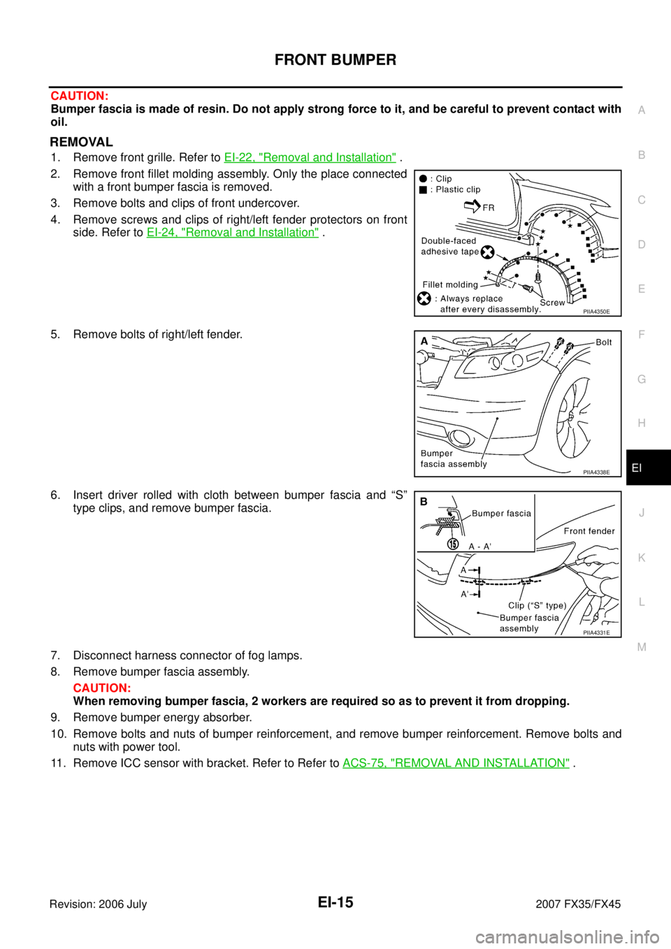
REMOVAL
1. Remove front grille. Refer to EI-22, "Removal and Installation" .
2. Remove front fillet molding assembly. Only the place connected with a front bumper fascia is removed.
3. Remove bolts and clips of front undercover.
4. Remove screws and clips of right/left fender protectors on front side. Refer to EI-24, "
Removal and Installation" .
5. Remove bolts of right/left fender.
6. Insert driver rolled with cloth between bumper fascia and “S” type clips, and remove bumper fascia.
7. Disconnect harness connector of fog lamps.
8. Remove bumper fascia assembly. CAUTION:
When removing bumper fascia, 2 workers are required so as to prevent it from dropping.
9. Remove bumper energy absorber.
10. Remove bolts and nuts of bumper reinforcement, and remove bumper reinforcement. Remove bolts and nuts with power tool.
11. Remove ICC sensor with bracket. Refer to Refer to ACS-75, "
REMOVAL AND INSTALLATION" .
PIIA4350E
PIIA4338E
PIIA4331E
Page 2762 of 4366

EI-18
REAR BUMPER
Revision: 2006 July 2007 FX35/FX45
CAUTION:
Bumper fascia is made of resin. Do not apply strong force to it, and be careful to prevent contact with
oil.
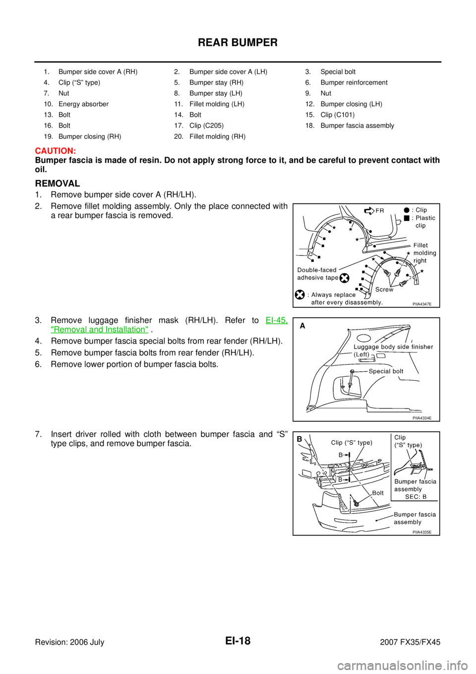
REMOVAL
1. Remove bumper side cover A (RH/LH).
2. Remove fillet molding assembly. Only the place connected with a rear bumper fascia is removed.
3. Remove luggage finisher mask (RH/LH). Refer to EI-45,
"Removal and Installation" .
4. Remove bumper fascia special bolts from rear fender (RH/LH).
5. Remove bumper fascia bolts from rear fender (RH/LH).
6. Remove lower portion of bumper fascia bolts.
7. Insert driver rolled with cloth between bumper fascia and “S” type clips, and remove bumper fascia.
1. Bumper side cover A (RH) 2. Bumper side cover A (LH) 3. Special bolt
4. Clip (“S” type) 5. Bumper stay (RH) 6. Bumper reinforcement
7. Nut 8. Bumper stay (LH) 9. Nut
10. Energy absorber 11. Fillet molding (LH) 12. Bumper closing (LH)
13. Bolt 14. Bolt 15. Clip (C101)
16. Bolt 17. Clip (C205) 18. Bumper fascia assembly
19. Bumper closing (RH) 20. Fillet molding (RH)
PIIA4347E
PIIA4334E
PIIA4335E