Page 3102 of 4366
![INFINITI FX35 2007 Service Manual FAX-16
[AWD]
FRONT DRIVE SHAFT
Revision: 2006 July 2007 FX35/FX45
NOTE:
Refer to component parts location and do not reuse non-reusable parts.
�Check the following item after service.
–Installation](/manual-img/42/57018/w960_57018-3101.png "INFINITI FX35 2007 Service Manual FAX-16
[AWD]
FRONT DRIVE SHAFT
Revision: 2006 July 2007 FX35/FX45
NOTE:
Refer to component parts location and do not reuse non-reusable parts.
�Check the following item after service.
–Installation")
FAX-16
[AWD]
FRONT DRIVE SHAFT
Revision: 2006 July 2007 FX35/FX45
NOTE:
Refer to component parts location and do not reuse non-reusable parts.
�Check the following item after service.
–Installation condition of wheel sensor harness
Removal and Installation (Right Side)NDS000C7
COMPONENTS
REMOVAL
1. Remove tires from vehicle with power tool.
2. Remove undercover with power tool.
3. Remove cotter pin. Then remove lock nut from drive shaft with power tool.
4. Remove wheel sensor harness from strut assembly. Refer to BRC-57, "
WHEEL SENSORS" .
CAUTION:
Do not pull on wheel sensor harness.
5. Remove brake hose lock prate. Then remove brake hose from strut assembly. Refer to BR-11, "
BRAKE
TUBE AND HOSE" .
6. Remove fixing bolts and nuts between strut assembly and steering knuckle with power tool.
7. Using a puller (suitable tool), remove drive shaft from steering knuckle.
CAUTION:
When removing drive shaft, do not apply an excessive
angle to drive shaft joint. Also be careful not to excessively
extend slide joint.
8. Pry off drive shaft from front final drive assembly side as shown in the figure.
INSPECTION AFTER REMOVAL
�Move joint up/down, left/right, and in the axial direction. Check for any rough movement or significant
looseness.
1. Cotter pin 2. Washer 3. Drive shaft
Refer to GI-11, "
Components" , for the symbols in the figure.
PDIA1219E
SDIA0972J
SDIA1489E
Page 3103 of 4366
FRONT DRIVE SHAFT FAX-17
[AWD]
C E F
G H
I
J
K L
M A
B
FA X
Revision: 2006 July 2007 FX35/FX45
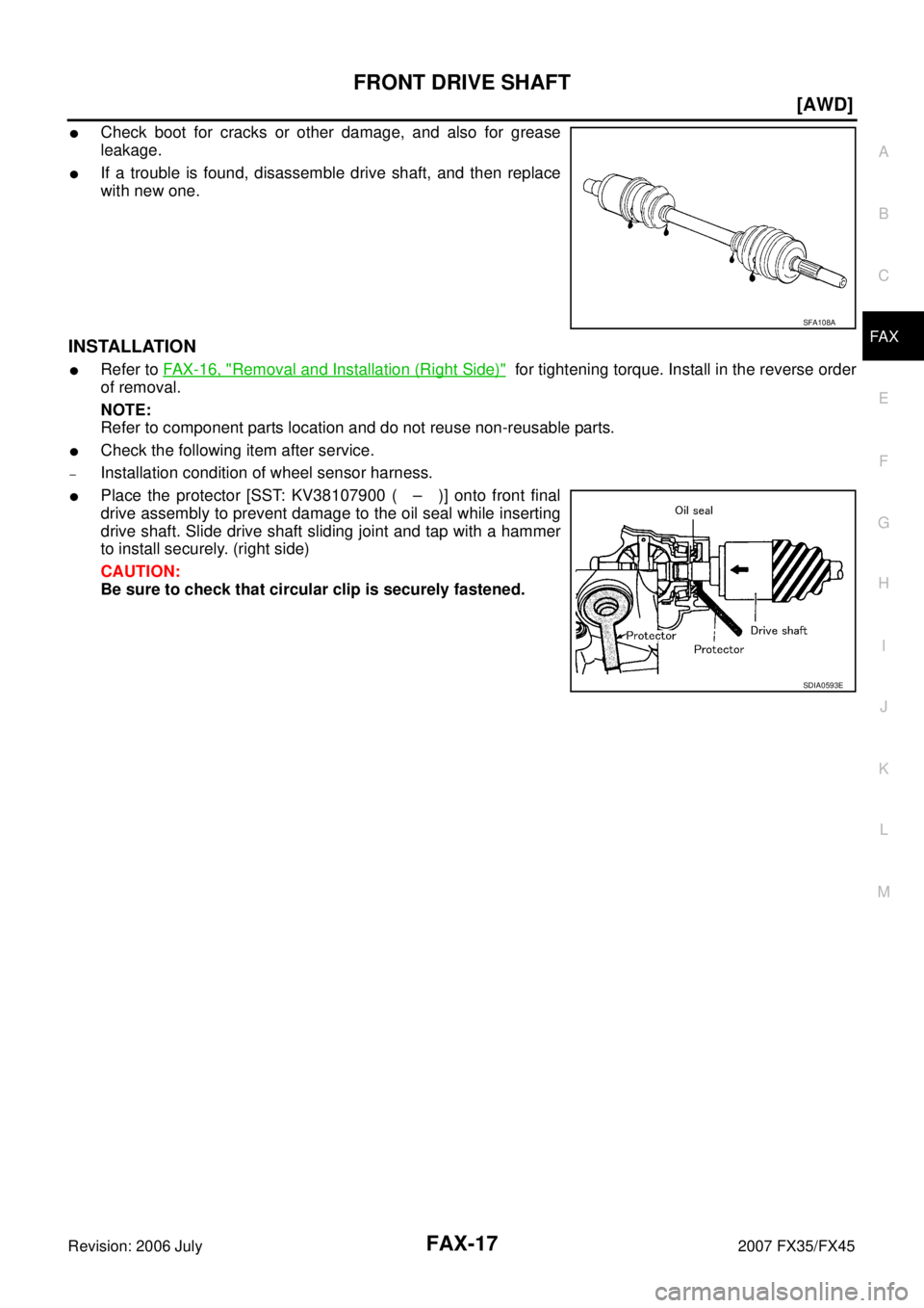
�Check boot for cracks or other damage, and also for grease
leakage.
�If a trouble is found, disassemble drive shaft, and then replace
with new one.
INSTALLATION
�Refer to FAX-16, "Removal and Installation (Right Side)" for tightening torque. Install in the reverse order
of removal.
NOTE:
Refer to component parts location and do not reuse non-reusable parts.
�Check the following item after service.
–Installation condition of wheel sensor harness.
�Place the protector [SST: KV38107900 ( – )] onto front final
drive assembly to prevent damage to the oil seal while inserting
drive shaft. Slide drive shaft sliding joint and tap with a hammer
to install securely. (right side)
CAUTION:
Be sure to check that circular clip is securely fastened.
SFA108A
SDIA0593E
Page 3153 of 4366

FL-1
FUEL SYSTEM
B ENGINE
CONTENTS
C
D E
F
G H
I
J
K L
M
SECTION
A
FL
Revision: 2006 July 2007 FX35/FX45
FUEL SYSTEM
PREPARATION ........................................................... 2
Commercial Service Tools ................................... ..... 2
FUEL SYSTEM ...................................................... ..... 3
Checking Fuel Lines ............................................ ..... 3
General Precautions ........................................... ..... 3
FUEL LEVEL SENSOR UNIT, FUEL FILTER AND
FUEL PUMP ASSEMBLY ...................................... ..... 4
Components ........................................................ ..... 4
Removal and Installation ..................................... ..... 4
REMOVAL ........................................................ ..... 4
INSTALLATION ................................................ ..... 6
INSPECTION AFTER INSTALLATION ............ ..... 7 Components ........................................................
..... 8
Disassembly and Assembly ................................. ..... 8
DISASSEMBLY ................................................ ..... 8
ASSEMBLY ...................................................... ..... 9
FUEL TANK ........................................................... ... 10
Components ........................................................ ... 10
Removal and Installation ..................................... ... 10
REMOVAL ........................................................ ... 10
INSTALLATION ................................................ ... 11
INSPECTION AFTER INSTALLATION ............. ... 11
SERVICE DATA AND SPECIFICATIONS (SDS) ... ... 12
Standard and Limit ............................................... ... 12
FUEL TANK ...................................................... ... 12
Page 3156 of 4366

FL-4
FUEL LEVEL SENSOR UNIT, FUEL FILTER AND FUEL PUMP ASSEMBLY
Revision: 2006 July 2007 FX35/FX45
FUEL LEVEL SENSOR UNIT, FUEL FILTER AND FUEL PUMP ASSEMBLYPFP:17042
ComponentsNBS004II
Removal and InstallationNBS006SU
REMOVAL
WARNING:
Read “General Precautions” when working on the fuel system. Refer to FL-3, "
General Precautions" .
1. Check fuel level on fuel gauge. If fuel gauge indicates more than the level as shown in the figure (full or almost full), drain fuel
from fuel tank until fuel gauge indicates level as shown in the fig-
ure or below.
NOTE:
Because fuel will be spilled when removing main and sub fuel
level sensor units for the top of the fuel is above the main and
sub fuel level sensor units installation surface.
�As a guide, fuel level becomes the position as shown in the
figure or below when approximately 20 (5-1/4 US gal, 4-3/8
Imp gal) of fuel are drained from fuel tank.
�In a case that fuel pump does not operate, perform the follow-
ing procedure.
a. Insert hose of less than 25 mm (0.98 in) in diameter into fuel filler tube through fuel filler opening to draw fuel from fuel filler tube.
b. Disconnect fuel filler hose from fuel filler tube. Refer to FL-10, "
FUEL TANK" .
c. Insert fuel tube into fuel tank through fuel filler hose to draw fuel from fuel tank.
2. Release the fuel pressure from the fuel lines. Refer to EC-85, "
FUEL PRESSURE RELEASE" (VQ35DE)
or EC-747, "
FUEL PRESSURE RELEASE" (VK45DE).
1. Retainer 2. Main fuel level sensor unit, fuel filter -
and fuel pump assembly 3. O-ring
4. Sub fuel level sensor unit
PBIC1585E
PBIC1575E
Page 3157 of 4366
FUEL LEVEL SENSOR UNIT, FUEL FILTER AND FUEL PUMP ASSEMBLY FL-5
C
D E
F
G H
I
J
K L
M A
FL
Revision: 2006 July 2007 FX35/FX45
3. Open fuel filler lid.
4. Open filler cap and release the pressure inside fuel tank.
5. Remove rear seat cushion. Refer to SE-104, "
REAR SEAT" .
6. Peel off floor carpet, then remove inspection hole cover for main and sub fuel level sensor units by turning clips clockwise by 90
degrees.
7. Disconnect harness connector and fuel feed tube.
Disconnect quick connector as follows:
�Hold the sides of connector, push in tabs and pull out tube.
�If quick connector sticks to tube of main fuel level sensor unit,
push and pull quick connector several times until they start to
move.Then disconnect them by pulling.
PBIC1576E
PBIC1577E
SFE562A
Page 3158 of 4366

FL-6
FUEL LEVEL SENSOR UNIT, FUEL FILTER AND FUEL PUMP ASSEMBLY
Revision: 2006 July 2007 FX35/FX45
CAUTION:
�Quick connector can be disconnected when the tabs
are completely depressed. Do not twist it more than
necessary.
�Do not use any tools to disconnected quick connector.
�Keep resin tube away from heat. Be especially careful
when welding near the resin tube.
�Prevent acid liquid such as battery electrolyte, etc.
from getting on resin tube.
�Do not bend or twist resin tube during installation and
disconnection.
�Do not remove the remaining retainer on hard tube (or
the equivalent) except when resin tube or retainer is
replaced.
�When resin tube or hard tube (or the equivalent) is
replaced, also replace retainer with new one.
�To keep the connecting portion clean and to avoid
damage and foreign materials, cover them completely
with plastic bags or something similar.
8. Remove main fuel level sensor unit, fuel filter and fuel pump assembly, and sub fuel level sensor unit as follows:
CAUTION:
�Do not bend float arm during removal.
�Avoid impacts such as falling when handling components.
a. Removal of main fuel level sensor unit, fuel filter and fuel pump assembly:
i. Remove retainer.
ii. Raise main fuel level sensor unit, fuel filter and fuel pump assembly, and using snap ring pliers, remove fuel hose connec-
tor.
CAUTION:
Be careful not to damage fuel hose connector by expanding
them excessively.
b. Removal of sub fuel level sensor unit:
i. Remove retainer.
ii. Raise and release sub fuel level sensor unit to remove.
INSTALLATION
Note to the following, and install in the reverse order of removal. Retainer color: White
SBIA0504E
PBIC0163E
PBIC1578E
Page 3159 of 4366

FUEL LEVEL SENSOR UNIT, FUEL FILTER AND FUEL PUMP ASSEMBLY FL-7
C
D E
F
G H
I
J
K L
M A
FL
Revision: 2006 July 2007 FX35/FX45
Main and Sub Fuel Level Sensor Unit
�When installing fuel hose connector insert them fully until a click
sound of full stopper engagement is heard.
�Face main and sub fuel level sensor units as shown in the fig-
ure, and install them with the knock pin on back aligned with pin
hole on fuel tank.
�Install retainer so that its notch becomes parallel with the notch
on fuel tank.
�Tighten retainer mounting bolts evenly.
Quick Connector
Connect quick connector as follows:
1. Check the connection for damage or any foreign materials.
2. Align the connector with the tube, then insert the connector straight into the tube until a click sound is heard.
3. After connecting, make sure that the connection is secure by following method.
�Pull the tube and the connector to make sure they are
securely connected.
�Visually confirm that the two retainer tabs are connected to
the connector.
INSPECTION AFTER INSTALLATION
Use the following procedure to check for fuel leaks.
PBIC1579E
PBIC1065E
PBIC1652E
PBIC1653E
Page 3160 of 4366
, then check connections for leaks by applying")
FL-8
FUEL LEVEL SENSOR UNIT, FUEL FILTER AND FUEL PUMP ASSEMBLY
Revision: 2006 July 2007 FX35/FX45
1. Turn ignition switch “ON” (with engine stopped), then check connections for leaks by applying fuel pres-
sure to fuel piping.
2. Start engine and let it idle and make sure there are no fuel leaks at the fuel system connections.
ComponentsNBS004IJ
Disassembly and AssemblyNBS005S3
CAUTION:
Sub fuel level sensor unit cannot be disassembled and should be replaced as a unit.
DISASSEMBLY
Remove fuel level sensor unit as follows.
1. Disconnect harness connector.
�Hold connector by fingers and pull it out, because there is no
stopper release tab.
2. Using suitable tool, pull up tabs points as shown in the figure (two points) to release the lock.
CAUTION:
Be careful not to damage it.
3. After fixing tabs are disengaged, slide fuel level sensor unit out in direction shown by the arrow.
CAUTION:
Do not disassemble fuel filter and fuel pump assembly.
1. Fuel level sensor unit 2. Fuel filter and fuel pump assembly
PBIC1081E
PBIC1078E
PBIC1654E
PBIC1080E