Page 4252 of 4366
TF-48
TRANSFER ASSEMBLY
Revision: 2006 July 2007 FX35/FX45
11. Remove snap ring from front case.
12. Remove mainshaft bearing from front case, using a drift.
13. Remove drive chain and front drive shaft while tapping front drive shaft with plastic hammer.
CAUTION:
Be careful not to tap drive chain.
14. Remove oil gutter from rear case.
15. Remove oil cover bolt and sensor fixing bolt from rear case. And then, remove oil cover.
PDIA0267E
Tool number : KV38100300 (J-25523)
PDIA0256E
PDIA0257E
PDIA0261E
SDIA2403E
Page 4258 of 4366
TF-54
TRANSFER ASSEMBLY
Revision: 2006 July 2007 FX35/FX45
4. Install snap ring to rear case.
CAUTION:
Do not reuse snap ring.
5. Install mainshaft assembly to rear case, using a drift. CAUTION:
ATF should be applied to contact surface of mainshaft and
rear bearing.
6. Install O-ring to transfer assembly harness connector. CAUTION:
�Do not reuse O-ring.
�Apply ATF to O-ring.
7. Install transfer assembly harness connector into rear case.
8. Install retainer to transfer assembly harness connector.
9. Set temperature sensor and tighten bolt to the specified torque. Refer to TF-45, "
COMPONENTS" .
10. Hold electric controlled coupling harness with oil cover hold plate, install oil cover to rear case, and tighten bolt to the speci-
fied torque. Refer to TF-45, "
COMPONENTS" .
CAUTION:
The harness should be guided by a cut portion.
PDIA0263E
Tool number : ST35321000 ( — )
SDIA2368E
SDIA1597E
SDIA2404E
Page 4275 of 4366
TIRE PRESSURE MONITORING SYSTEM WT-11
C
D
F
G H
I
J
K L
M A
B
WT
Revision: 2006 July 2007 FX35/FX45
TIRE PRESSURE MONITORING SYSTEMPFP:40720
System ComponentsNES000GP
System DescriptionNES000GQ
TRANSMITTER
A sensor-transmitter integrated with a valve is installed on a wheel,
and transmits a detected air pressure signal in the form of a radio
wave.
REMOTE KEYLESS ENTRY RECEIVER
The remote keyless entry receiver receives the air pressure signal
transmitted by the transmitter in each wheel.
SEIA0599E
SEIA0521E
SEIA0431E
Page 4343 of 4366

FRONT WIPER AND WASHER SYSTEM WW-37
C
D E
F
G H
I
J
L
M A
B
WW
Revision: 2006 July 2007 FX35/FX45
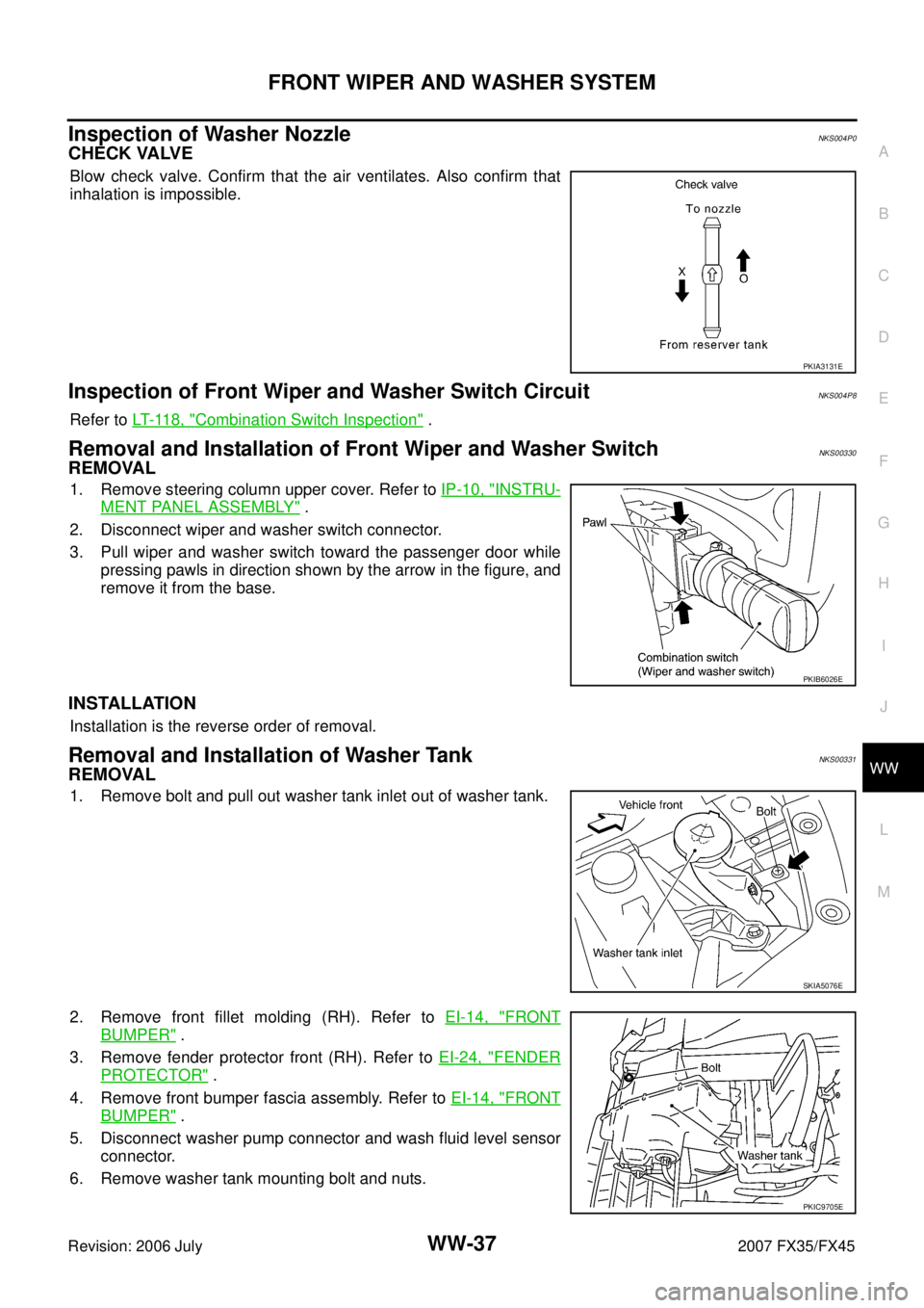
Inspection of Washer NozzleNKS004P0
CHECK VALVE
Blow check valve. Confirm that the air ventilates. Also confirm that
inhalation is impossible.
Inspection of Front Wiper and Washer Switch CircuitNKS004P8
Refer to LT- 11 8 , "Combination Switch Inspection" .
Removal and Installation of Front Wiper and Washer SwitchNKS00330
REMOVAL
1. Remove steering column upper cover. Refer to IP-10, "INSTRU-
MENT PANEL ASSEMBLY" .
2. Disconnect wiper and washer switch connector.
3. Pull wiper and washer switch toward the passenger door while pressing pawls in direction shown by the arrow in the figure, and
remove it from the base.
INSTALLATION
Installation is the reverse order of removal.
Removal and Installation of Washer TankNKS00331
REMOVAL
1. Remove bolt and pull out washer tank inlet out of washer tank.
2. Remove front fillet molding (RH). Refer to EI-14, "
FRONT
BUMPER" .
3. Remove fender protector front (RH). Refer to EI-24, "
FENDER
PROTECTOR" .
4. Remove front bumper fascia assembly. Refer to EI-14, "
FRONT
BUMPER" .
5. Disconnect washer pump connector and wash fluid level sensor connector.
6. Remove washer tank mounting bolt and nuts.
PKIA3131E
PKIB6026E
SKIA5076E
PKIC9705E