Page 4314 of 4366
 status, and controls related systems such a")
WW-8
FRONT WIPER AND WASHER SYSTEM
Revision: 2006 July 2007 FX35/FX45
COMBINATION SWITCH READING FUNCTION
Description
�BCM reads combination switch (wiper) status, and controls related systems such as head lamps and wip-
ers, according to the results.
�BCM reads information of a maximum of 20 switches by combining five output terminals (OUTPUT 1-5)
and five input terminals (INPUT 1-5).
Operation Description
�BCM activates transistors of output terminals (OUTPUT 1-5) periodically and, and allows current to flow in
turn.
�If any (1 or more) switches are turned ON, circuit of output terminals (OUTPUT 1-5) and input terminals
(INPUT 1-5) becomes active.
�At this time, transistors of output terminals (OUTPUT 1-5) are activated to allow current to flow. When volt-
age of input terminals (INPUT 1-5) corresponding to that switch changes, interface in BCM detects volt-
age change, and BCM determines that switch is ON.
BCM - Operation Table of Combination Switches
BCM reads operation status of combination switch using combinations shown in table below.
PKID0853E
SKIA4959E
Page 4315 of 4366
FRONT WIPER AND WASHER SYSTEM WW-9
C
D E
F
G H
I
J
L
M A
B
WW
Revision: 2006 July 2007 FX35/FX45
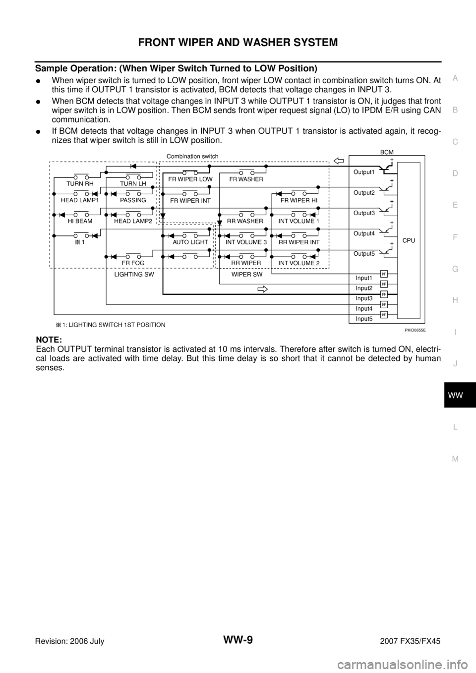
Sample Operation: (When Wiper Switch Turned to LOW Position)
�When wiper switch is turned to LOW position, front wiper LOW contact in combination switch turns ON. At
this time if OUTPUT 1 transistor is activated, BCM detects that voltage changes in INPUT 3.
�When BCM detects that voltage changes in INPUT 3 while OUTPUT 1 transistor is ON, it judges that front
wiper switch is in LOW position. Then BCM sends front wiper request signal (LO) to IPDM E/R using CAN
communication.
�If BCM detects that voltage changes in INPUT 3 when OUTPUT 1 transistor is activated again, it recog-
nizes that wiper switch is still in LOW position.
NOTE:
Each OUTPUT terminal transistor is activated at 10 ms intervals. Therefore after switch is turned ON, electri-
cal loads are activated with time delay. But this time delay is so short that it cannot be detected by human
senses.
PKID0855E
Page 4326 of 4366
NKS0032G
CONSULT-II can display each diagnostic item using the diagnostic test mode shown following.
CO")
WW-20
FRONT WIPER AND WASHER SYSTEM
Revision: 2006 July 2007 FX35/FX45
CONSULT-II Functions (BCM)NKS0032G
CONSULT-II can display each diagnostic item using the diagnostic test mode shown following.
CONSULT-II BASIC OPERATION
Refer to GI-38, "CONSULT-II Start Procedure" .
WORK SUPPORT
Operation Procedure
1. Touch “WIPER” on “SELECT TEST ITEM” screen.
2. Touch “WORK SUPPORT” on “SELECT DIAG MODE” screen.
3. Touch “WIPER SPEED SETTING” on “SELECT WORK ITEM” screen.
4. Touch “START”.
5. Touch “CHANGE SETT”.
6. The setting will be changed and “CUSTOMIZING COMPLETED” will be displayed.
7. Touch “END”.
Display Item List
DATA MONITOR
Operation Procedure
1. Touch “WIPER” on “SELECT TEST ITEM” screen.
2. Touch “DATA MONITOR” on “SELECT DIAG MODE” screen.
3. Touch either “ALL SIGNALS” or “SELECTION FROM MENU” on “SELECT MONITOR ITEM” screen.
4. When “SELECTION FROM MENU” is selected, touch items to be monitored. When “ALL SIGNALS” is selected, all the items will be monitored.
5. Touch “START”.
6. Touch “RECORD” while monitoring, then the status of the monitored item can be recorded. To stop recording, touch “STOP”.
Display Item List
BCM diagnosis position Diagnosis mode Description
WIPER WORK SUPPORT Changes the setting for each function.
DATA MONITOR Displays BCM input data in real time. ACTIVE TEST Device operation can be checked by applying a drive signal to device.
BCM SELF-DIAG RESULTS BCM performs self-diagnosis of CAN communication.
CAN DIAG SUPPORT MNTR The result of transmit/receive diagnosis of CAN communication can be read.
Item Description CONSULT-II Factory setting
WIPER SPEED SETTING Vehicle speed sousing type wiper control mode can be changed in this
mode. Vehicle speed sousing type wiper control mode between two ON/OFF. ON
×
OFF —
ALL SIGNALS Monitors all the signals.
SELECTION FROM MENU Selects items and monitors them.
Monitor item Contents
IGN ON SW “ON/OFF” Displays status (ignition switch IGN position: ON/other: OFF) of ignition switch judged from
the ignition switch signal.
IGN SW CAN “ON/OFF” Displays status (ignition switch IGN position: ON/other: OFF) of ignition switch judged from
the ignition switch signal (CAN communication lines).
FR WIPER HI “ON/OFF” Displays status (front wiper switch high position: ON/other: OFF) of front wiper high switch
judged from the front wiper switch signal.
FR WIPER LOW “ON/OFF” Displays status (front wiper switch low position: ON/other: OFF) of front wiper low switch
judged from the front wiper switch signal.