2007 Hyundai Terracan lights
[x] Cancel search: lightsPage 192 of 291
3 WHAT TO DO IN AN EMERGENCY
4IF THE ENGINE OVERHEATS
!
5. Start the engine in the car with the
discharged battery using the nor- mal starting procedure. After the engine starts, leave the jumper cables connected and let the enginerun at fast idle or about 2000 rpm for several minutes.
6. Carefully remove the jumper cables in the reverse order of attachment.
If you do not know why your battery became discharged (because the lights were left on, etc.), have the charging system checked by your Hyundaidealer. D030A02HP-AAT If your temperature gauge indicates overheating, you experience a loss of power, or hear loud pinging or knock- ing, the engine is probably too hot. Ifthis happens to you, you should:
1. Pull off the road and stop as soon as
it is safe to do so.
2. Place the gear selector lever in "P"
(automatic), or neutral (manual transmission) and set the parking brake. If the air conditioning is on, turn it off.
3. If engine coolant is running out un- der the car or steam is coming outfrom under the hood, stop the en-gine. Do not open the hood until the engine coolant has stopped running or the steaming has stopped. If thereis no visible loss of coolant and no steam, leave the engine running and check to be sure the enginecooling fan is operating. If the fan is not running, turn the engine off. 4. Check to see if the water pump drive
belt is missing. If it is not missing, check to see that it is tight. If the drive belt seems to be satisfactory, check for engine coolant leakingfrom the radiator, hoses or under the car. (If the air conditioning had been in use, it is normal for coldwater to be draining from it when you stop).
WARNING:
While the engine is running, keephands and clothing away from mov- ing parts such as the fan and drivebelts to prevent injury.
Page 228 of 291
6
DO-IT-YOURSELF MAINTENANCE
5GENERAL CHECKS
G020A02HP-GAT
Engine Compartment
The following should be checked regu- larly:
o Engine oil level and condition
o Transmission fluid level and condi- tion
o Brake fluid level
o Clutch fluid level
o Engine coolant level
o Windshield washer fluid level
o Accessory drive belt condition
o Engine coolant hose condition
o Fluid leaks
(on or below components)
o Power steering fluid level
o Battery condition
o Climate control air filter condition G020B01A-AAT
Vehicle Exterior
The following should be checked
monthly:
o Overall appearance and condition
o Wheel condition and wheel nut torque
o Exhaust system condition
o Light condition and operation
o Windshield glass condition
o Wiper blade condition
o Paint condition and body corrosion
o Fluid leaks
o Door and hood lock condition
o Tire pressure and condition
(including spare tire) G020C01HP-GAT Vehicle Interior The following should be checked each time when the vehicle is driven:
o Lights operation
o Windshield wiper operation
o Horn operation
o Defroster, heating system operation
(and air conditioning, if installed)
o Steering operation and condition
o Mirror condition and operation
o Turn signal operation
o Accelerator pedal operation
o Brake operation, including parking
brake
o Manual transmission operation, in-
cluding clutch operation
o Automatic transmission operation, including "Park" mechanism opera-tion
o Seat control condition and opera-
tion
o Seat belt condition and operation
o Sun visor operation If you notice anything that does not operate correctly or appears to be functioning incorrectly, inspect it care- fully and seek assistance from yourHyundai dealer if service is needed.
Page 248 of 291

6
DO-IT-YOURSELF MAINTENANCE
25
G200B02HP-GAT
Replacing Accessory Fuses
The fuse box for the lights and other
electrical accessories will be found under the dashboard on the driver’s side. Inside the box you will find a list showing the circuits protected by eachfuse. If any of your car's lights or other
electrical accessories stop working, ablown fuse could be the reason. If the fuse has burned out, you will see that the metal strip inside the fuse hasburned through. If you suspect a blown fuse, follow this procedure: G200B01HP
!
A fusible link will melt if the electrical
circuits from the battery are ever over- loaded, thus preventing damage to the entire wiring harness. (This could be caused by a short in the systemdrawing too much current.) If this ever happens, have a Hyundai dealer determine the cause, repair the sys-tem and replace the fusible link. The fusible links are located in a relay box for easy inspection.
CAUTION:
When replacing a fusible link, never use anything but a new fusible link with the same or lower amper-age rating. Never use a piece of wire or a higher-rated fusible link. This could result in serious dam-age and create a fire hazard. 3. Be sure to check all other fuses,
even if you find one that appears tohave burned out.
1. Turn off the ignition and all other
switches.
2. Open the fuse box and examine each fuse. Remove each fuse bypulling it toward you (a small "fusepuller" tool is contained in the relay and fuse box of the engine room to simplify this operation).
HHP4002
Page 249 of 291
6 DO-IT-YOURSELF MAINTENANCE
26
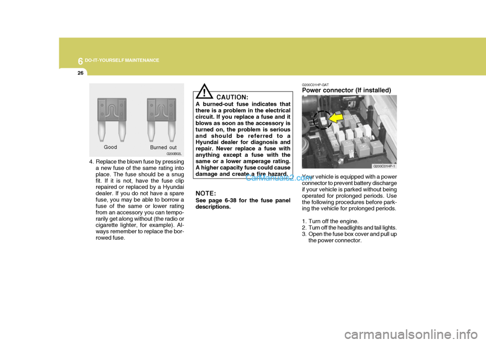
4. Replace the blown fuse by pressing
a new fuse of the same rating into place. The fuse should be a snugfit. If it is not, have the fuse clip repaired or replaced by a Hyundai dealer. If you do not have a sparefuse, you may be able to borrow a fuse of the same or lower rating from an accessory you can tempo-rarily get along without (the radio or cigarette lighter, for example). Al- ways remember to replace the bor-rowed fuse. Good
G200B02L
Burned out CAUTION:
A burned-out fuse indicates thatthere is a problem in the electricalcircuit. If you replace a fuse and it blows as soon as the accessory is turned on, the problem is seriousand should be referred to a Hyundai dealer for diagnosis and repair. Never replace a fuse withanything except a fuse with the same or a lower amperage rating. A higher capacity fuse could causedamage and create a fire hazard. NOTE: See page 6-38 for the fuse panel descriptions.
! G200C01HP-GAT
Power connector (If installed)
Your vehicle is equipped with a power connector to prevent battery discharge if your vehicle is parked without being operated for prolonged periods. Usethe following procedures before park- ing the vehicle for prolonged periods.
1. Turn off the engine.
2. Turn off the headlights and tail lights.
3. Open the fuse box cover and pull up the power connector.
G200C01HP-1
Page 250 of 291
6
DO-IT-YOURSELF MAINTENANCE
27CHECKING THE BATTERY
!
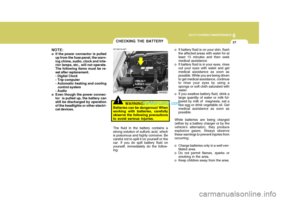
G210A01A-AAT
WARNING:
Batteries can be dangerous! When
working with batteries, carefully observe the following precautionsto avoid serious injuries. o If battery fluid is on your skin, flush
the affected areas with water for atleast 15 minutes and then seek medical assistance.
o If battery fluid is in your eyes, rinse out your eyes with water and getmedical assistance as soon as possible. While you are being drivento get medical assistance, continue to rinse your eyes by using a sponge or soft cloth saturated withwater.
o If you swallow battery fluid, drink a large quantity of water or milk fol- lowed by milk of magnesia, eat a raw egg or drink vegetable oil. Getmedical assistance as soon as possible.
While batteries are being charged (either by a battery charger or by thevehicle's alternator), they produce explosive gases. Always observe these warnings to prevent injuries fromoccurring:
o Charge batteries only in a well ven- tilated area.
o Do not permit flames, sparks or smoking in the area.
o Keep children away from the area.
The fluid in the battery contains a
strong solution of sulfuric acid, whichis poisonous and highly corrosive. Becareful not to spill it on yourself or the car. If you do spill battery fluid on yourself, immediately do the follow-ing: HHP5020
NOTE:
o If the power connector is pulled up from the fuse panel, the warn-ing chime, audio, clock and inte- rior lamps, etc., will not operate. The following items must be re-set after replacement.- Digital Clock - Trip computer
- Automatic heating and cooling
control system
- Audio
o Even though the power connec- tor is pulled up, the battery can still be discharged by operation of the headlights or other electri-cal devices.
Page 260 of 291
6
DO-IT-YOURSELF MAINTENANCE
37
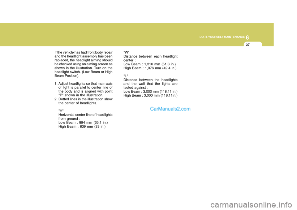
"W" Distance between each headlight center :Low Beam : 1,316 mm (51.8 in.) High Beam : 1,076 mm (42.4 in.) "L" Distance between the headlightsand the wall that the lights are tested against : Low Beam : 3,000 mm (118.11 in.) High Beam : 3,000 mm (118.11in.)
If the vehicle has had front body repair
and the headlight assembly has beenreplaced, the headlight aiming should be checked using an aiming screen as shown in the illustration. Turn on theheadlight switch. (Low Beam or High Beam Position).
1. Adjust headlights so that main axis of light is parallel to center line of the body and is aligned with point "P" shown in the illustration.
2. Dotted lines in the illustration show the center of headlights. "H" Horizontal center line of headlightsfrom ground :Low Beam : 894 mm (35.1 in.) High Beam : 839 mm (33 in.)
Page 285 of 291
10INDEX
2
A Air bag ....................................................................... 1-47
Air Cleaner Filter ........................................................ 6-13
Air Conditioning Care ........................................................................ 6-22
Operation ..................................................... 1-111, 6-22
Switch ................................................................... 1-111
Antenna ................................................................... 1-141
Ashtray ...................................................................... 1-81
Audio Fault Code ..................................................... 1-138
Automatic Heating and Cooling Control System ...... 1-113
BBattery .............................................................. 2-26, 6-27
Bi-Level Heating ...................................................... 1-109
Brake Anti-lock brake system (ABS) ................................ 2-21
Checking the brakes ............................................... 6-20
Fluid ........................................................................ 6-20
Practices ................................................................ 2-22
Breaking-In your New Hyundai .................................... 1-3
C
Care of Cassette Tapes .......................................... 1-140
Care of D iscs .......................................................... 1-139
Cargo Security Screen .............................................. 1-94
Cassette Tape Player Operation (H240) .................. 1-125
Cassette Tape Player Operation (H280) .................. 1-130
Catalytic Converter ...................................................... 7-3 CD Auto changer
(H280) ................................. 1-92, 1-135
Center Console Compartment ....................................1-87
Center console armrest .......................................... 1-87
Center console box ................................................. 1-87
Child Restraint System .............................................. 1-39
Child-Protector Rear Door Lock ................................. 1-12
Cigarette Lighter ........................................................ 1-79
Climate Control air Filter ................................. 1-119, 6-23
Clock ......................................................................... 1-78
Clutch Checking fluid ......................................................... 6-21
Combination Light Daytime running lights ............................................ 1-74
Headlight flasher ..................................................... 1-75
Headlight swi tch ..................................................... 1-73
High-beam switch ................................................... 1-74
Lane change si gnal ................................................. 1-73
Parking light auto cut ............................................. 1-74
Turn signal operation .............................................. 1-73
Compact Disc Player Operation (H280) ................... 1-132
Cooling Fans ............................................................. 6-29
Corrosion protection Cleaning the interior .................................................. 4-6
Protecting your Hyundai from corrosion ................... 4-2
Washing and waxing ................................................. 4-4
Cruise Control .......................................................... 1-101
Page 287 of 291

10INDEX
4
Headlight Leveling Device S ystem ..........................1-100
Heating and Ventilation ............................................ 1-105
Air flow control ........................................... 1-106, 1-117
Temperature control .... .......................................... 1-108
High-Mounted Rear Stop Light ...................................1-95
Hood Release ............................................................ 1-97
Horn ........................................................................... 1-99
I Ignition Sw itch ............................................................. 2-3
Immobilizer S ystem ..................................................... 1-5
Limp Home Procedures ................................... 1-7, 1-9
Key ................................................................... 1-5, 1-8
Indicator and Warning Lights.................................... 1-58
Instrument Cluster and Indicator Li ghts................... 1-54
Instrument Panel Light Control (Rheo stat)............... 1-79
Interior Light .............................................................. 1-85
Intermittent Wiper ..................................................... 1-77
J Jump Starting .............................................................. 3-3
K
Key .............................................................................. 1-4 If you lose your keys ............................................. 3-17
Positions ................................................................... 2-4 L
Limited-Slip Differential
.............................................. 2-22
Luggage Compartment
Cargo Security Screen ........................................... 1-94
Light ........................................................................ 1-93
Net .......................................................................... 1-93
M Maintenance Intervals Explanation of scheduled maintenance items ......... 5-9
Maintenance under severe usage conditions .......... 5-8 Scheduled maintenance ........................................... 5-4
Service requ irements............................................... 5-2
Mirrors Day/night inside rearview ....... .................................1-90
Outside rearvi ew ..................................................... 1-88
Multimeter .................................................................. 1-69
Altimeter ................................................................. 1-70
Barometer ............................................................... 1-72
Digital Clock ........................................................... 1-72
Electrical azimuth compass ................................... 1-70
Relative altimeter .................................................... 1-71
O
Odometer ................................................................... 1-67
P Parking Brake ............................................................ 1-91
Part-time 4WD Opera tion ........................................... 2-14