Page 206 of 331
Remove the key from the shift
lock release slot, then reinstall the
cover. Make sure the notch on the
cover is on the instrument panel
side. Press the brake pedal, and
restart the engine.
Set the parking brake.
Insert a key into the shift lock
release slot.If you need to use the shif t lock
release, it means your vehicle is
developing a problem. Have it
checked by your dealer.
Make sure the ignition switch is in
the LOCK (0) position.
This allows you to move the shif t
lever out of Park if the normal
method of pushing on the brake
pedal and pulling the shif t lever does
not work.
Putaclothonthenotchof the
shif t lock release slot cover. Using
a small f lat-tipped screwdriver or a
metal f ingernail f ile, caref ully pry
on the notch of the cover to
remove it. Push down on the key while you
pull the shif t lever towards you
and move it out of Park to neutral.6.
1.
2.
3.
4.
5.
Shif t L ock Release
Automatic Transmission
202
SHIFT LOCK RELEASE SLOT
COVER
Page 221 of 331

There are two common types of
trailer brakes: surge and electric.
Surge brakes are common f or boat
trailers, since the brakes will get wet.
If you choose electric brakes, be
sure they are electronically actuated.
Do not attempt to tap into your
vehicle’s hydraulic system. No
matter how successf ul it may seem,
any attempt to attach trailer brakes
to your vehicle’s hydraulic system
will lower braking ef f ectiveness and
create a potential hazard.
Seeyourtrailermanufacturerfor
more inf ormation on installing
electric brakes. Honda requires that any trailer with
a total trailer weight of 1,000 lbs (455
kg) or more have its own brakes.A f actory installed, 4-pin gray
connector is located under the
instrument panel near the top of the
parking brake pedal. This connector
has all of the circuits required to
install most electric trailer brake
controllers. A jumper harness to
adapt your electric trailer brake
controller to the vehicle is included
with the optional Genuine Honda
trailer hitch kit. To obtain a trailer
hitch kit, see your dealer.
Have a qualif ied mechanic install
your trailer brake controller
f ollowing the trailer brake controller
manuf acturer’s instructions. Failure
to properly install the trailer brake
controller may increase the distance
it takes f or you to stop your vehicle
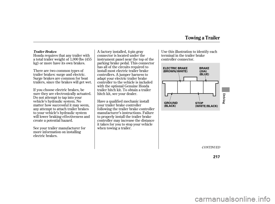
when towing a trailer.Use this illustration to identif y each
terminal in the trailer brake
controller connector.
CONT INUED
Trailer Brakes
Towing a Trailer
Driving
217
BRAKE
(20A)
(BLUE)
GROUND
(BLACK)
ELECTRIC BRAKE
(BROWN/WHITE)
STOP
(WHITE/BLACK)
Page 242 of 331
You can change the display to the
engine oil life display, or the
odometer and trip meter by pushing
the SELECT button on the
instrument panel.
All maintenance items displayed in
the trip meter are in code. For an
explanation of these maintenance
codes, see page . Your dealer will reset the display
af ter completing the required
maintenance service. You will see
‘‘OIL LIFE 100 %’’ on the inf ormation
display the next time you turn the
ignition switch to the ON (II)
position.
If maintenance service is done by
someone other than your dealer,
reset the maintenance minder as
f ollows:
Press the SELECT button
repeatedly until the engine oil lif e
display or the service message is
displayed. Turn the ignition switch to the ON
(II) position.
1.
2.
242
Maintenance Main Items and Sub
Items
Resetting the Engine Oil Lif e
Display
Maintenance Minder
238
MAINTENANCE MAIN ITEM
MAINTENANCE SUB ITEMS
Page 287 of 331

Diagnosing why the engine won’t
start falls into two areas, depending
on what you hear when you turn the
ignition switch to the START (III)
position: Check
the transmission interlock.
The transmission must be in Park
or neutral or the starter will not
operate.
Turn the ignition switch to the ON
(II) position. Turn on the
headlights, and check their
brightness. If the headlights are
very dim or do not come on at all,
the battery is discharged. See
on page . If
the headlights dim noticeably or
go out when you try to start the
engine, either the battery is
discharged or the connections are
co rroded. Check the condition of
the battery and terminal connec-
tions (see page ). You can
then try jump starting the vehicle
from a booster battery (see page
).
In this case, the starter motor’s
speed sounds normal, or even faster
than normal, when you turn the
ignition switch to the START (III)
position, but the engine does not run.
Are you using a properly coded
key? An improperly coded key will
cause the immobilizer system
indicator in the instrument panel
to blink rapidly (see page ).
Turn
the ignition switch to the
START (III) position. If the
headlights do not dim, check the
condition of the fuses. If the fuses
areOK,thereisprobably
something wrong with the
electrical circuit for the ignition
switch or starter motor. You will
need a qualified technician to
determine the problem. See on page .
Check these things: When you turn the ignition switch to
the START (III) position, you do not
hear the normal noise of the engine
trying to start. You may hear a
clicking sound, a series of clicks, or
nothing at all. You can hear the starter motor
operating normally, or the starter
motor sounds like it is spinning
f aster than normal, but the engine
does not start up and run. You hear nothing, or almost
nothing. The engine’s starter
motor does not operate at all, or
operates very slowly.
81
284
296 270
284
CONT INUED
Jump Starting T he Starter Operates Normally
Emergency T owing
Nothing Happens or the Starter
Motor Operates Very Slowly
If theEngineWon’tStart
T aking Care of t he Unexpect ed
283
Page 325 of 331

�Î�Î
CONT INUED
..................................................
Keys .80
.......................
Label, Certif ication .300
.................
Lane Change, Signaling . 76
..................
Lap/Shoulder Belts . 14, 19
...........................
Light Control Dial .76
Ignition
..............................................
Keys .80
...........................................
Switch .82
............
Timing Control System . 308
........................
Immobilizer System .81
.........
Important Safety Precautions . 6
...................................
In-Bed Trunk .95
....................
Emergency Opener .96
............................
Open Indicator .69
.........
Indicators, Instrument Panel . 59
...............
ABS (Anti-lock Brake) . 63
.......................
A/T Temperature .66
....................
Back Window Open . 69
.............................
Bed Lights On .69
Brake (Parking and Brake ....................................
System) .63
........................
Charging System .62
.............................
Cruise Control .65
...................................
Door Open .64
DRL (Daytime Running ..................................
Lights) .65
...................................
High Beam .65
....................
In-Bed Trunk Open .69
........
Key (Immobilizer System) . 63
.....................................
Lights On .66
......................................
Low Fuel .65 ........................
Low Oil Pressure .62
......................
Low Tire Pressure .68
..................
Maintenance Minder . 67
Malf unction Indicator Lamp .......................................
(MIL) .62
...........................
Side Airbag Of f .62
.......................................
Seat Belt .61
...............................................
SRS .62
..............................
Tailgate Open .64
...............
Tire Pressure Monitor . 68
.............................
TPMS System .68
Turn Signal and Hazard ...................................
Warning .64
............................
VSA Activation .67
.................................
VSA System .67
..........................................
VTM-4 .66
..............................
Washer Level .65
..................
Individual Map Lights . 119
...............................
Inf ant Restraint .37
......................................
Inf ant Seats .37
...................
Inf lation, Proper Tire . 266
........................
Inf ormation Display .70
.........
Engine Oil Lif e Indicator . 235
...........
Mainte nance Items . 238, 242
.................................
Inside Mirror .110
.............................
Inspection, Tire .266 ........................
Instrument Panel . 3, 58
........
Instrument Panel Brightness . 78
...............................
Interior Lights .118
........................................
Introduction .i
................
Jacking Up the Vehicle . 277
.......................................
Jack, Tire .275
................................
Jump Starting .284
Index
J
L K
INDEX
V