Page 227 of 268

�µStart the vehicle. If the starter
motor still operates slowly, check
that the jumper cables have good
metal-to-metal contact.
Keep the ends of the jumper cables
away from each other and any metal
on the vehicle until everything is
disconnected. Otherwise, you may
cause an electrical short.
If the booster battery is in another
vehicle, have an assistant start
that vehicle and run it at a fast idle. Once your vehicle is running,
disconnect the negative cable f rom
your vehicle, then f rom the
booster battery. Disconnect the
positive cable f rom your vehicle,
then from the booster battery.
If your vehicle’s 12 volt battery is
disconnected or goes dead, the IMA
battery level gauge reading will not
be correct the next time you turn the
ignition switch to the ON (II)
position. It will show less than the
actual level temporarily. It will show
the correct level af ter you drive f or
at least 30 minutes.
Connect the second jumper cable
to the negative ( ) terminal on
the booster battery. Connect the
other end to the grounding strap
as shown. Do not connect this
jumper cable to any other part of
the engine. 7. 6.
4.
5.
Jump Starting
224
Page 232 of 268

If the indicator comes on repeatedly,
even though it may turn off as you
continue driving, have your vehicle
checked by your dealer as soon as
possible.
If
the indicator comes on
while driving, it means one
of the engine’s emissions
control systems may have a problem.
Even though you may feel no
difference in your vehicle’s
performance, it can reduce your fuel
economy and cause increased
emissions. Continued operation may
cause serious damage. If
the battery in your vehicle has
been disconnected or gone dead,
these codes are erased. It takes at
least three days of driving under
various conditions to set the codes
again.
To check if they are set, turn the
ignition switch to the ON (II)
position, without starting the engine.
The malfunction indicator lamp will
come on for 20 seconds. If it then
goes off, the readiness codes are set.
If it blinks five times, the readiness
codes are not set. If possible, do not
take your vehicle for a state
emissions test until the readiness
codes are set. Refer to
for more
info rmation (see page ).
Your
vehicle has certain ‘‘readiness
codes’’ that are part of the on-board
diagnostics for the emissions
systems. In some states, part of the
emissions testing is to make sure
these codes are set. If they are not
set, the test cannot be completed.
If
you have recently refueled your
vehicle, the indicator coming on
could be due to a loose or missing
fuel fill cap. You will also see a
‘‘CHECK FUEL CAP’’ message on
the information display. Tighten the
cap until it clicks at least once (see
page ). Tightening the cap will
not turn the indicator of f
immediately; it takes at least three
days of normal driving. 151
250State
Emissions T esting
Readiness Code
Malf unction Indicator L amp
T aking Care of t he Unexpect ed
229
If you keep driving with the
Malf unction Indicator Lamp on, you
can damage your vehicle’s emissions
controls and engine. Those repairs may
not be covered by your vehicle’s
warranties. This indicator may also
come on with the ‘‘D’’ indicator.
Page 233 of 268

If the ABS indicator comes on with
the brake system indicator, have
your vehicle inspected by your
dealer immediately.
However,
if the brake pedal does not
feel normal, you should take
immediate action. A problem in one
part of the system’s dual circuit
design will still give you braking at
two wheels. You will feel the brake
pedal go down much farther before
the vehicle begins to slow down, and
you will have to press harder on the
pedal.
Slow down by shifting to a lower
gear, and pull to the side of the road
when it is safe. Because of the long
distance needed to stop, it is
hazardous to drive the vehicle. You
should have it to wed and repaired as
soon as possible (see
on page ).
If you must drive the vehicle a short
distance in this condition, drive
slowly and carefully.
The
brake system
indicator normally
comes on when
you turn the ignition switch to the
ON (II) position and as a reminder to
check the parking brake. It will stay
on if you do not fully release the
parking brake.
If the brake system indicator comes
on while driving, the brake fluid level
is probably low. Press lightly on the
brake pedal to see if it feels normal.
If it does, check the brake fluid level
thenexttimeyoustopataservice
station (see page ).
If the f luid level is low, take your
vehicle to a dealer, and have the
brake system inspected f or leaks or
worn brake pads. If the regenerate brake system
indicator (amber) comes on with the
parking brake system indicator (red)
with the parking brake released,
there may be a malfunction with the
power-assist f eature. When the
power-assist f eature malf unctions,
the brake indicator (red) comes on
and a buzzer sounds f or a second.
The power-assist f eature may stop
when the brake ef f ect is weak. Stop
your vehicle immediately at a saf e
place and contact a dealer.
196
237Emergency
Towing
Brake System Indicator
230
Canada
U.S.
Page 235 of 268
Turn the ignition switch to the
LOCK (0) position. Make sure the
headlights and all oth er
accessories are off.
Remove the cover from the fuse
box.
If
something electrical in your
vehicle stops working, the first thing
youshouldcheckforisablownfuse.
Determine f rom the chart on pages and , or the diagram on the
fuse box lid, which fuse or fuses
control that device. Check those
f uses f irst, but check all the f uses
bef ore deciding that a blown f use is
the cause. Replace any blown f uses,
and check if the device works.
Check each of the large f uses in
the primary under-hood f use box
by looking through the top at the
wire inside. Remove the screws
with a Phillips-head screwdriver.
1.
2. 3.
235
236
Checking and Replacing Fuses
Fuses
232
BLOWN
FUSE BLOWN
Page 238 of 268
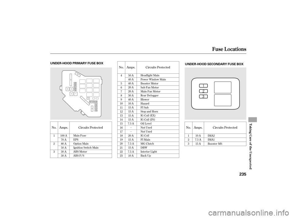
�µ
�µNo.
Amps.
No. Amps. Circuits Protected
No. Amps. Circuits Protected
Circuits Protected
1
2
3
100 A
70 A
80 A
50 A
30 A
30 A
1
2
3
10 A
7.5 A 15 A IMA2
IMA1
Booster MS
4
5
6
7
8
9
10
11
12
13
14
15
16
17
18
19
20
21
22
23 50 A
40 A
40 A
20 A
20 A
30 A
40 A
10 A
15 A
15 A
15 A
15 A
7.5 A
20 A
15 A
7.5 A 15 A
7.5 A 10 A Headlight Main
Power Window Main
Booster Motor
Sub Fan Motor
Main Fan Motor
Rear Defogger
Blower
Hazard
FI Sub
Stop and Horn
IG Coil (EX)
IG Coil (IN)
Oil Level
Not Used
Not Used
IG Coil
FI Main
MG Clutch
DBW
Interior Light
Back Up
Main Fuse
EPS
Option Main
Ignition Switch Main
ABS Motor
ABS F/S
Fuse Locations
T aking Care of t he Unexpect ed
235
UNDER-HOOD PRIMARY FUSE BOX
UNDER-HOOD SECONDARY FUSE BOX
Page 240 of 268

�µ
�µ
CONT INUED
If , due to damage, your vehicle must
be towed with the f ront wheels on
the ground, do this:
Release the parking brake.
Start the engine.
ShifttoD,thentoN.
Turn of f the engine.
With the f ront wheels on the ground,
it is best to tow the vehicle no farther
than 50 miles (80 km), and keep the
speedbelow35mph(55km/h).
If your vehicle needs to be towed,
call a prof essional towing service or
organization. Never tow your vehicle
with just a rope or chain. It is very
dangerous.
Therearetwowaystotowyour
vehicle:
The tow
truck uses two pivoting arms that go
under the tires (f ront) and lif t them
of f the ground. The other two tires
remain on the ground. The operator
loads your vehicle on the back of a
truck. Leave the ignition switch in the
ACCESSORY (I) position so the
steering wheel does not lock.
Wheel-lif t Equipment
Flat -bed Equipment
T his is an
acceptable way to tow your
vehicle. T his is the best way to
transport your vehicle.
Emergency Towing
T aking Care of t he Unexpect ed
237
Improper towing preparation will
damage the transmission. Follow the
above procedure exactly. If you cannot
shif t the transmission or start the
engine, your vehicle must be
transported with the f ront wheels of f
the ground.
Page 241 of 268
Emergency Towing
238
The steering system can be damaged if
the steering wheel is locked. Leave the
ignition switch in the ACCESSORY (I)
position, and make sure the steering
wheel turns f reely bef ore you begin
towing.
Trying to lif t or tow your vehicle by the
bumpers will cause serious damage.
The bumpers are not designed to
support the vehicle’s weight.
Page 242 of 268

Thediagramsinthissectiongive
you the dimensions and capacities of
your vehicle and the locations of the
identif ication numbers. It also
includes inf ormation you should
know about your vehicle’s tires and
emissions control systems.................
Identif ication Numbers .240
................................
Specif ications .242
DOT Tire Quality Grading
......................
(U.S. Vehicles) .244
Unif orm Tire Quality ..................................
Grading .244
.................................
Treadwear .244
......................................
Traction .244
.............................
Temperature .245
.................................
Tire Labeling .246 .......................
Emissions Controls . 247
.....................
The Clean Air Act . 247
Crankcase Emissions Control ....................................
System .247
Evaporative Emissions Control ....................................
System .247
Onboard Ref ueling Vapor ................................
Recovery .247
...
Exhaust Emissions Controls .248
....................
PGM-FI System .248
Ignition Timing Control
................................
System .248
Exhaust Gas Recirculation ...................
(EGR) System .248
Three Way Catalytic ...........................
Converter .248
....................
Replacement Parts .248
..
Three Way Catalytic Converter .249
..............
State Emissions Testing .250
T echnical Inf ormation
Technical Inf ormation
239
 position. Make sure the
headlights and all oth er
accessories are off.
Remove the cover from the fuse
box.
If
something electrical in your
vehicle s")

position, and make sure the steering
wheel turns f reely bef ore")