2007 FORD FIESTA engine
[x] Cancel search: enginePage 993 of 1226

Automatic Transmission/Transaxle -
Vehicles With: 4Speed Automatic
307-01 -33 Transmission (AW81-40) 307-01 -33
DESCRIPTION AND OPERATION
This is influenced by the following variables: Vehicle
speed,
Engine load, Transmission fluid temperature.
Accelerator pedal position, The following are actuated:
Transmission input speed, SSA shift solenoid valve,
Vehicle speed,
Transmission fluid temperature,
Selector lever position.
The
following are actuated:
Main
regulating valve.
Reverse gear safety strategy
SSB shift solenoid valve.
Torque reduction when pulling away
In order to protect the clutches against excessively
high torque when pulling away, the PCM reduces
the engine torque in response to a request from
the transmission
control.
If the accelerator pedal is depressed while the
The transmission control unit prevents shifts into vehicle is pulling away, then the transmission reverse gear while the vehicle is driving forwards, control unit sends a corresponding signal as otherwise serious transmission damage can be requesting a torque reduction via the CAN databus. caused.
The reverse gear safety strategy is active when This
is influenced by the
following variables:
reverse gear is engaged with the selector lever at ' Selector lever position,
vehicle speeds in excess of 11 kmlh. Accelerator pedal position,
In this
case the transmission control unit actuates ' Engine speed,
the shift timing solenoid valve, as a result of which Transmission input speed,
the actuating pressure does not reach the reverse
. Vehicle speed. gear clutch or the reverse gear brake.
The following are actuated:
The reverse gear safety strategy is deactivated
PCM (torque reduction request signal via the
when the vehicle speed is below 9 kmlh. The
actuating pressure can then reach the reverse gear CAN
databus).
clutch and the reverse gear brake and the gearshift
into reverse gear is performed.
Selector lever positions
This is influenced by the following variables:
Vehicle speed,
Selector lever position.
The
following are actuated:
Shift timing solenoid valve.
Selector lever position "P"
No gear is engaged in selector lever position "P".
The parking
pawl is engaged manually via the
selector lever cable and the selector shaft.
Avoidance of gearshift judder during
engagement of a transmission range Selector
lever position "R"
In order to prevent gearshift judder when moving The reverse gear is eWaged in selector lever
the selector lever from N to D, the transmission position "R.
control unit initially shifts into
2nd gear instead of
1 st gear, and then immediately shifts back into I st
gear before the gearshift process is finished. Selector lever position "N"
This reduces the amount of gearshift judder during No gear is engaged in selector lever position WNW. engagement of a forward drive range.
The powertrain is not blocked. This is influenced by the following variables:
Selector lever position,
Accelerator pedal position,
Transmission input speed,
2006.0 Fiesta 1212006 G380530en
procarmanuals.com
Page 994 of 1226

Automatic Transmission/Transaxle -
Vehicles With: 4Speed Automatic
307-01 -34 Transmission (AW81-40) 307-01 -34
DESCRIPTION AND OPERATION
Selector lever position "D" In selector lever position "2" engine braking is
effective when the vehicle is coasting.
In selector lever position
"D" the transmission
control will allow all gears to be engaged provided
the overdrive switch is not operated.
Selector lever position "1"
If the overdrive switch is pressed then the
Only the first gear is engaged when the selector
transmission control prevents gearshifts into 4th
lever is in position ,,. gear or shifts back into 3rd gear.
Selector lever position "2"
If the selector lever is moved to position "1" at
higher speeds than are permitted for first gear, then
the transmission control delays the downshift until
the vehicle speed has slowed down enough.
-
Only the second gear is engaged when the selector In selector lever position ,, engine braking is lever is in position "2". Gearshifts into 1st gear are effective when the vehicle is not permitted.
If the selector lever is moved to position
"2" at
higher speeds than are permitted for second gear,
then the transmission control delays the downshift until the vehicle speed has slowed down enough.
Signal transmission on the CAN databus
CAN Low
E48 1 88
Item Description Item Description
I 1 1 Transmission control unit 1 3 1 Instrument cluster
2006.0 Fiesta 1~2006 G380530en
2 PCM 4 DLC
procarmanuals.com
Page 995 of 1226

Automatic Transmission/Transaxle -
Vehicles With: 4Speed Automatic
307-01 -35 Transmission (AW81-40) 307-01 -35
DESCRIPTION AND OPERATION
Engine speed
1 The engine speed is detected by the crankshaft
position (CKP) sensor and passed on to the PCM.
The engine speed is transmitted from the PCM via
the CAN
databus to the transmission control unit.
The transmission control unit uses this signal for:
Torque reduction during gearshifts,
Pressure control during gearshifts.
Engine load
The PCM determines a load signal which is
transmitted via the CAN
databus to the
transmission control unit.
The transmission control unit uses this signal for:
Torque reduction during gearshifts,
Pressure control during gearshifts,
Shift timing adaptation during upshifts,
Shift timing adaptation during shifts from 3rd to
4th gear,
Hill climb mode,
( ' Hill descent mode. ' ,
Torque reduction request signal
Before performing a gearshift, the transmission
control unit sends a signal via the CAN
databus to
the PCM requesting a torque reduction.
The PCM then reduces the engine torque, ensuring
that the gearshift is as smooth and judder-free as
possible.
Brake signal
The PCM receives a signal from the stoplamp
switch when the brake pedal is depressed.
This signal is transmitted via the CAN
databus to
the transmission control unit.
The transmission control unit uses this signal for:
Gearshift control,
Engagement of the TCC
Accelerator pedal position
The PCM receives the current accelerator pedal
position signal from the Accelerator Pedal Position
(APP) sensor.
This signal is transmitted via the CAN
databus to
the transmission control unit.
The transmission control unit uses this signal for:
Controlling the main line pressure,
Gearshift control,
Engagement of the TCC,
Shift timing adaptation during upshifts,
Shift timing adaptation during shifts from 3rd to
4th gear,
Shift timing adaptation during shifts from 4th to
3rd gear,
Avoidance of gearshift judder during
engagement of a transmission range,
Torque reduction when pulling away.
Coolant temperature
The coolant temperature is detected by the Engine
Coolant Temperature (ECT) sensor and passed
on to the PCM.
This signal is transmitted via the CAN
databus to
the transmission control unit.
The transmission control unit uses this signal for:
Cold start mode,
Engagement of the TCC
Selector lever position
The transmission control unit transmits the selector
lever position to the instrument cluster.
The instrument cluster uses the signal to send a
request for a warning tone to the GEM when the
selector lever is not in position "P" and the driver's
door is opened.
-
2006.0 Fiesta 1212006 G380530en
procarmanuals.com
Page 1002 of 1226
Automatic Transmission/Transaxle -
Vehicles With: 4-Speed Automatic
Transmission
(AW81-40)
DESCRIPTION AND OPERATION
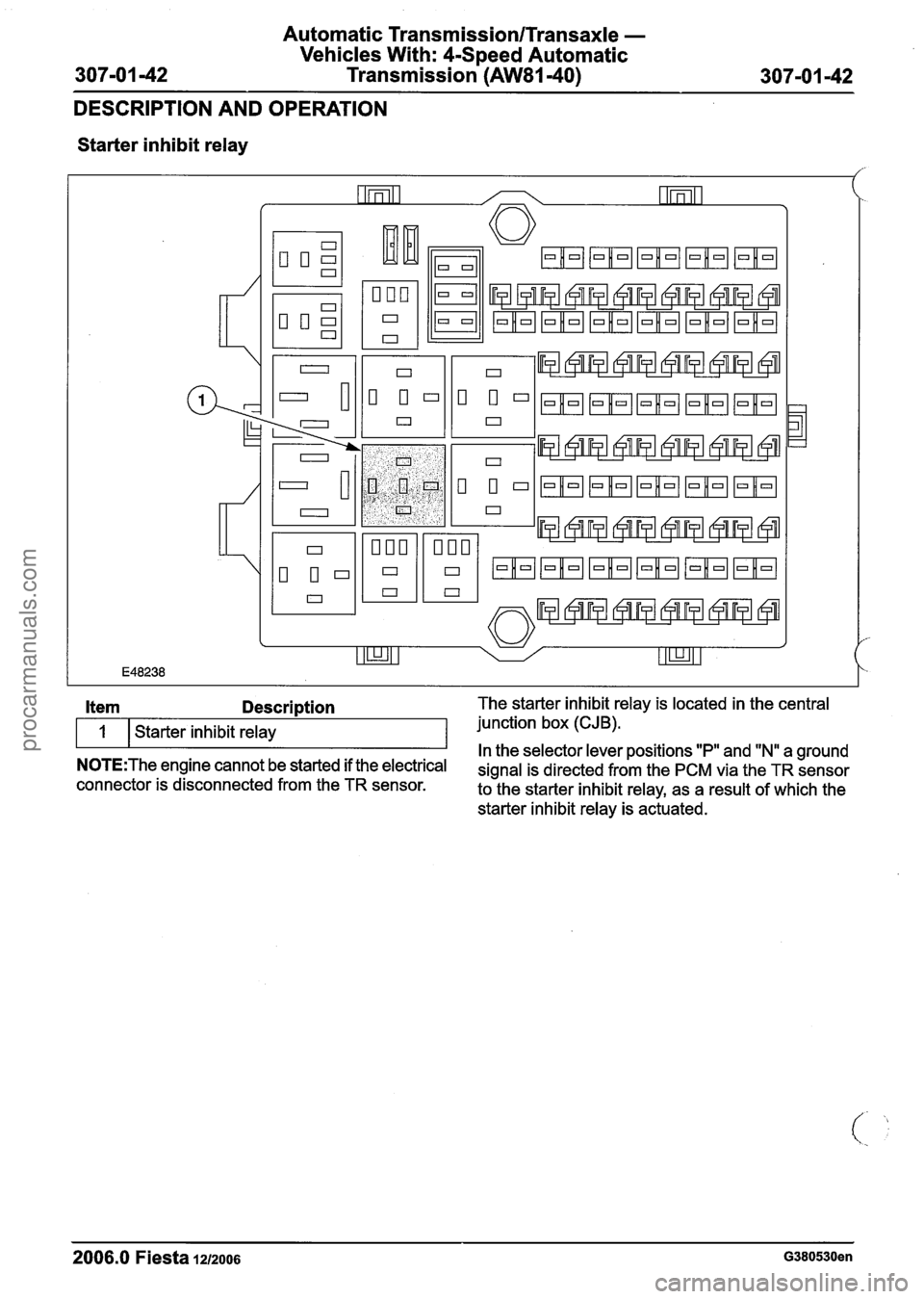
Starter inhibit relay
2006.0 Fiesta
12/2006 G380530en
Item Description The starter inhibit relay is located in the central
1 Starter inhibit relay junction
box (CJB).
In the selector lever positions "P" and "Nu a ground N0TE:The engine cannot be started if the electrical signal is directed from the PCM via the TR sensor connector is disconnected from the TR sensor.
to the starter inhibit relay, as a result of which the
starter inhibit relay is actuated.
procarmanuals.com
Page 1003 of 1226
Automatic Transmission/Transaxle -
Vehicles With: 4-Speed Automatic
307-01 -43 Transmission (AW81-40) 307-01 -43
DESCRIPTION AND OPERATION
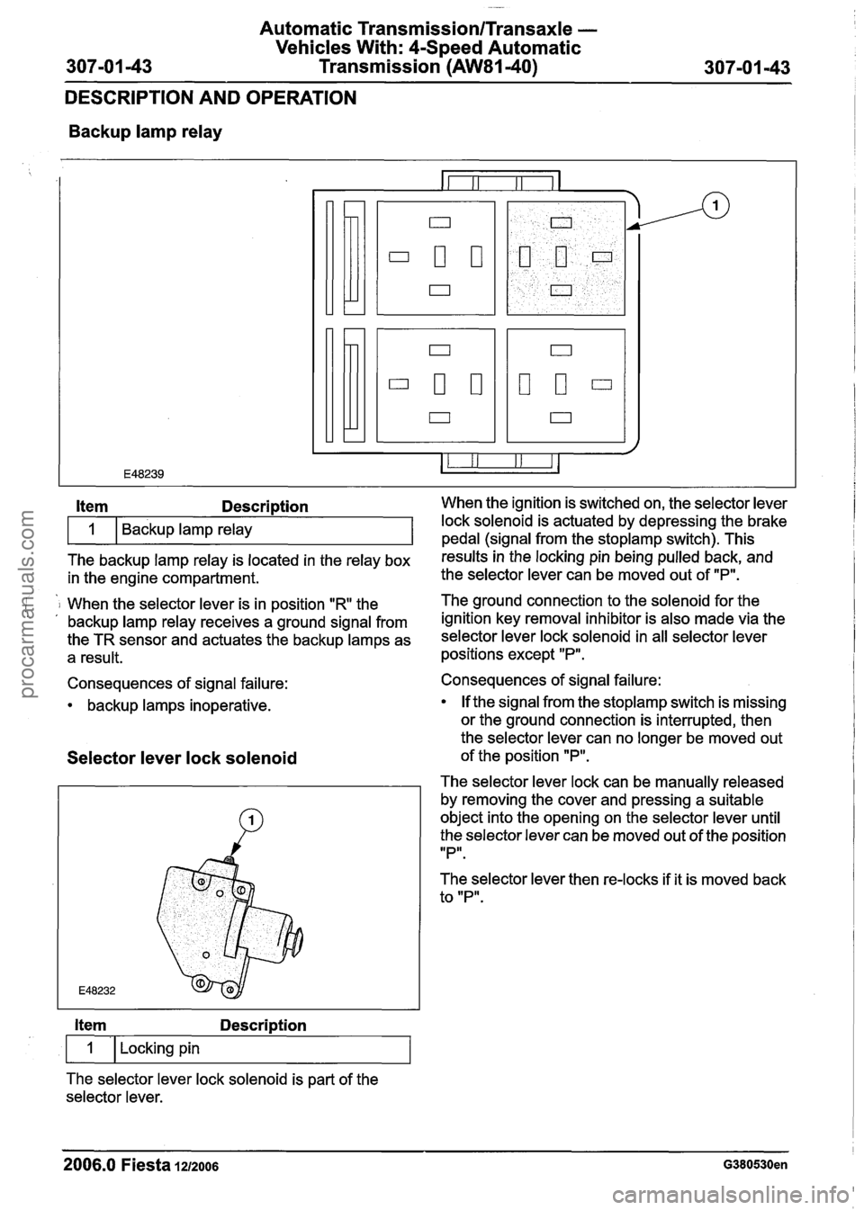
Backup lamp relay
The backup lamp relay is located in the relay box results inthe locking pin being pulled back, and
in the engine compartment. the
selector lever can be moved out of "P".
Item Description When the ignition is switched on, the selector lever
i 1 When the selector lever is in position "R the The ground connection to the solenoid for
the . , backup lamp relay receives a ground signal from ignition key removal inhibitor is also made via the
the TR sensor and actuates the backup lamps as selector lever lock solenoid in all selector lever
a result. positions except "P".
1
Consequences of signal failure:
backup lamps inoperative. Backup lamp relay
Selector
lever lock solenoid
lock solenoid is actuated by depressing the brake
pedal (sianal from the stoplamp switch). This
Item Description
1 I Locking pin
The selector lever lock solenoid is part of the
selector lever. Consequences of signal failure:
If the signal from the
stoplamp switch is missing
or the ground connection is interrupted, then
the selector lever can no longer be moved out
of the position
"P".
The selector lever lock can be manually released
by removing the cover and pressing a suitable
object into the opening on the selector lever until
the selector lever can be moved out of the position
IIPlr.
The selector lever then re-locks if it is moved back
to "P".
2006.0 Fiesta 1212006 G380530en
procarmanuals.com
Page 1006 of 1226
Automatic Transmission/Transaxle -
Vehicles With: 4Speed Automatic
307-01 -46 Transmission
(AW81-40) 307101 -46
DIAGNOSIS AND TESTING
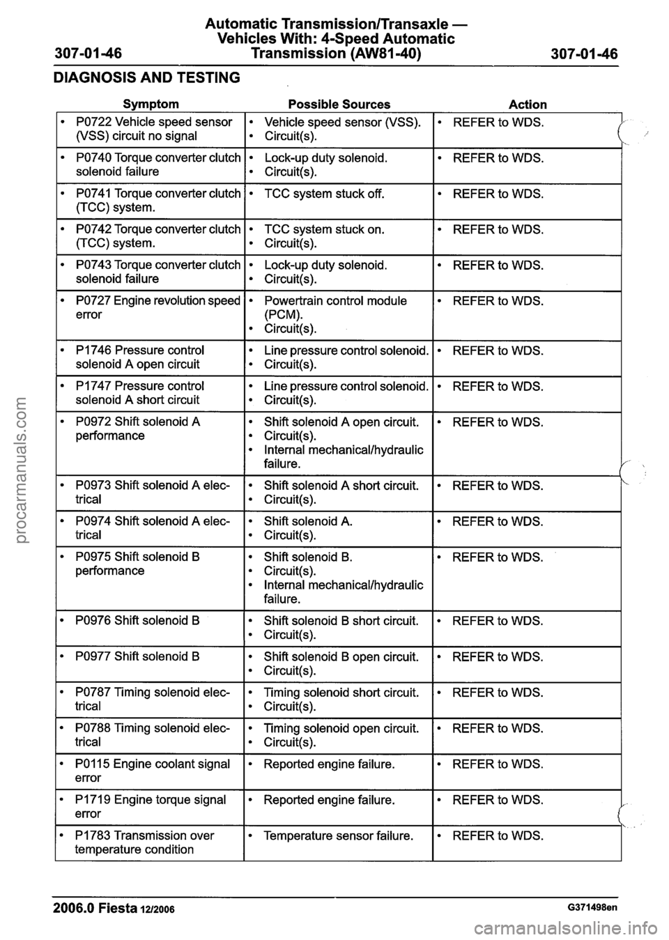
Symptom Possible Sources Action
PO722 Vehicle speed sensor Vehicle speed sensor (VSS).
1 (vSS) circuit no signal I circuit(+
REFER to WDS.
PO740 Torque converter clutch Lock-up duty solenoid.
solenoid failure
I ~ircuit(s).
REFER to WDS.
REFER to WDS.
PO741 Torque converter clutch
1 (TCC) system.
PO742 Torque converter clutch TCC system stuck on.
I circuit(s).
TCC system stuck off.
REFER to WDS.
PO743 Torque converter clutch Lock-up duty solenoid.
solenoid failure
I circuit(s).
REFER to WDS.
REFER to WDS.
PO727 Engine revolution speed
error
PI 746 Pressure control
I solenoid A open circuit
Powertrain control module
(PCM).
Circuit(s).
I
Line pressure control solenoid.
Circuit(s).
REFER to WDS.
PI 747 Pressure control
solenoid
A short circuit
Line pressure control solenoid.
Circuit(s).
REFER to WDS.
PO972 Shift solenoid A
performance Shift solenoid
A open
circuit.
Circuit(s).
Internal mechanical/hydraulic
failure.
REFER to WDS.
REFER to WDS.
PO974 Shift solenoid A elec- Shift solenoid A.
trical I circuit(!+
PO973 Shift solenoid A elec-
trical
REFER to WDS. Shift solenoid A short circuit.
Circuit(s).
PO975 Shift solenoid B
performance Shift solenoid
B.
Circuit(s).
Internal mechanical/hydraulic
failure.
REFER
to WDS.
PO976 Shift solenoid B Shift solenoid B short circuit.
Circuit(s).
REFER to WDS.
PO977 Shift solenoid B Shift solenoid B open circuit.
Circuit(s).
REFER to WDS.
PO787 Timing solenoid elec- Timing solenoid short circuit.
trical I circuit(s).
REFER to WDS.
REFER to WDS. PO788 Timing solenoid elec-
trical
-- - -
Timing solenoid open circuit.
Circuit(s).
REFER to WDS. PO1 15 Engine coolant signal
error Reported engine failure.
REFER to WDS. I PI 71 9 Engine torque signal
error Reported engine failure.
REFER to WDS. PI 783 Transmission over
temperature condition
2006.0 Fiesta 12/2006 G371498en
Temperature sensor failure.
procarmanuals.com
Page 1007 of 1226
Automatic Transmission/Transaxle -
Vehicles With: 4-Speed Automatic
307-01 47 Transmission (AW81-40) 307-01 -47
DIAGNOSIS AND TESTING
Symptom Possible Sources Action
'
U2516 CAN bus off transmit
error
I 5750 Throttle open malfunction 1 . CAN bus. 1. REFER to WDS. I
CAN bus.
U1900 CAN Communication
bus fault error
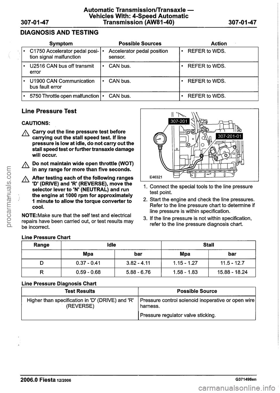
Line Pressure Test
C1750 Accelerator pedal posi-
tion signal malfunction
. CAN bus.
CAUTIONS:
A Carry out the line pressure test before
carrying out the stall speed test.
If line
pressure is low at idle, do not carry out the
stall speed test or further transaxle damage
will occur.
Accelerator pedal position
sensor.
A Do not maintain wide open throttle (WOT)
in any range for more than five seconds.
REFER to WDS.
A After testing each of the following ranges
ID' (DRIVE) and 'R' (REVERSE)r move the 1. Connect the special tools to the line pressure selector lever to 'N' (NEUTRAL) and run
the engine at
I000 rpm for approximately test point.
i, 1 minute to allow the torque converter to 2. Start the engine and check the line pressures.
cool. Refer to the line pressure chart to determine if -- --- line pressure is within specification. N0TE:Make sure that the self test and electrical 3m If the line pressure is not within specification, repairs have been carried out, or test results may
be incorrect. refer to the
line pressure diagnosis chart.
Line Pressure Chart
Range
Idle Stall
R 0.59 - 0.68 5.88 - 6.76 1.58 - 1.83 15.88 - 18.24
Line Pressure Diagnosis Chart
I I Pressure regulator valve sticking. I
Test Results
Higher than specification in 'D' (DRIVE) and 'R'
(REVERSE)
2006.0 Fiesta 1212006 G371498en
Possible Source
Pressure control solenoid inoperative or open wire
harness.
procarmanuals.com
Page 1008 of 1226
Automatic TransmissionlTransaxle -
Vehicles With: 4-Speed Automatic
307-01 -48 Transmission (AW81-40) 307-01 -48
DIAGNOSIS AND TESTING
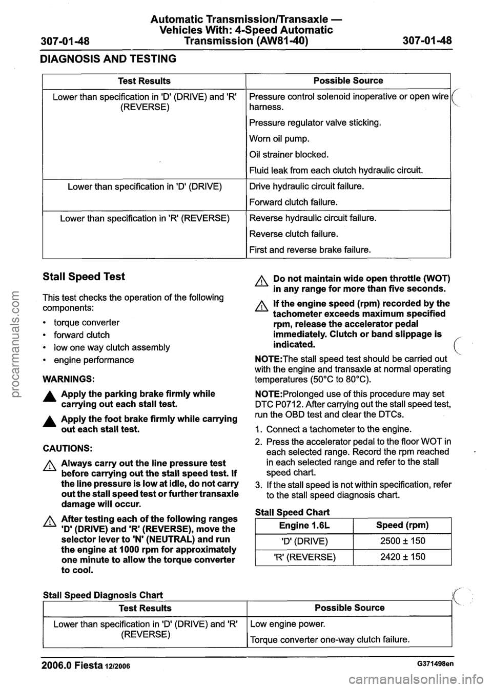
Stall Speed Test
This test checks the operation of the following
components:
1
Test Results
Lower than specification in 'Dl (DRIVE) and 'R'
(REVERSE)
Lower than specification in
'Dl (DRIVE)
Lower than specification in
'R' (REVERSE)
torque converter
forward clutch
low one way clutch assembly
engine performance
Possible Source
Pressure control solenoid inoperative or open wire
harness.
Pressure regulator valve sticking.
Worn oil pump.
Oil strainer blocked.
Fluid leak from each clutch hydraulic circuit.
Drive hydraulic circuit failure.
Forward clutch failure.
Reverse hydraulic circuit failure. Reverse clutch failure.
First and reverse brake failure.
WARNINGS:
A Do not maintain wide open throttle (WOT)
in any range for more than five seconds.
A If the engine speed (rpm) recorded by the
tachometer exceeds maximum specified
rpm, release the accelerator pedal
immediately. Clutch or band slippage is
indicated.
N0TE:The stall speed test should be carried out
with the engine and transaxle at normal operating
temperatures (50°C to 80°C).
A Apply the parking brake firmly while N0TE:Prolonged use of this procedure may set
carrying out each stall test. DTC PO71 2. After carrying out the stall speed test,
A Apply the foot brake firmly while carrying run the OBD test and clear the DTCs.
out each stall test. I. Connect a tachometer to the engine.
CAUTIONS:
A Always carry out the line pressure test
before carrying out the stall speed test. If
the line pressure is low at idle, do not carry
out the stall speed test or further transaxle
damage will occur.
A After testing each of the following ranges
'D'
(DRIVE) and 'R' (REVERSE), move the
selector lever to
'N' (NEUTRAL) and run
the engine at 1000 rpm for approximately
one minute to allow the torque converter
to cool.
2. Press the accelerator pedal to the floor WOT in
each selected range. Record the rpm reached
in each selected range and refer to the stall
speed chart.
3. If the stall speed is not within specification, refer
to the stall speed diagnosis chart.
Stall S~eed Chart
I Engine 1.6L I Speed (rpm) I
I 'Dl (DRIVE) I 2500 2 150 1
'R' (REVERSE) 2420 +, 150 -
Stall
Speed Diagnosis Chart
2006.0 Fiesta 1212006 G371498en
Test Results
Lower than specification in ID' (DRIVE) and 'R'
(REVERSE)
Possible Source
Low engine power.
Torque converter one-way clutch failure.
procarmanuals.com