2007 FORD FIESTA low oil pressure
[x] Cancel search: low oil pressurePage 829 of 1226

Fuel Charging and Controls - 2.OL
303-04B-21 Duratec-HE (M14) 303-04B-21
DIAGNOSIS AND TESTING
Symptom
Engine knock at idle
Possible Sources Action
Fuel injectors.
INSPECT the fuel injectors.
CLEAN the fuel injectors or
INSTALL a new set of injectors
as required only after the
checks have been carried out.
Fuel rail fuel pressure sensor.
Carry out a full engine
diagnosis using the guided
diagnostic menu in WDS.
Low cylinder compression.
CHECK the engine compres-
sion.
Worn or damaged
valve(s),
tappet(s) or camshaft(s).
REMOVE the cylinder head.
INSPECT the cylinder head,
valves, tappets and camshafts
for signs of wear or damage.
REFER to: Cylinder Head (303-
01 C, In-vehicle Repair).
Damaged cylinder head gasket. REMOVE the cylinder head.
INSPECT the cylinder head
gasket and cylinder bores for
wear or damage.
REFER to: Cylinder Head (303-
01 C, In-vehicle Repair).
Low engine oil level.
CHECK the engine oil level.
REFILL as necessary.
Incorrect or contaminated fuel.
-
KS. CHECK
for signs of contamina-
tion such as strange odors from
the fuel tank.
If contaminated fuel is found,
DRAIN the complete fuel
system. FLUSH the fuel system
through with clean gasoline.
REFER to: Fuel Tank Draining
(31
0-OOA, General Proced-
u res).
INSTALL a new fuel filter.
INSPECT the fuel injectors.
CLEAN the fuel injectors or
INSTALL a new set of injectors
as required only after the
checks have been carried out. INSTALL a new fuel rail.
REFER to: Fuel Injection
Supply Manifold
(303-04C,
Removal and Installation).
Carry out a full engine
diagnosis using the guided
diagnostic menu in WDS.
2006.0 Fiesta 1212006 GI 65371 en
procarmanuals.com
Page 831 of 1226

Fuel Charging and Controls - 2.OL
303-048-23 Duratec-HE (M14) 303-04B-23
DIAGNOSIS AND TESTING
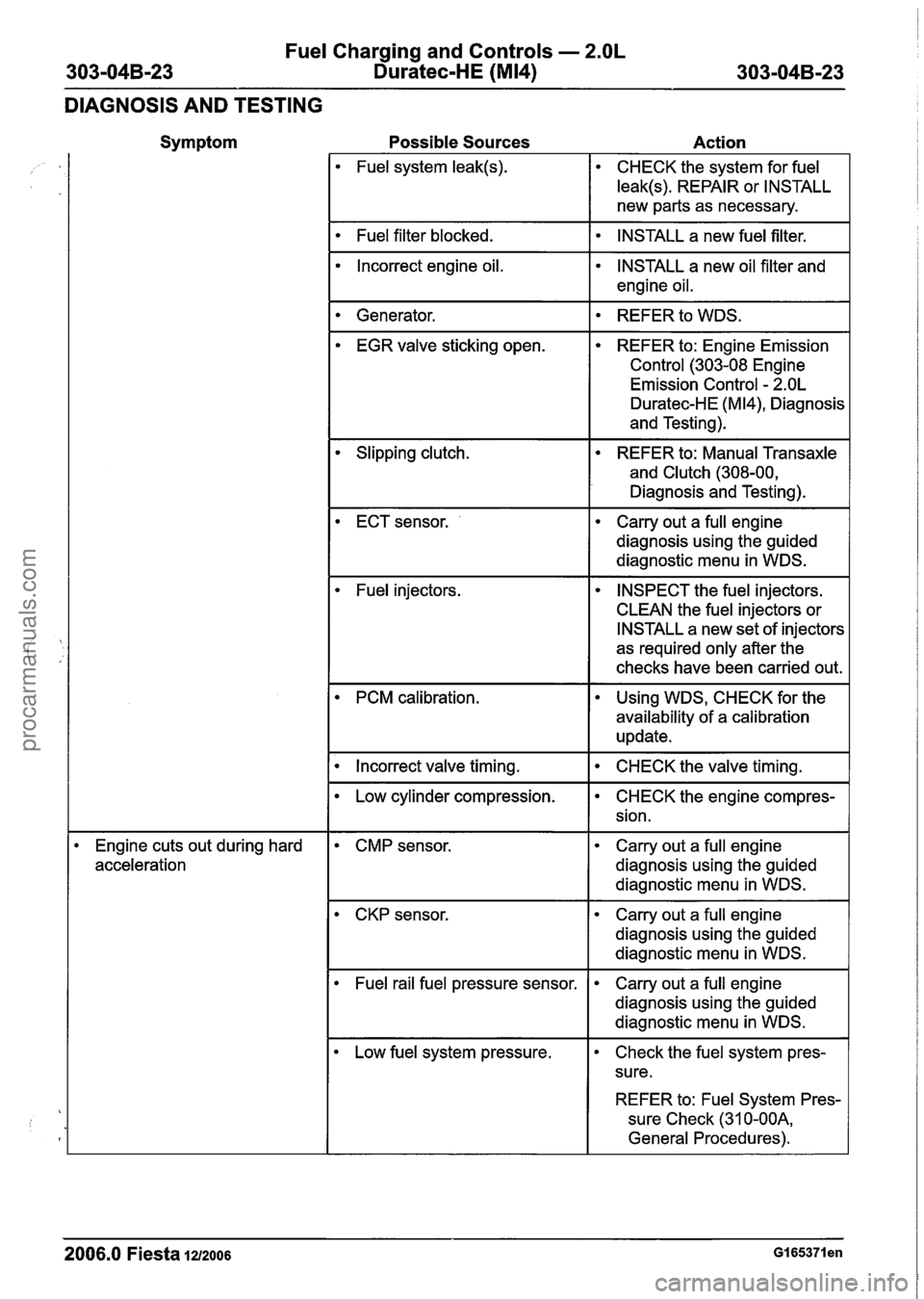
Symptom
Possible Sources Action
Fuel system leak(s). CHECK the system for fuel
leak(s). REPAIR or INSTALL
new parts as necessary.
I Fuel filter blocked. I INSTALL a new fuel filter. I
Incorrect engine oil.
INSTALL a new oil filter and
engine oil.
I Generator. 1. REFER to WDS. I
EGR valve sticking open. REFER to: Engine Emission
Control (303-08 Engine
Emission Control
- 2.OL
Duratec-HE (M 14), Diagnosis
and Testing).
Slipping
clutch. REFER to: Manual Transaxle
and Clutch (308-00,
Diagnosis and Testing).
ECT sensor.
--
Carry out a full engine
diagnosis using the guided
diagnostic menu in WDS.
Fuel injectors. INSPECT the fuel injectors.
CLEAN the fuel injectors or
INSTALL a new set of injectors
as required only after the
checks have been carried out.
PCM calibration. Using WDS, CHECK for the
availability of a calibration
update.
--
I . Incorrect valve timing. I CHECK the valve timing. I
Engine cuts out during hard
acceleration
Low cylinder compression.
CMP sensor. CHECK
the engine compres-
sion.
Carry out a full engine
diagnosis using the guided
diagnostic menu in WDS.
CKP sensor. Carry out a full engine
diagnosis using the guided
diagnostic menu in WDS.
Fuel rail fuel pressure sensor.
REFER to: Fuel System Pres-
sure Check (31
0-OOA,
General Procedures).
Carry out a full engine
diagnosis using the guided
diagnostic menu in WDS.
Low fuel system pressure.
2006.0 Fiesta 1212006 GI 65371 en
Check the fuel system pres-
sure.
procarmanuals.com
Page 835 of 1226

Fuel Charging and Controls - 2.OL
303-04B-27 Duratec-HE (M14) 303-04B-27
REMOVAL AND INSTALLATION
Fuel Rail
Materials Name Specification
I Engine Oil - 5W-30 I WSS-~2~91 3-B I
WARNINGS:
A Do not smoke or carry lighted tobacco or
open flame of any type when working on
or near any fuel related components.
Highly flammable vapors are always
present and may ignite. Failure to follow
these instructions may result in personal
injury.
A This procedure involves fuel handling. Be
prepared for fuel spillage at all times and
always observe fuel handling precautions.
Failure to follow these instructions may
result in personal injury.
1. Release the fuel system pressure.
For additional information, refer to: Fuel
System Pressure Release (31 0-00 Fuel
System
- General Information, General
Procedures).
2. Disconnect the battery ground cable.
For additional information, refer to: Battery
Disconnect
(414-01 Battery, Mounting and
Cables, General Procedures).
3. Remove the air cleaner assembly.
For additional information, refer to: Air
Cleaner
- 2.OL Duratec-HE (M14) (303-1 2
intake Air Distribution and Filtering,
Removal and Installation).
4. Remove the components in the order
indicated in the following
illustration(s) and
table(s).
Item Description Item Description
Fuel charging wiring harness retaining clip
See Removal Detail
Fuel charging wiring harness electrical
connector
2006.0 Fiesta 1212006 G421322en
procarmanuals.com
Page 939 of 1226

303-1 4-1 5 Electronic Engine Controls 303-1 4-1 5
DIAGNOSIS AND TESTING
Monitors
The purpose of the monitors is to continuously
check the operation of the emission related sensors
and actuators. It then establishes if they are
operating within specified tolerances. All monitors
carry out their functions in such a way as to be
unnoticeable by the driver of the vehicle. Each one
is carried out under specific conditions of load,
speed and engine temperature. The Comprehensive Component Monitor, Combustion
Misfire Monitor and
AirIFuel Ratio Monitor operate
continuously. The remaining monitors are only
invoked under certain operating conditions. On
diesel variants, all of the monitors operate under
normal driving conditions: There are no monitors
which intervene and cause special operating
modes to enable the monitors to work. Some diesel
monitors are non-continuous. This means that in
a drive cycle, monitoring is done as and when
suitable driving conditions exist and potential faults
are accumulated and compared with acceptance
criteria. Examples of this type are the turbocharger
boost pressure and exhaust gas recirculation
(EGR) monitors on vehicles with common rail fuel
injection.
( Comprehensive Component Monitor (CCM)
When the CCM detects a component operating out
of tolerance, it sets a Diagnostic Trouble Code
(DTC), which is stored in the EEPROM. If the same
concern is confirmed during the next trip the MIL
will be switched on. The CCM monitors many
components, sub-systems and signals. The
following is a list of those that can effect emissions
depending on application:
Electronic Ignition (El) System.
Crankshaft Position (CKP) Sensor.
Ignition Coil.
Electronic Throttle Control Unit.
Camshaft Position (CMP) Sensor.
Air Conditioning
(AIC) Clutch.
Idle Air Control (IAC) Valve.
Mass Air Flow (MAF) Sensor.
Manifold Absolute Pressure (MAP) Sensor.
Intake Air Temperature (IAT) Sensor.
Engine Coolant Temperature (ECT) Sensor.
Cylinder Head Temperature (CHT) Sensor.
Heated Oxygen Sensor
(H02S).
Catalyst Monitor Sensor.
Charge Air Temperature Sensor.
Knock Sensor (KS).
Throttle Position (TP) Sensor.
Vehicle Speed Sensor (VSS).
Boost Pressure Sensor.
Cam-Crank Phasing Sensor.
EEPROM.
High Pressure Fuel Injection Pump.
Exhaust Gas Recirculation (EGR) Valve Monitor.
Fuel Injectors.
Turbocharger.
Combustion Noise Monitor.
Barometric Pressure (BARO) Sensor.
Combustion Misfire Monitor (All except vehicles
with diesel engine)
The combustion misfire monitor operates independently of the others, and can detect misfires
caused by the ignition system, fuel system or
mechanical engine components. As each cylinder
fires, a characteristic crankshaft acceleration is
produced. The monitor detects irregularities in the
acceleration pattern using the crankshaft position (CKP) sensor, thus detecting the misfire. It can
also detect which cylinder has misfired.
Combustion misfires can be categorized as follows:
Type
A: These can cause catalytic converter
damage due to excessive internal temperatures.
If a certain number of misfires occur over a
pre-determined number of engine revolutions, the
MIL will be switched on to alert the driver of the
concern.
Type B: These can lead to an increase in emissions
to a point above the EOBD threshold. If the misfire
is detected during a second trip, over a,
pre-determined number of engine revolutions, the
MIL will be switched on. If the misfire does not
occur over the next three trips, the MIL will be
extinguished
AirIFuel Ratio (AFR) Monitor (All except vehicles
with diesel engine)
The H02S fitted before the catalytic converter
(upstream) measures the oxygen content of the
exhaust gas and the variations in it. This then
enables the PCM to adjust the opening times of
the fuel injectors to maintain the correct AFR. This
is known as Short Term Fuel Trim (STFT). If the
same variation is registered a pre-determined
number of times, a permanent correction factor is
applied. This is known as Long Term Fuel Trim
(LTFT), which is stored in the EEPROM. When the
correction factors exceed pre-determined limits a
DTC will be set in the EEPROM. If a concern is
2006.0 Fiesta 1212006 G384566en
procarmanuals.com
Page 1008 of 1226

Automatic TransmissionlTransaxle -
Vehicles With: 4-Speed Automatic
307-01 -48 Transmission (AW81-40) 307-01 -48
DIAGNOSIS AND TESTING
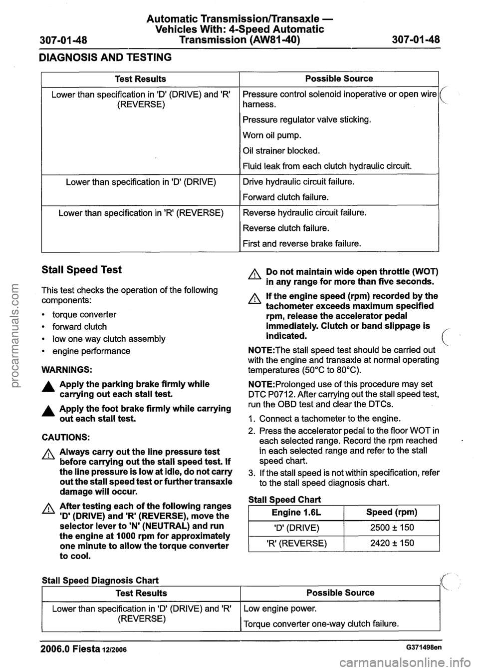
Stall Speed Test
This test checks the operation of the following
components:
1
Test Results
Lower than specification in 'Dl (DRIVE) and 'R'
(REVERSE)
Lower than specification in
'Dl (DRIVE)
Lower than specification in
'R' (REVERSE)
torque converter
forward clutch
low one way clutch assembly
engine performance
Possible Source
Pressure control solenoid inoperative or open wire
harness.
Pressure regulator valve sticking.
Worn oil pump.
Oil strainer blocked.
Fluid leak from each clutch hydraulic circuit.
Drive hydraulic circuit failure.
Forward clutch failure.
Reverse hydraulic circuit failure. Reverse clutch failure.
First and reverse brake failure.
WARNINGS:
A Do not maintain wide open throttle (WOT)
in any range for more than five seconds.
A If the engine speed (rpm) recorded by the
tachometer exceeds maximum specified
rpm, release the accelerator pedal
immediately. Clutch or band slippage is
indicated.
N0TE:The stall speed test should be carried out
with the engine and transaxle at normal operating
temperatures (50°C to 80°C).
A Apply the parking brake firmly while N0TE:Prolonged use of this procedure may set
carrying out each stall test. DTC PO71 2. After carrying out the stall speed test,
A Apply the foot brake firmly while carrying run the OBD test and clear the DTCs.
out each stall test. I. Connect a tachometer to the engine.
CAUTIONS:
A Always carry out the line pressure test
before carrying out the stall speed test. If
the line pressure is low at idle, do not carry
out the stall speed test or further transaxle
damage will occur.
A After testing each of the following ranges
'D'
(DRIVE) and 'R' (REVERSE), move the
selector lever to
'N' (NEUTRAL) and run
the engine at 1000 rpm for approximately
one minute to allow the torque converter
to cool.
2. Press the accelerator pedal to the floor WOT in
each selected range. Record the rpm reached
in each selected range and refer to the stall
speed chart.
3. If the stall speed is not within specification, refer
to the stall speed diagnosis chart.
Stall S~eed Chart
I Engine 1.6L I Speed (rpm) I
I 'Dl (DRIVE) I 2500 2 150 1
'R' (REVERSE) 2420 +, 150 -
Stall
Speed Diagnosis Chart
2006.0 Fiesta 1212006 G371498en
Test Results
Lower than specification in ID' (DRIVE) and 'R'
(REVERSE)
Possible Source
Low engine power.
Torque converter one-way clutch failure.
procarmanuals.com
Page 1009 of 1226

Automatic Transmission/Transaxle -
Vehicles With: 4-Speed Automatic
307-01 49 Transmission (AW81-40) 307-01 -49
DIAGNOSIS AND TESTING
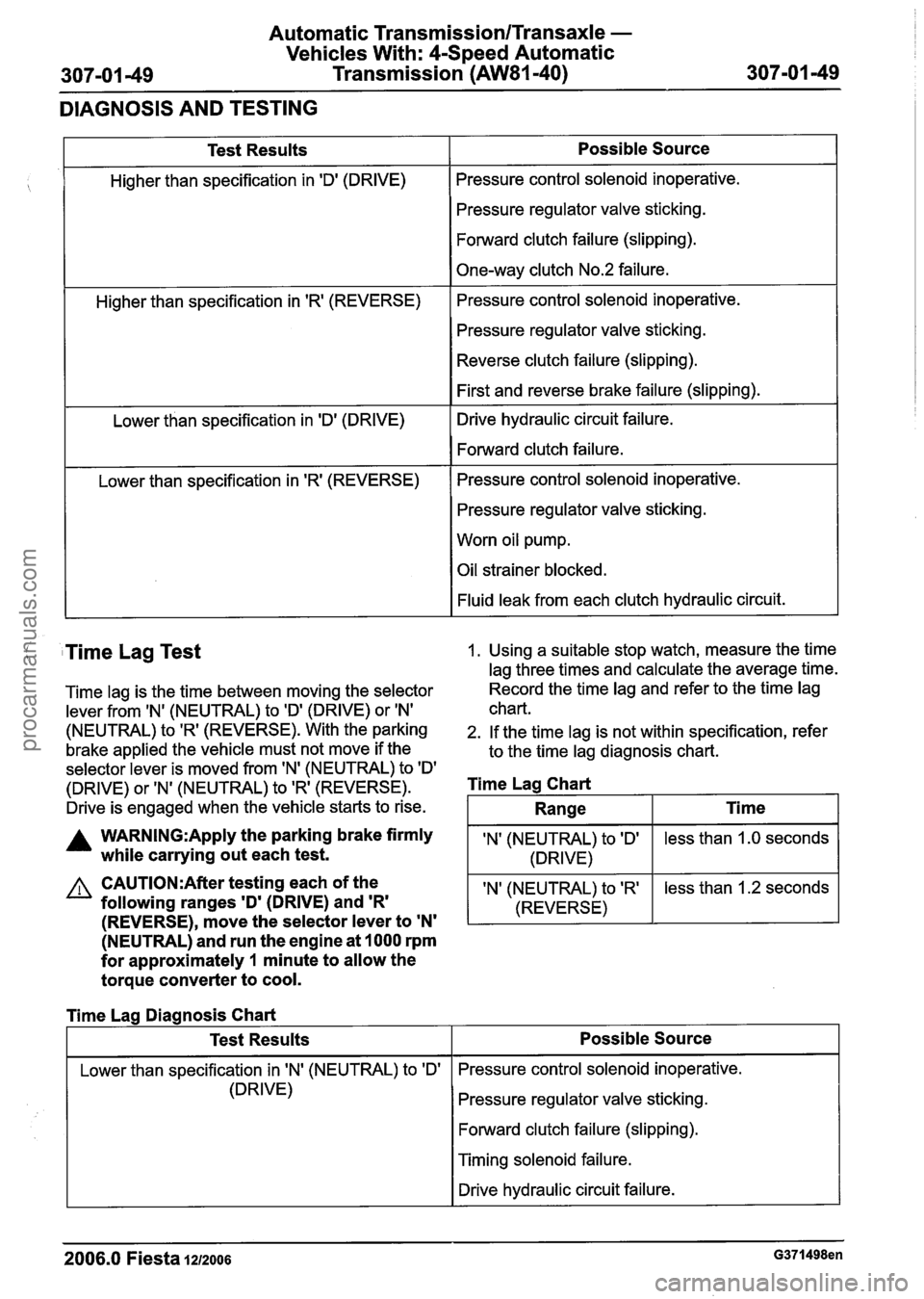
Test Results
Higher than specification in 'Dl (DRIVE)
Higher than specification in
'R' (REVERSE)
Lower than specification in 'D' (DRIVE)
Lower than specification in
'R' (REVERSE)
Possible Source
Pressure control solenoid inoperative.
Pressure regulator valve sticking.
Forward clutch failure (slipping).
One-way clutch No.2 failure.
Pressure control solenoid inoperative.
Pressure regulator valve sticking.
Reverse clutch failure (slipping).
First and reverse brake failure (slipping).
Drive hydraulic circuit failure.
Forward clutch failure.
Pressure control solenoid inoperative.
Pressure regulator valve sticking.
Worn oil pump.
Oil strainer blocked.
Fluid leak from each clutch hydraulic circuit.
( Time Lag Test 1. Using a suitable stop watch, measure the time
lag three times and calculate the average time.
Time lag is the time between moving the selector Record the
time lag and refer to the time lag
lever from
IN' (NEUTRAL) to ID' (DRIVE) or IN' chart.
(NEUTRAL) to 'R' (REVERSE). With the parking 2. If the time lag is not within specification, refer
brake applied the vehicle must not move if the
to the time lag diagnosis chart.
selector lever is moved from 'N' (NEUTRAL) to
ID'
(DRIVE) or 'N' (NEUTRAL) to 'R' (REVERSE). Time Lag Chart
Drive is engaged when the vehicle starts to rise.
A WARN1NG:Apply the parking brake firmly IN' (NEUTRAL) to ID' while carrying out each test. 1 (DRIVE)
(NEUTRAL) and run the engine at 1000 rpm
for approximately
1 minute to allow the
torque converter to cool.
less than 1.0 seconds
CAUTI0N:After testing each of the
following ranges
'D' (DRIVE) and 'R'
Range
I Lower than specification in IN' (NEUTRAL) to 'Dl I Pressure control solenoid inoperative.
Ti me
(REVERSE), move the selector lever to 'N'
'N' (NEUTRAL) to 'R'
(REVERSE)
Time Lag Diagnosis Chart
(DRIVE) less
than 1.2 seconds
Test Results
Pressure regulator valve sticking.
Forward clutch failure (slipping).
Possible Source
I Timing solenoid failure.
I I Drive hydraulic circuit failure. I
2006.0 Fiesta IZIZOO~ G371498en
procarmanuals.com
Page 1061 of 1226

Manual Transmission/Transaxle and Clutch -
308-00-3 General Information 308-00-3
DIAGNOSIS AND TESTING
Manual Transaxle and Clutch
lnspection and Verification
General Equipment selected with the engine running and the parking
brake applied, without any concerns, the clutch
2. If the gear@) cannot be selected, REFER to
Symptom Chart.
Ultraviolet
fluid leak detection equipment
1. Verify the customer concern.
Transaxle noise concerns
2. Visually inspect for obvious signs of mechanical is
OK.
damage. 1. Check the engine and transaxle support for
Oil leaks.
Visibly damaged or worn components.
Visual lnspection Chart insufficient gap between the transaxle and the
body.
REFER to:
RoadlRoller Testing (1 00-00 General
Information, Description and Operation).
Mechanical 2. Road test the vehicle.
4. If the cause is not evident, verify the symptom
and REFER to Symptom Chart.
Oil leakage concerns
Loose or missing nuts or bolts.
( I The following checks should be carried out before
repairing or installing a new transaxle. 1.
Check the transaxle fluid level. If necessary,
3. If a noise occurs in various gears at the same
- - drain off any excess fluid.
The inspection and verification of manual transaxle
concerns can be considered in three main areas. 2. Clean the transaxle and the adjacent areas
carefully and road test the vehicle.
engine speed,
check if the noise also occurs in
3. If an obvious cause for an observed or reported the neutral position.
If it does, the noise is not
concern is found, correct the cause (if possible) caused
by the transaxle.
before proceeding to the next step. 4.
REFER to Symptom Chart.
Gear shifting concerns REFER to: RoadlRoller Testing (1 00-00 General
Information, Description and Operation).
1, Check the operation of the clutch: Lay a block 3. U~ing suitable ultraviolet fluid leak detection
of wood approximately
25 mm thick under the equipment, locate
the leak and check whether
clutch pedal and depress the clutch pedal as the leaking fluid
is transaxle fluid, brake fluid
far as the stop. If first or second gear can be (from the hydraulically operated clutch)
or
engine oil.
4. REFER to Symptom Chart.
Symptom Chart
Symptom Possible Sources Action
I
Clutch slippage Clutch master
cylinder.
Clutch slave cylinder.
Clutch pressure plate.
Clutch disc.
Engine or transaxle housing oil
or fluid
leak@).
GO to Pinpoint Test A.
Clutch chatter or shudder Engine and transaxle
mounts. REFER to:
Noise, Vibration and
Harshness (NVH) (1 00-04,
Diagnosis and Testing).
Clutch pressure plate.
Clutch disc.
Flywheel.
--
GO to Pinpoint Test B.
- -
2006.0 Fiesta 1212006 G25629en
procarmanuals.com
Page 1066 of 1226

Manual Transmission/Transaxle and Clutch -
General Information
DIAGNOSIS AND TESTING
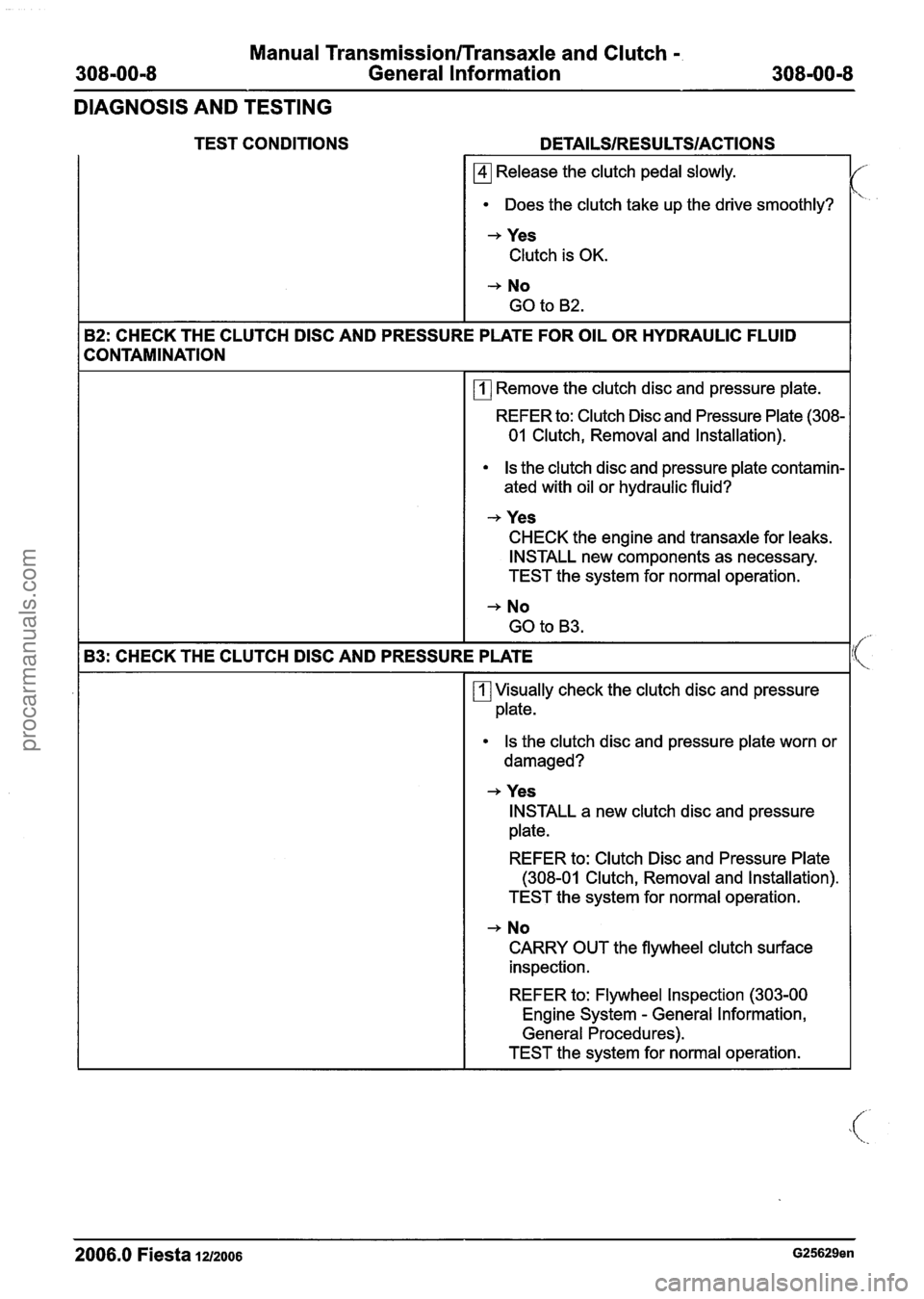
TEST CONDITIONS
Release the clutch pedal slowly.
Does the clutch take up the drive smoothly?
-+ Yes
Clutch is OK.
-+ No
GO to
B2.
B2: CHECK THE CLUTCH DlSC AND PRESSURE PLATE FOR OIL OR HYDRAULIC FLUID
CONTAMINATION
rn Remove the clutch disc and pressure plate.
REFER to: Clutch Disc and Pressure Plate (308-
01 Clutch, Removal and Installation).
Is the clutch disc and pressure plate contamin-
ated with oil or hydraulic fluid?
-+ Yes
CHECK the engine and transaxle for leaks.
INSTALL new components as necessary.
TEST the system for normal operation.
-+ No
GO to B3.
B3: CHECK THE CLUTCH
DlSC AND PRESSURE PLATE
rn Visually check the clutch disc and pressure
plate.
Is the clutch disc and pressure plate worn or
damaged?
-+ Yes INSTALL a new clutch disc and pressure
plate.
REFER to: Clutch Disc and Pressure Plate
(308-01 Clutch, Removal and Installation).
TEST the system for normal operation.
-+ No
CARRY OUT the flywheel clutch surface
inspection.
REFER to: Flywheel Inspection (303-00
Engine System
- General Information,
General Procedures).
TEST the system for normal operation.
2006.0 Fiesta 12/2006 G25629en
procarmanuals.com