2007 FORD FIESTA key battery
[x] Cancel search: key batteryPage 35 of 1226

100-00-1 9 General Information 100-00-1 9
DESCRIPTION AND OPERATION
Standard Workshop Practices
Vehicle in Workshop
When working on a vehicle in the workshop always
make sure that:
- the parking brake is applied or the wheels are
securely chocked to prevent the vehicle moving
forwards or backwards.
- the key is removed from key operated hood
locks before any work is carried out around the
front of the vehicle.
- if the engine is to be run, there is adequate
ventilation, or an extraction hose to remove
exhaust fumes.
- there is adequate room to raise the vehicle and
remove the wheels, if necessary.
- fender covers are always fitted if any work is to
be carried out in the engine compartment.
- the battery is disconnected if working on the
engine, underneath the vehicle, or if the vehicle
is raised.
Alternative Fuel - Dons
- Do work on the vehicle in a designated area,
that is well ventilated and with access restricted
to qualified personnel only.
- Install new warning labels to their original
locations.
- If possible always isolate the alternative fuel
tank, and run the vehicle on the alternative fuel
until it automatically switches to its normal fuel
prior to taking the vehicle into the workshop
service area.
- Only use tested and approved components and
pipes when repairing or servicing
LPG and CNG
systems.
Alternative Fuel - Do Nots
- Do not vent off LPG fuel.
- Do not use shop air pressure to force LPG fuel
from the fuel tank.
( A CAUTION:When electric arc welding on a - Do not use paint drying ovens above 40°C for vehicle, always disconnect the generator any alternative fuel vehicle. LPG and CNG fuel wiring to prevent the possibility of a surge tanks must be removed from the vehicle prior of current causing damage to the internal to being put into paint drying ovens above 40°C. components of the generator. - Do not modify the system or install new - if using welding equipment on the vehicle, a
components that are not designed for gas
suitable fire extinguisher is readily available.
vehicles.
Alternative Fuel
A WARNING:When servicing the fuel system
always follow the recommended
procedures. Failure to follow these
instructions may result in personal injury.
If the odor of liquefied petroleum gas (LPG) or
compressed natural gas
(CNG) is present in the
air in the workshop, warn all persons in the area
to:
- extinguish all flames and lighted tobacco.
- shut off electrical and air powered equipment.
- evacuate the area.
- ventilate the area.
- contact the fire control authorities.
- remove the vehicle to a dedicated, ventilated
area.
- Do not evacuate fuel tanks unless there is repair
that requires the removal of the fuel tank.
- Do not work on the fuel lines or system
components unless the alternative fuel has been
evacuated and the pressure in the system
reduced to atmospheric or less.
- Do not use anything other than the specified
leak detector fluid to trace fuel leaks.
Be aware of situations that may cause the
LPG or I
CNG fuel system to vent off fuel, such as: I
- extremely hot days.
- parking by a space heater.
- hoisting a vehicle up near a ceiling heater.
Only fully trained personnel, who are conversant
with local standards, are to work on alternative fuel
vehicles.
2006.0 Fiesta 1212006 GI 7373en
procarmanuals.com
Page 867 of 1226

303-06-3 Starting System 303-06-3
DESCRIPTION AND OPERATION
Starting System
Starting system
1 tern Description
I 1 I lgnitionlstarter switch I
1 2 1 Starter relay I
1 3 1 Electric starter motor I
1 4 1 Powertrain control module (PCM) I
1 5 1 Sensor,- crankshaft position ( CKP) I
The purpose of the starting system is to turn the
engine crankshaft at a speed which enables the
engine to start.
The engine is started as follows:
Ignitionlstarter switch in position
Ill.
The starter relay is activated by the PCM .
The solenoid is supplied with voltage.
The solenoid engages the starter motor pinion
with the flywheel ring gear.
The solenoid applies battery current to the
starter.
The starter turns the crankshaft until the engine
starts. The key can then be released and it
automatically returns to position
I I.
The system incorporates the "Smart
StartingWstrategy. This makes starting faster and
protects the starter.
If the driver fails to release the key immediately
after the engine starts, the PCM interrupts
activation of the starter relay and thus switches off
the electric starter motor.
The speed signal provided by the CKP sensor is
used for monitoring the starting procedure.
2006.0 Fiesta 1212006 GI 63308en
procarmanuals.com
Page 930 of 1226

303-1 4-6 Electronic Engine Controls 303-1 4-6
DESCRIPTION
AND OPERATION
Item Descri~tion
1 5 1 Crankshaft Position (CKP) sensor 1
Throttle Control Unit (TCU)
1 6 ( Camshaft Position (CMP) sensor I Components
1 7 1 Heated Oxygen Sensor (H02S) I
1 8 1 Power Steering Pressure (PSP) sensor I
1 10 1 Brake Pedal Position (BPP) switch I
9 Vehicle Speed Sensor (VSS)
(only on
vehicles without Anti-lock Braking System
(ABS))
1 12 1 Clutch Pedal Position (CPP) switch I
11
1 13 1 Generator I
Accelerator Pedal Position (APP) sensor
1 14 1 Current supply relay I
1 15 1 Ignition key I -
16
17
1 20 1 Inertia fuel shut-off switch I
Battery
Powertrain Control Module (PCM)
-
18
19
1 21 1 Fuel Pump Driver Module (FPDM) I
Data Link Connector (DLC)
Fuel Pump (FP) relay
1 22 1 Fuel injectors I
23 Evaporative emissions (EVAP) solenoid
1 lvalve
1 24 1 Idle Air Control (IAC) valve 1
1 25 1 Throttle Control Unit (TCU) I
26 Air Conditioning (AIC) compressor clutch
1 I 1 blower switch
1 27 1 Injector Driver
Module (IDM) I
1 28 1 Start inhibit relay I
1 29 1 Instrument cluster I
Item Descri~tion
I I ITP sensor I
1 2 1 Electric motor I
The electronically controlled throttle control unit
(TCU) consists of the following components:
Housing
Throttle flap
Throttle flap spindle
Gear set
Electric motor with pinion
TP sensor
Stop screw
Throttle flap return spring
2006.0 Fiesta 1212006 G204204en
procarmanuals.com
Page 947 of 1226

303-1 4-23 Electronic Engine Controls 303-1 4-23
REMOVAL AND INSTALLATION
7. Remove the remains of the shear bolt from 4.
If a new PCM is being installed connect WDS.
/ the PCM using grips. Download the PCM configuration information
using the programmable modules installation
routine.
5. N0TE:Do not press the accelerator pedal
during the initialization period as this will
prevent the complete initialization of the
throttle body.
Turn the ignition key to position
I1 and wait
for one minute to initialize the throttle body.
6. Turn the ignition key to the OFF position.
Installation
I. Install a new shear bolt and securing clip,
using the special tool to push the clip onto
the shank of the bolt.
2. Install the PCM electrical connector to the
PCM.
Tighten the bolt until the head shears off.
3. Install the battery tray.
For additional information, refer to: Battery
Tray
(414-01, Removal and Installation).
procarmanuals.com
Page 1025 of 1226

Automatic Transmission/Transaxle -
Vehicles With: 4-Speed Automatic
Transmission (AW81-40)
REMOVAL AND INSTALLATION
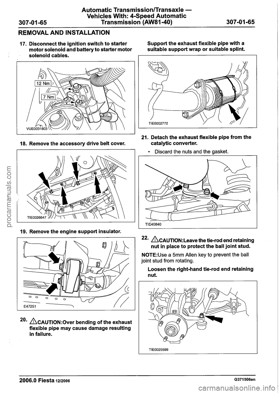
17. Disconnect the ignition switch to starter Support
the exhaust flexible pipe with a
motor solenoid and battery to starter motor suitable
support wrap or suitable splint.
solenoid cables.
21. Detach the exhaust flexible pipe from the
18. Remove the accessory drive belt cover. catalytic
converter.
Discard the nuts and the gasket.
19. Remove the engine support insulator.
22m &AUTION:L~~~~ the tie-rod end retaining
nut in place to protect the ball joint stud.
N0TE:Use a 5mm Allen key to prevent the ball
joint stud from rotating.
20m ACAUTION:~~~~ bending of the exhaust
flexible pipe may cause damage resulting
in failure. Loosen
the right-hand tie-rod end retaining
nut.
2006.0 Fiesta 1212006 G371506en
procarmanuals.com
Page 1219 of 1226

Acceleration Control - 1.3L Duratec-8V
(Rocam)ll.25L Duratec-1 6V (Sigma)ll.4L
31 0-02A-5 Duratec-1 6V (Sigma)/l .6L Duratec-1 6V (Sigma)
31 0-02A-5
DIAGNOSIS AND TESTING
PCM to the electronic throttle body including
the electrical connectors in area "B" (see
system overview).
- There is an obstruction inside the throttle
body bore. Remove the air cleaner outlet pipe
and check for obstructions.
- There is an obstruction inside the electronic
throttle body. Remove the air cleaner outlet
pipe and check that the plate moves freely
against the springs and returns to a slightly
open position. If it does not, install a new
electronic throttle body.
P2176 - Throttle plate adaptation error
- When the ignition is turned off, the throttle
body carries out an adaptation cycle and
spring check. This can be audible after a
short delay (up to 30 seconds) following the ignition key being turned to position
0 and
can be visually observed with the air cleaner
outlet pipe removed. The throttle plate is
moved through a series of positions to check
the TP sensor value and relearn the
electronic throttle body characteristics. If a
concern is detected during this test,
P2176
DTC will be set. If there are already any of
I the other DTCs, the adaptation test could
potentially fail. Therefore the other DTCs
should be resolved first
(e.g. low battery
voltage) and a retest can be carried out by
clearing the DTCs and keying on and off
again. Check the whole area "B" (see system
overview) for any concerns and if no concern
is found, install a new electronic throttle body.
P2100 - H bridge error
- A fault has been detected on the circuit
connecting the electronic throttle body motor
and the PCM. Check for any other
non-electronic accelerator control related
DTCs and rectify them first. Check area "B"
(see system overview) and if no failure is
found, install a new PCM.
PCM Related Codes
The PCM continuously monitors all the sensors. It
also checks that the monitor is functioning as
expected. If there is a fault with the monitor, the
following DTCs will be set.
P2107 - Processor monitoring on the main
controller fault.
P2108 -Analogue to digital converter
- Inferred intake mass air flow lower than
expected
- Engine speed monitor ratio error
- Pedal ratio monitor error
- TP sensor ratio monitor error
- Fault in torque generation
- Fault present in engine speed limitation
Multiple sensor faults can make the PCM assume
that there is a monitor fault. If other DTCs exist,
rectify these first. These DTCs indicate a failure in
area
"A or "B" and they are also related to the
manifold absolute pressure and temperature
(MAPT) sensor and the crankshaft position (CKP)
sensor. If no other failures are found, install a new
PCM.
Indirect Codes
There are two brake pedal switches located under
the brake pedal. Check that both of these are
connected and functioning correctly. A brake pedal
switch concern will only cause the "EAC FAIL"
message to be displayed, it will not lead to a limited
performance mode. Follow WDS instructions.
PO571 - Brake switch error
If the voltage to the accelerator pedal and the
electronic throttle body cannot be regulated
correctly, the components may not operate as
expected. Therefore it is important to detect if there
is a concern in the supply voltage
PO641 - Sensor voltage supply circuit I noisy
signal
PO642 - Sensor voltage supply circuit 1 short
to ground or open circuit
PO643 - Sensor voltage supply circuit 1 short
to battery
PO651 - Sensor voltage supply circuit 2 noisy
signal
PO652 - Sensor voltage supply circuit 2 short
to ground or open circuit
2006.0 Fiesta 1212006 G356253en
procarmanuals.com