Page 92 of 166
Payload of tank rucksack
with OA Tank rucksack: ≤5kg
Maximum permissible
speed for riding with the
tank rucksack fitted to the mo-
torcycle
with OA Tank rucksack:
≤130 km/h
Note the maximum permissible
payload of the tankbag and
the speed limit for riding with
a tankbag on the motorcycle.
Payload of tankbag
with OA Tankbag: ≤5kg Maximum permissible
speed for riding with the
tankbag fitted to the motor-
cycle
with OA Tankbag:
≤130 km/h
Case
OA
Release leversEach case has two levers, one on
each side of the lock.
The grey lever marked OPEN is
for opening and closing the case.
The black lever marked
RELEASE is for removing and
attaching the case.
Opening casesTurn the lock barrel in the
OPEN direction.
Pull the grey release lever
(OPEN) up.
Lock straps 1open.
790zAccessories
Page 93 of 166
Pull the grey release lever
(OPEN) up again.
Pull case lid2out of the retain-
er.Closing casesPress catches 1of the case lid
into retainers 2.
The catches engage with an
audible click.
Press the catches on the lock
straps into retainers 2.
The catches engage with an
audible click.
Check that the catches are
locked securely into place.
Adjusting case volumeClose the case lid.
Turn the lock strap
buckles 1of the lock straps
out.
Pull the lock straps up and out.
This expands the case to max-
imum volume. Close the lock straps.
Press the lock straps against
the case body.
The case volume adapts to the
contents.
791zAccessories
Page 94 of 166
Removing casesTurn the lock barrel in the RE-
LEASE direction.
Pull the black release lever
(RELEASE) up.Pull the case out of the top
holder.
Lift the case out of the bottom
holder.
Installing caseTurn the lock barrel in the RE-
LEASE direction.
Hook the case into bottom
holder
2.
792zAccessories
Page 95 of 166
Pull the black release lever
(RELEASE) up.
Press the case into top hold-
er3.
Push the black release lever
(RELEASE) down.
The case is locked into place.
Lock the case.
Check that it is correctly en-
gaged.Secure attachmentIf a case wobbles or is difficult
to fit, it has to be adapted to the
gap between the top and bottom
holders. The bottom bracket on the case can be moved up or
down for this purpose.
Adapting caseOpen the case.
Remove screws
1.
Adjust the height of the holder.
Tighten screws 1.
Breakdown assistance
kit
OA
UseThe stowage space for the
breakdown assistance kit is under
the left side panel.
See the description enclosed
with the breakdown assistance
kit for instructions detailing the
procedure and for safety informa-
tion.Removing breakdown
assistance kitMake sure the ground is level
and firm and place the motor-
cycle on its stand.
Remove the seat ( 63)
793zAccessories
Page 100 of 166
Switch off the ignition.
Check the oil level in oil-level
indicator1. Engine oil, specified level
Between MIN and MAX
marks
If the oil level is below the MIN
mark: Top up the engine oil ( 98)
If the oil level is above the MAX
mark: Drain the engine oil ( 99)
Topping up engine oilRemove the seat ( 63) Damage to the engine
can result if it is operated
without enough oil, but the same
also applies if the oil level is too
high.
Always make sure that the oil
level is correct.
Wipe the area around the filler
neck clean.
Remove cap of oil filler neck 1
by turning it counter-clockwise.
Top up the engine oil to the
specified level.
Check the engine oil level
( 97)
898zMaintenance
Page 101 of 166

Install cap of oil filler neck1
and turn it clockwise to close.
Install the seat ( 64)Draining engine oilRemove the seat ( 63)
Damage to the engine
can result if it is operated
without enough oil, but the same
also applies if the oil level is too
high.
Always make sure that the oil
level is correct.
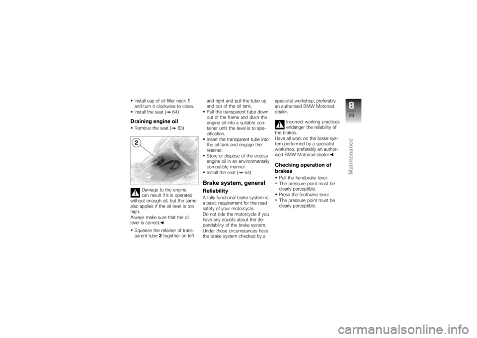
Squeeze the retainer of trans-
parent tube 2together on left and right and pull the tube up
and out of the oil tank.
Pull the transparent tube down
out of the frame and drain the
engine oil into a suitable con-
tainer until the level is to spe-
cification.
Insert the transparent tube into
the oil tank and engage the
retainer.
Store or dispose of the excess
engine oil in an environmentally
compatible manner.
Install the seat ( 64)
Brake system, generalReliabilityA fully functional brake system is
a basic requirement for the road
safety of your motorcycle.
Do not ride the motorcycle if you
have any doubts about the de-
pendability of the brake system.
Under these circumstances have
the brake system checked by a specialist workshop, preferably
an authorised BMW Motorrad
dealer.
Incorrect working practices
endanger the reliability of
the brakes.
Have all work on the brake sys-
tem performed by a specialist
workshop, preferably an author-
ised BMW Motorrad dealer.
Checking operation of
brakesPull the handbrake lever.
The pressure point must be
clearly perceptible.
Press the footbrake lever.
The pressure point must be
clearly perceptible.
899zMaintenance
Page 103 of 166

Checking rear brake pad
thickness
Brake pads worn past
the minimum permissible
brake-pad thickness can cause
a reduction in braking efficiency
and under certain circumstances
they can cause damage to the
brake system.
In order to ensure the dependab-
ility of the brake system, do not
permit the brake pads to wear
past the minimum permissible
brake-pad thickness.
Make sure the ground is level
and firm and place the motor-
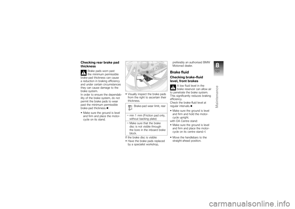
cycle on its stand. Visually inspect the brake pads
from the right to ascertain their
thickness.
Brake-pad wear limit, rear
min 1 mm (Friction pad only,
without backing plate)
Make sure that the brake
disc is not visible through
the bore in the inboard brake
block.
If the brake disc is visible: Have the brake pads replaced
by a specialist workshop, preferably an authorised BMW
Motorrad dealer.
Brake fluidChecking brake-fluid
level, front brakes
A low fluid level in the
brake reservoir can allow air
to penetrate the brake system.
This significantly reduces braking
efficiency.
Check the brake-fluid level at
regular intervals.
Make sure the ground is level
and firm and hold the motor-
cycle upright.
with OA Centre stand:
Make sure the ground is level
and firm and place the motor-
cycle on its centre stand.
Move the handlebars to the
straight-ahead position.
8101zMaintenance
Page 117 of 166
Push the rear wheel stand from
the left into the rear axle.
Install the retaining disc from
the right; to do so, press the
unlock button.
Place your left hand on the
left grab handle of the motor-
cycle4, and your right hand
on the lever of the rear wheel
stand 5. Lift the motorcycle upright,
simultaneously pressing the
lever down until the stand sup-
ports the motorcycle in the up-
right position.
Press the lever down to the
ground.
BulbsGeneral instructionsThe failure of a bulb is signalled
in the display by the defective
lamp symbol. If the brake or rear
light fails, the symbol is accom-
panied by the 'General' warning
light, which lights up yellow. If
the rear light fails the second fil-
ament of the brake light shines
at reduced brightness to double
as a rear light. Even though you
have this substitute rear light, the
8115zMaintenance