2007 Alfa Romeo GT Owner handbook (in English)
-
 1
1 -
 2
2 -
 3
3 -
 4
4 -
 5
5 -
 6
6 -
 7
7 -
 8
8 -
 9
9 -
 10
10 -
 11
11 -
 12
12 -
 13
13 -
 14
14 -
 15
15 -
 16
16 -
 17
17 -
 18
18 -
 19
19 -
 20
20 -
 21
21 -
 22
22 -
 23
23 -
 24
24 -
 25
25 -
 26
26 -
 27
27 -
 28
28 -
 29
29 -
 30
30 -
 31
31 -
 32
32 -
 33
33 -
 34
34 -
 35
35 -
 36
36 -
 37
37 -
 38
38 -
 39
39 -
 40
40 -
 41
41 -
 42
42 -
 43
43 -
 44
44 -
 45
45 -
 46
46 -
 47
47 -
 48
48 -
 49
49 -
 50
50 -
 51
51 -
 52
52 -
 53
53 -
 54
54 -
 55
55 -
 56
56 -
 57
57 -
 58
58 -
 59
59 -
 60
60 -
 61
61 -
 62
62 -
 63
63 -
 64
64 -
 65
65 -
 66
66 -
 67
67 -
 68
68 -
 69
69 -
 70
70 -
 71
71 -
 72
72 -
 73
73 -
 74
74 -
 75
75 -
 76
76 -
 77
77 -
 78
78 -
 79
79 -
 80
80 -
 81
81 -
 82
82 -
 83
83 -
 84
84 -
 85
85 -
 86
86 -
 87
87 -
 88
88 -
 89
89 -
 90
90 -
 91
91 -
 92
92 -
 93
93 -
 94
94 -
 95
95 -
 96
96 -
 97
97 -
 98
98 -
 99
99 -
 100
100 -
 101
101 -
 102
102 -
 103
103 -
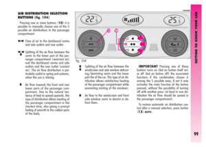
 104
104 -
 105
105 -
 106
106 -
 107
107 -
 108
108 -
 109
109 -
 110
110 -
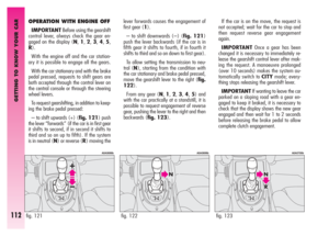
 111
111 -
 112
112 -
 113
113 -
 114
114 -
 115
115 -
 116
116 -
 117
117 -
 118
118 -
 119
119 -
 120
120 -
 121
121 -
 122
122 -
 123
123 -
 124
124 -
 125
125 -
 126
126 -
 127
127 -
 128
128 -
 129
129 -
 130
130 -
 131
131 -
 132
132 -
 133
133 -
 134
134 -
 135
135 -
 136
136 -
 137
137 -
 138
138 -
 139
139 -
 140
140 -
 141
141 -
 142
142 -
 143
143 -
 144
144 -
 145
145 -
 146
146 -
 147
147 -
 148
148 -
 149
149 -
 150
150 -
 151
151 -
 152
152 -
 153
153 -
 154
154 -
 155
155 -
 156
156 -
 157
157 -
 158
158 -
 159
159 -
 160
160 -
 161
161 -
 162
162 -
 163
163 -
 164
164 -
 165
165 -
 166
166 -
 167
167 -
 168
168 -
 169
169 -
 170
170 -
 171
171 -
 172
172 -
 173
173 -
 174
174 -
 175
175 -
 176
176 -
 177
177 -
 178
178 -
 179
179 -
 180
180 -
 181
181 -
 182
182 -
 183
183 -
 184
184 -
 185
185 -
 186
186 -
 187
187 -
 188
188 -
 189
189 -
 190
190 -
 191
191 -
 192
192 -
 193
193 -
 194
194 -
 195
195 -
 196
196 -
 197
197 -
 198
198 -
 199
199 -
 200
200 -
 201
201 -
 202
202 -
 203
203 -
 204
204 -
 205
205 -
 206
206 -
 207
207 -
 208
208 -
 209
209 -
 210
210 -
 211
211 -
 212
212 -
 213
213 -
 214
214 -
 215
215 -
 216
216 -
 217
217 -
 218
218 -
 219
219 -
 220
220 -
 221
221 -
 222
222 -
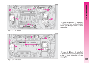
 223
223 -
 224
224 -
 225
225 -
 226
226 -
 227
227 -
 228
228 -
 229
229 -
 230
230 -
 231
231 -
 232
232 -
 233
233 -
 234
234 -
 235
235 -
 236
236 -
 237
237 -
 238
238 -
 239
239 -
 240
240 -
 241
241 -
 242
242 -
 243
243 -
 244
244 -
 245
245 -
 246
246 -
 247
247 -
 248
248 -
 249
249 -
 250
250 -
 251
251 -
 252
252 -
 253
253 -
 254
254 -
 255
255 -
 256
256 -
 257
257 -
 258
258 -
 259
259 -
 260
260 -
 261
261 -
 262
262 -
 263
263 -
 264
264 -
 265
265 -
 266
266 -
 267
267 -
 268
268 -
 269
269 -
 270
270
 IN AN EMERGENCY
207
fig. 53 - Fuse box near the battery
A0A0137b
fig. 54 - Fuse box on battery positive terminal
A0A0215b")
 IN AN EMERGENCY
208
30
30
10
7.5
15
7.5
7.5 F03 (MAXI-FUSE)
F73 (MAXI-FUSE)
F13
F31
F39
F19
F31
SERVICES FIGURE FUSE AMPERES
Hazard warning lights
Right dipped-beam headlight
Left dipped-beam headli")
 IN AN EMERGENCY
209
15
15
7.5
15
15
30
30
20
15
7.5
7.5
20
20
15
7.5
15
7.5 F32
F32
F51
F39
F39
F40
F43
F44
F45
F41
F35
F38
F09
F39
F17
F11
F49
SERVICES FIGURE FUSE AMPERES
Key-operated +30
Selespeed")
 Volumetric sensors
ESP system sensor
Steering angle sensor
EOBD system diagnosis socket
Cell phone provision
Driver’s door control unit supply
Passenger’s door control unit supply
Control l")
 IN AN EMERGENCY
211
40
30
50
15
15
15
15
25
7.5
15
15
30
30
50
20
150
40
60
20 F05 (MAXI-FUSE)
F06 (MAXI-FUSE)
F07 (MAXI-FUSE)
F10
F21
F22
F21
F60 (*)
F16
F61 (*)
F62 (*)
F08
F72 (MAXI-FUSE)
F01 (MAXI")
 IN AN EMERGENCY
212
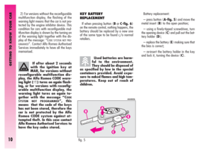
IN THE EVENT OF A FLAT BATTERY
Before anything else, you are advised to
read the precautions for preventing the bat-
tery from draining and for ensuring long life
in the “car mai")
 IN AN EMERGENCY
213
IF THE CAR IS TO BE TOWED
The tow ring supplied with the car is
housed in the tool box under the boot mat.
To install the tow ring, proceed as follows:
– Take the tow ring from")
 IN AN EMERGENCY
214
Take care when position-
ing the arms of the lift or
workshop lift to avoid dam-
aging the side strips.
USING AN ARM LIFT OR
WORKSHOP LIFT
The car must only be lifted laterally po")