Page 17 of 84
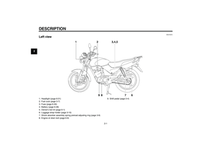
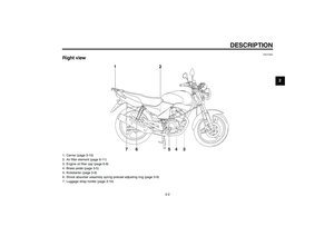
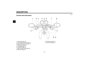
INSTRUMENT AND CONTROL FUNCTIONS
3-3
3
EAU11851
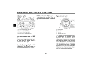
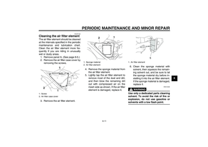
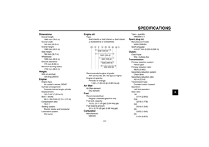
Tachometer The electric tachometer allows the rider
to monitor the engine speed and keep it
within the ideal power range.CAUTION:
ECA10031
Do not operate the engine in the ta-
chometer red zone.Red zone: 10000 r/min and above
EAU37050
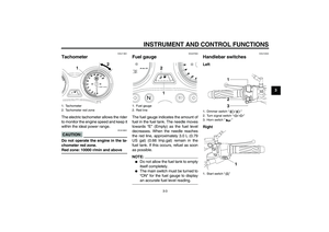
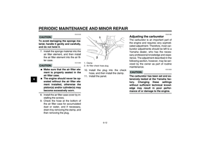
Fuel gauge The fuel gauge indicates the amount of
fuel in the fuel tank. The needle moves
towards “E” (Empty) as the fuel level
decreases. When the needle reaches
the red line, approximately 3.0 L (0.79
US gal) (0.66 Imp.gal) remain in the
fuel tank. If this occurs, refuel as soon
as possible.NOTE:�
Do not allow the fuel tank to empty
itself completely.
�
The main switch must be turned to
“ON” for the fuel gauge to displayan accurate fuel level reading.
EAU12343
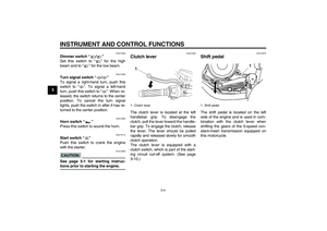
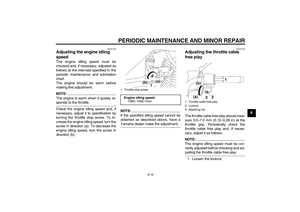
Handlebar switches Left
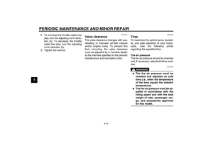
Right
1. Tachometer
2. Tachometer red zone
1. Fuel gauge
2. Red line
1. Dimmer switch “/”
2. Turn signal switch “/”
3. Horn switch “”
1. Start switch “”
U3D9E0E0.book Page 3 Saturday, December 25, 2004 11:35 AM
Page 18 of 84

INSTRUMENT AND CONTROL FUNCTIONS
3-4
3
EAU12400
Dimmer switch “/”
Set this switch to “” for the high
beam and to “” for the low beam.
EAU12460
Turn signal switch “/”
To signal a right-hand turn, push this
switch to “”. To signal a left-hand
turn, push this switch to “”. When re-
leased, the switch returns to the center
position. To cancel the turn signal
lights, push the switch in after it has re-
turned to the center position.
EAU12500
Horn switch “”
Press this switch to sound the horn.
EAU12710
Start switch “”
Push this switch to crank the engine
with the starter.CAUTION:
ECA10050
See page 5-1 for starting instruc-tions prior to starting the engine.
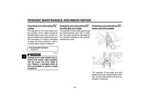
EAU31640
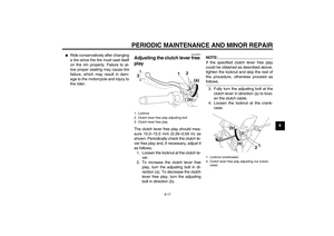
Clutch lever The clutch lever is located at the left
handlebar grip. To disengage the
clutch, pull the lever toward the handle-
bar grip. To engage the clutch, release
the lever. The lever should be pulled
rapidly and released slowly for smooth
clutch operation.
The clutch lever is equipped with a
clutch switch, which is part of the start-
ing circuit cut-off system. (See page
3-10.)
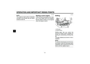
EAU12870
Shift pedal The shift pedal is located on the left
side of the engine and is used in com-
bination with the clutch lever when
shifting the gears of the 5-speed con-
stant-mesh transmission equipped on
this motorcycle.
1. Clutch lever
1. Shift pedal
U3D9E0E0.book Page 4 Saturday, December 25, 2004 11:35 AM
Page 19 of 84
INSTRUMENT AND CONTROL FUNCTIONS
3-5
3
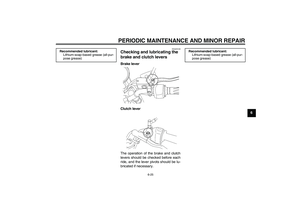
EAU12890
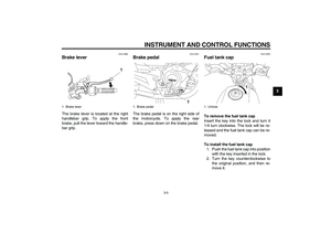
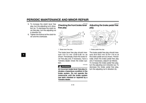
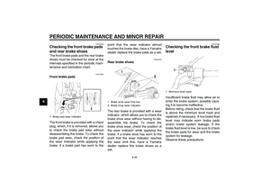
Brake lever The brake lever is located at the right
handlebar grip. To apply the front
brake, pull the lever toward the handle-
bar grip.
EAU12941
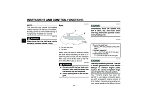
Brake pedal The brake pedal is on the right side of
the motorcycle. To apply the rear
brake, press down on the brake pedal.
EAU13000
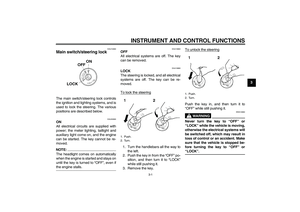
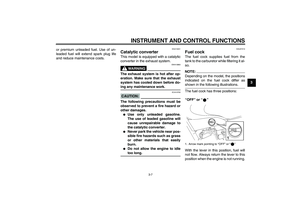
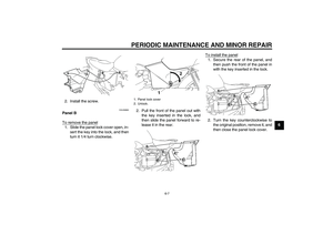
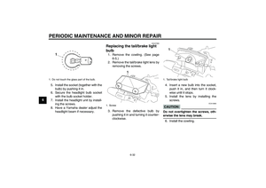
Fuel tank cap To remove the fuel tank cap
Insert the key into the lock and turn it
1/4 turn clockwise. The lock will be re-
leased and the fuel tank cap can be re-
moved.
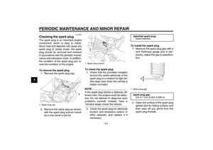
To install the fuel tank cap
1. Push the fuel tank cap into position
with the key inserted in the lock.
2. Turn the key counterclockwise to
the original position, and then re-
move it.
1. Brake lever
1. Brake pedal
1. Unlock.
U3D9E0E0.book Page 5 Saturday, December 25, 2004 11:35 AM
Page 20 of 84

INSTRUMENT AND CONTROL FUNCTIONS
3-6
3
NOTE:The fuel tank cap cannot be installed
unless the key is in the lock. In addition,
the key cannot be removed if the cap isnot properly installed and locked.
WARNING
EWA11140
Make sure that the fuel tank cap isproperly installed before riding.
EAU13220
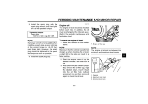
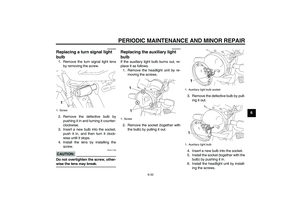
Fuel Make sure that there is sufficient fuel in
the tank. When refueling, be sure to in-
sert the pump nozzle into the fuel tank
filler hole and to fill the tank to the bot-
tom of the filler tube as shown.
WARNING
EWA10880
�
Do not overfill the fuel tank, oth-
erwise it may overflow when the
fuel warms up and expands.
�
Avoid spilling fuel on the hot en-gine.
CAUTION:
ECA10070
Immediately wipe off spilled fuel
with a clean, dry, soft cloth, since
fuel may deteriorate painted surfac-es or plastic parts.
EAU13320
CAUTION:
ECA11400
Use only unleaded gasoline. The use
of leaded gasoline will cause severe
damage to internal engine parts,
such as the valves and piston rings,as well as to the exhaust system.
Your Yamaha engine has been de-
signed to use regular unleaded gaso-
line with a research octane number of
91 or higher. If knocking (or pinging) oc-
curs, use a gasoline of a different brand
1. Fuel tank filler tube
2. Fuel level
Recommended fuel:
REGULAR UNLEADED GASOLINE
ONLY
Fuel tank capacity:
12.0 L (3.17 US gal) (2.64 Imp.gal)
Fuel reserve amount:
3.0 L (0.79 US gal) (0.66 Imp.gal)
U3D9E0E0.book Page 6 Saturday, December 25, 2004 11:35 AM
Page 21 of 84

INSTRUMENT AND CONTROL FUNCTIONS
3-7
3 or premium unleaded fuel. Use of un-
leaded fuel will extend spark plug life
and reduce maintenance costs.
EAU13431
Catalytic converter This model is equipped with a catalytic
converter in the exhaust system.
WARNING
EWA10860
The exhaust system is hot after op-
eration. Make sure that the exhaust
system has cooled down before do-ing any maintenance work.CAUTION:
ECA10700
The following precautions must be
observed to prevent a fire hazard or
other damages.�
Use only unleaded gasoline.
The use of leaded gasoline will
cause unrepairable damage to
the catalytic converter.
�
Never park the vehicle near pos-
sible fire hazards such as grass
or other materials that easily
burn.
�
Do not allow the engine to idletoo long.
EAU37210
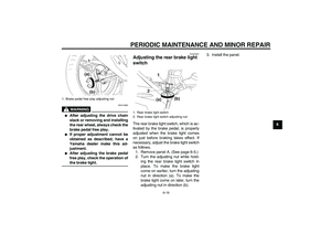
Fuel cock The fuel cock supplies fuel from the
tank to the carburetor while filtering it al-
so.NOTE:Depending on the model, the positions
indicated on the fuel cock differ asshown in the following illustrations.
The fuel cock has three positions:
“OFF” or “”
With the lever in this position, fuel will
not flow. Always return the lever to this
position when the engine is not running.1. Arrow mark pointing to “OFF” or “”
U3D9E0E0.book Page 7 Saturday, December 25, 2004 11:35 AM
Page 22 of 84
INSTRUMENT AND CONTROL FUNCTIONS
3-8
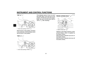
3“ON” or “”
With the lever in this position, fuel flows
to the carburetor. Normal riding is done
with the lever in this position.
“RES” or “”This indicates reserve. If you run out of
fuel while riding, move the lever to this
position. Fill the tank at the first oppor-
tunity. Be sure to set the lever back to
“ON” or “” after refueling!
EAU13590
Starter (choke) lever “” Starting a cold engine requires a richer
air-fuel mixture, which is supplied by
the starter (choke).
Move the lever in direction (a) to turn on
the starter (choke).
Move the lever in direction (b) to turn off
the starter (choke).
1. Arrow mark pointing to “ON” or “”
1. Arrow mark pointing to “RES” or “”
1. Starter (choke) lever “”
U3D9E0E0.book Page 8 Saturday, December 25, 2004 11:35 AM
Page 23 of 84

INSTRUMENT AND CONTROL FUNCTIONS
3-9
3
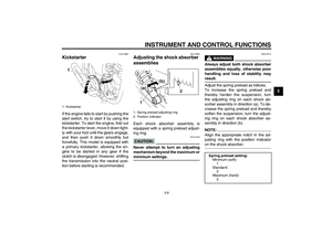
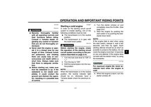
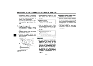
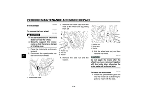
EAU13660
Kickstarter If the engine fails to start by pushing the
start switch, try to start it by using the
kickstarter. To start the engine, fold out
the kickstarter lever, move it down light-
ly with your foot until the gears engage,
and then push it down smoothly but
forcefully. This model is equipped with
a primary kickstarter, allowing the en-
gine to be started in any gear if the
clutch is disengaged. However, shifting
the transmission into the neutral posi-
tion before starting is recommended.
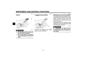
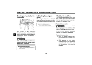
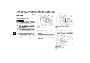
EAU14880
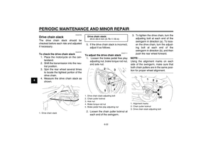
Adjusting the shock absorber
assemblies Each shock absorber assembly is
equipped with a spring preload adjust-
ing ring.CAUTION:
ECA10100
Never attempt to turn an adjusting
mechanism beyond the maximum orminimum settings.
WARNING
EWA10210
Always adjust both shock absorber
assemblies equally, otherwise poor
handling and loss of stability mayresult.
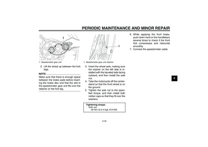
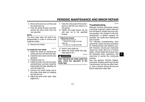
Adjust the spring preload as follows.
To increase the spring preload and
thereby harden the suspension, turn
the adjusting ring on each shock ab-
sorber assembly in direction (a). To de-
crease the spring preload and thereby
soften the suspension, turn the adjust-
ing ring on each shock absorber as-
sembly in direction (b).NOTE:Align the appropriate notch in the ad-
justing ring with the position indicatoron the shock absorber.
1. Kickstarter
1. Spring preload adjusting ring
2. Position indicator
Spring preload setting:
Minimum (soft):
1
Standard:
2
Maximum (hard):
5
U3D9E0E0.book Page 9 Saturday, December 25, 2004 11:35 AM
Page 24 of 84
INSTRUMENT AND CONTROL FUNCTIONS
3-10
3
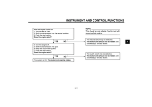
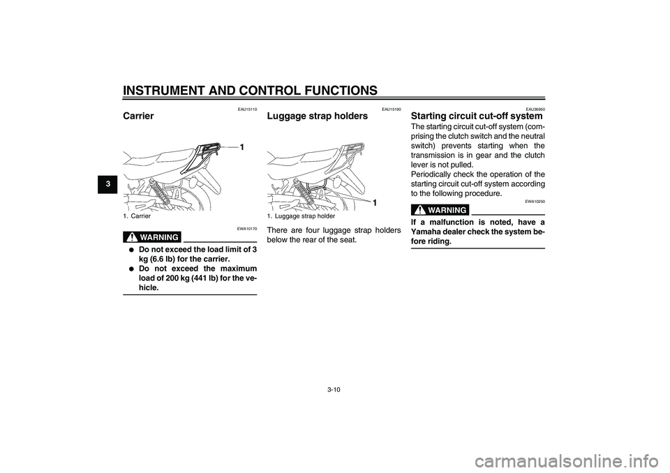
EAU15110
Carrier
WARNING
EWA10170
�
Do not exceed the load limit of 3
kg (6.6 lb) for the carrier.
�
Do not exceed the maximum
load of 200 kg (441 lb) for the ve-hicle.
EAU15190
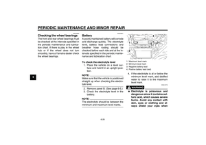
Luggage strap holders There are four luggage strap holders
below the rear of the seat.
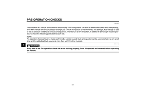
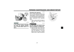
EAU36950
Starting circuit cut-off system The starting circuit cut-off system (com-
prising the clutch switch and the neutral
switch) prevents starting when the
transmission is in gear and the clutch
lever is not pulled.
Periodically check the operation of the
starting circuit cut-off system according
to the following procedure.
WARNING
EWA10250
If a malfunction is noted, have a
Yamaha dealer check the system be-fore riding.
1. Carrier
1. Luggage strap holder
chapter3 Page 10 Friday, January 7, 2005 4:04 PM