Page 73 of 84

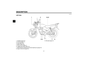
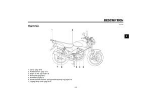
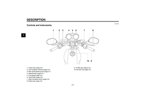
MOTORCYCLE CARE AND STORAGE
7-3
7
�
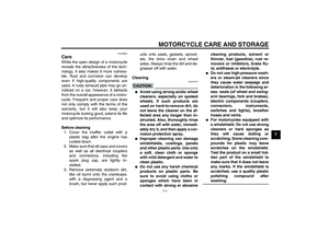
Never apply oil or wax to any
rubber and plastic parts, but
treat them with a suitable care
product.
�
Avoid using abrasive polishing
compounds as they will wearaway the paint.
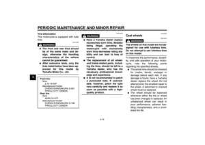
NOTE:Consult a Yamaha dealer for advice onwhat products to use.
EAU37220
Storage Short-term
Always store your motorcycle in a cool,
dry place and, if necessary, protect it
against dust with a porous cover.CAUTION:
ECA10810
�
Storing the motorcycle in a
poorly ventilated room or cover-
ing it with a tarp, while it is still
wet, will allow water and humid-
ity to seep in and cause rust.
�
To prevent corrosion, avoid
damp cellars, stables (because
of the presence of ammonia)
and areas where strong chemi-cals are stored.
Long-term
Before storing your motorcycle for sev-
eral months:
1. Follow all the instructions in the
“Care” section of this chapter.
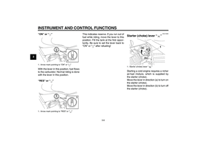
2. Turn the fuel cock lever to “OFF” or
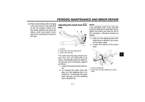
“”.3. Drain the carburetor float chamber
by loosening the drain bolt; this will
prevent fuel deposits from building
up. Pour the drained fuel into the
fuel tank.
4. Fill up the fuel tank and add fuel
stabilizer (if available) to prevent
the fuel tank from rusting and the
fuel from deteriorating.
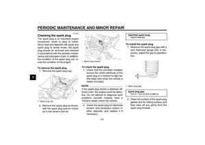
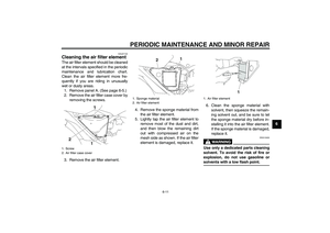
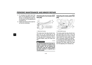
5. Perform the following steps to pro-
tect the cylinder, piston rings, etc.
from corrosion.
a. Remove the spark plug cap
and spark plug.
b. Pour a teaspoonful of engine oil
into the spark plug bore.
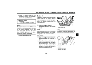
c. Install the spark plug cap onto
the spark plug, and then place
the spark plug on the cylinder
head so that the electrodes are
grounded. (This will limit spark-
ing during the next step.)
d. Turn the engine over several
times with the starter. (This will
coat the cylinder wall with oil.)
e. Remove the spark plug cap
from the spark plug, and then
install the spark plug and the
spark plug cap.
U3D9E0E0.book Page 3 Saturday, December 25, 2004 11:35 AM
Page 74 of 84

MOTORCYCLE CARE AND STORAGE
7-4
7
WARNING
EWA10950
To prevent damage or injury from
sparking, make sure to ground the
spark plug electrodes while turningthe engine over.
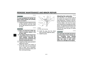
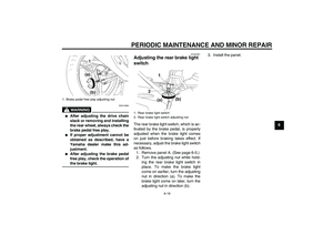
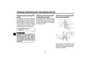
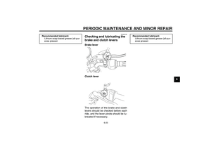
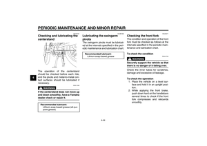
6. Lubricate all control cables and the
pivoting points of all levers and
pedals as well as of the side-
stand/centerstand.
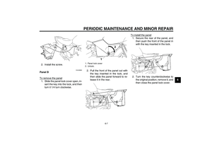
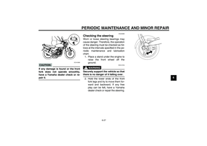
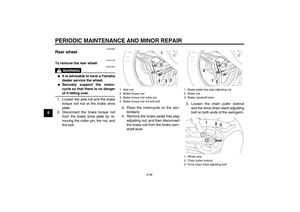
7. Check and, if necessary, correct
the tire air pressure, and then lift
the motorcycle so that both of its
wheels are off the ground. Alterna-
tively, turn the wheels a little every
month in order to prevent the tires
from becoming degraded in one
spot.
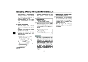
8. Cover the muffler outlet with a
plastic bag to prevent moisture
from entering it.
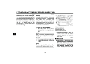
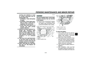
9. Remove the battery and fully
charge it. Store it in a cool, dry
place and charge it once a month.
Do not store the battery in an ex-
cessively cold or warm place [less
than 0 °C (30 °F) or more than 30°C (90 °F)]. For more information
on storing the battery, see page
6-28.
NOTE:Make any necessary repairs beforestoring the motorcycle.
U3D9E0E0.book Page 4 Saturday, December 25, 2004 11:35 AM
Page 75 of 84

Overall width:
745 mm (29.3 in)
Overall height:
1080 mm (42.5 in)
Seat height:
780 mm (30.7 in)
Wheelbase:
1290 mm (50.8 in)
Ground cl")
SPECIFICATIONS
8-1
8
Dimensions:Overall length:
1980 mm (78.0 in)
Overall width:
745 mm (29.3 in)
Overall height:
1080 mm (42.5 in)
Seat height:
780 mm (30.7 in)
Wheelbase:
1290 mm (50.8 in)
Ground clearance:
175 mm (6.89 in)
Minimum turning radius:
1750 mm (68.9 in)Weight:With oil and fuel:
120.0 kg (265 lb)Engine:Engine type:
Air cooled 4-stroke, SOHC
Cylinder arrangement:
Forward-inclined single cylinder
Displacement:
123.7 cm³ (7.55 cu.in)
Bore × stroke:
54.0 × 54.0 mm (2.13 × 2.13 in)
Compression ratio:
10.0 :1
Starting system:
Electric starter and kickstarter
Lubrication system:
Wet sump
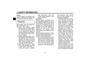
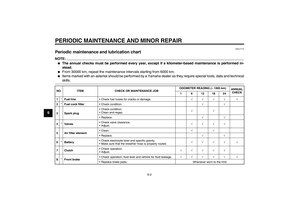
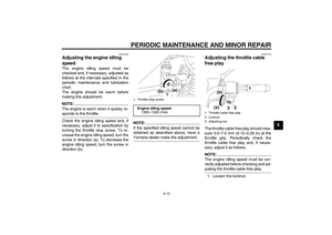
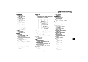
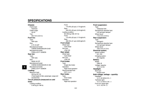
Engine oil:Type:
SAE10W30 or SAE10W40 or SAE15W40
or SAE20W40 or SAE20W50
Recommended engine oil grade:
API service SE, SF, SG type or higher
Engine oil quantity:
Periodic oil change:
1.00 L (1.06 US qt) (0.88 Imp.qt)Air filter:Air filter element:
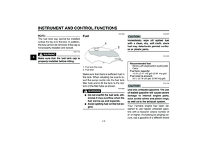
Dry elementFuel:Recommended fuel:
Regular unleaded gasoline only
Fuel tank capacity:
12.0 L (3.17 US gal) (2.64 Imp.gal)
Fuel reserve amount:
3.0 L (0.79 US gal) (0.66 Imp.gal)Carburetor:Manufacturer:
MIKUNIType × quantity:
VM22SH x 1
Spark plug (s):Manufacturer/model:
NGK/CR6HSA
Spark plug gap:
0.6–0.7 mm (0.024–0.028 in)Clutch:Clutch type:
Wet, multiple-discTransmission:Primary reduction system:
Helical gear
Primary reduction ratio:
68/20 (3.400)
Secondary reduction system:
Chain drive
Secondary reduction ratio:
45/14 (3.214)
Transmission type:
Constant mesh 5-speed
Operation:
Left foot operation
Gear ratio:
1st:
37/14 (2.643)
2nd:
32/18 (1.778)
3rd:
25/19 (1.316)
4th:
23/22 (1.045)
5th:
21/24 (0.875)
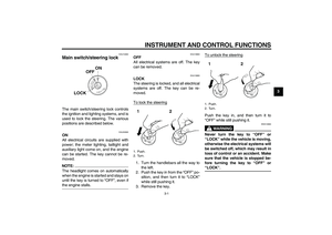
-20 -10 0
10 20 30
40
50 ˚C
SAE 10W-30
SAE 15W-40SAE 20W-40SAE 20W-50
SAE 10W-40
chapter8 Page 1 Friday, January 7, 2005 4:05 PM
Page 76 of 84
Front tire:Type:
With tube
Size:
2.75-18 42P
Manufacturer/model:
CHENG SHIN/SAKURA S-901
Manufacturer/mo")
SPECIFICATIONS
8-2
8
Chassis:Frame type:
Diamond
Caster angle:
26.33 °
Trail:
90.0 mm (3.54 in)Front tire:Type:
With tube
Size:
2.75-18 42P
Manufacturer/model:
CHENG SHIN/SAKURA S-901
Manufacturer/model:
PIRELLI/CITY DEMONRear tire:Type:
With tube
Size:
90/90-18 57P
Manufacturer/model:
CHENG SHIN/SAKURA S-180
Manufacturer/model:
PIRELLI/CITY DEMONLoading:Maximum load:
200 kg (441 lb)
(Total weight of rider, passenger, cargo and
accessories)Tire air pressure (measured on cold
tires):Loading condition:
0–90 kg (0–198 lb)Front:
175 kPa (25 psi) (1.75 kgf/cm²)
Rear:
200 kPa (29 psi) (2.00 kgf/cm²)
Loading condition:
90–200 kg (198–441 lb)
Front:
175 kPa (25 psi) (1.75 kgf/cm²)
Rear:
280 kPa (41 psi) (2.80 kgf/cm²)
Front wheel:Wheel type:
Cast wheel
Rim size:
J18x1.60Rear wheel:Wheel type:
Cast wheel
Rim size:
J18x1.85Front brake:Type:
Single disc brake
Operation:
Right hand operation
Recommended fluid:
DOT 3 or 4Rear brake:Type:
Drum brake
Operation:
Right foot operation
Front suspension:Type:
Telescopic fork
Spring/shock absorber type:
Coil spring/oil damper
Wheel travel:
110.0 mm (4.33 in)Rear suspension:Type:
Swingarm
Spring/shock absorber type:
Coil spring/oil damper
Wheel travel:
105.0 mm (4.13 in)Electrical system:Ignition system:
DC. CDI
Charging system:
AC magnetoBattery:Model:
CB5L-B
Voltage, capacity:
12 V, 5.0 AhHeadlight:Bulb type:
Krypton bulbBulb voltage, wattage × quantity:Headlight:
12 V, 35 W/35.0 W × 1
Tail/brake light:
12 V, 5.0 W/21.0 W × 1
Front turn signal light:
12 V, 10.0 W × 2
chapter8 Page 2 Friday, January 7, 2005 4:05 PM
Page 77 of 84
SPECIFICATIONS
8-3
8
Rear turn signal light:
12 V, 10.0 W × 2
Auxiliary light:
12 V, 5.0 W × 1
Meter lighting:
12 V, 1.7 W × 4
Neutral indicator light:
14 V, 3.0 W × 1
High beam indicator light:
14 V, 3.0 W × 1
Turn signal indicator light:
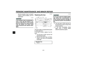
14 V, 3.0 W × 2Fuse:Fuse:
15.0 A
U3D9E0E0.book Page 3 Saturday, December 25, 2004 11:35 AM
Page 78 of 84

CONSUMER INFORMATION
9-1
9
EAU26351
Identification numbers Record the key identification number,
vehicle identification number and mod-
el label information in the spaces pro-
vided below for assistance when
ordering spare parts from a Yamaha
dealer or for reference in case the vehi-
cle is stolen.
KEY IDENTIFICATION NUMBER:
VEHICLE IDENTIFICATION
NUMBER:
MODEL LABEL INFORMATION:
EAU26381
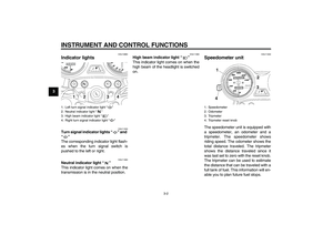
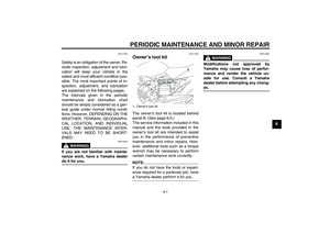
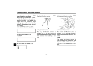
Key identification number
The key identification number is
stamped into the key tag. Record this
number in the space provided and use
it for reference when ordering a new
key.
EAU26400
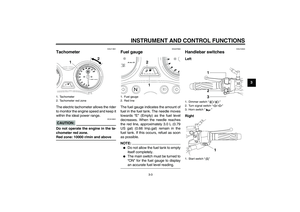
Vehicle identification number
The vehicle identification number is
stamped into the steering head pipe.
Record this number in the space pro-
vided.NOTE:
The vehicle identification number is
used to identify your motorcycle and
may be used to register your motor-
cycle with the licensing authority in yourarea.
1. Key identification number
1. Vehicle identification number
U3D9E0E0.book Page 1 Saturday, December 25, 2004 11:35 AM
Page 79 of 84
CONSUMER INFORMATION
9-2
9
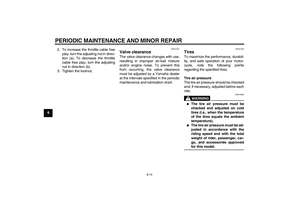
EAU36980
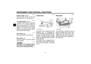
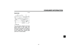
Model label
The model label is affixed to the frame
behind panel B. (See page 6-5.)
Record the information on this label in
the space provided. This information
will be needed when ordering spare
parts from a Yamaha dealer.1. Model label
U3D9E0E0.book Page 2 Saturday, December 25, 2004 11:35 AM
Page 80 of 84

INDEXAAir filter element, cleaning..................... 6-11
Auxiliary light bulb, replacing ................ 6-33BBattery................................................... 6-28
Brake and clutch levers, checking and
lubricating ........................................... 6-25
Brake and shift pedals, checking and
lubricating ........................................... 6-24
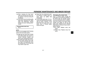
Brake fluid, changing ............................ 6-21
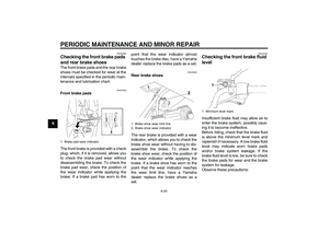
Brake fluid level, checking .................... 6-20
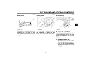
Brake lever .............................................. 3-5
Brake pads and shoes, checking .......... 6-20
Brake pedal ............................................. 3-5
Brake pedal free play, adjusting............ 6-18CCables, checking and lubricating .......... 6-24
Carburetor, adjusting ............................ 6-12
Care ........................................................ 7-1
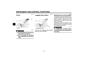
Carrier ................................................... 3-10
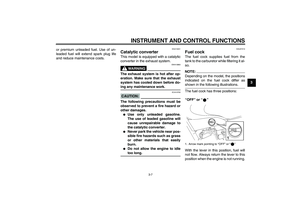
Catalytic converter .................................. 3-7
Centerstand, checking and
lubricating ........................................... 6-26
Clutch lever ............................................. 3-4
Clutch lever free play, adjusting ............ 6-17
Cowling and panels, removing and
installing................................................ 6-5DDimmer switch ........................................ 3-4
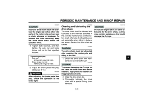
Drive chain, cleaning and lubricating .... 6-23
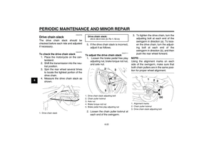
Drive chain slack ................................... 6-22EEngine break-in ....................................... 5-3
Engine idling speed............................... 6-13Engine oil ................................................ 6-9
Engine, starting a warm .......................... 5-2
FFront brake lever free play,
checking ............................................. 6-18
Front fork, checking .............................. 6-26
Fuel......................................................... 3-6
Fuel cock ................................................ 3-7
Fuel consumption, tips for reducing........ 5-3
Fuel gauge.............................................. 3-3
Fuel tank cap .......................................... 3-5
Fuse, replacing ..................................... 6-30HHandlebar switches ................................ 3-3
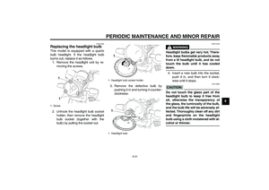
Headlight bulb, replacing ...................... 6-31
High beam indicator light ........................ 3-2
Horn switch ............................................. 3-4IIdentification numbers ............................ 9-1
Indicator lights ........................................ 3-2KKey identification number ....................... 9-1
Kickstarter............................................... 3-9LLuggage strap holders .......................... 3-10MMain switch/steering lock........................ 3-1
Model label ............................................. 9-2NNeutral indicator light .............................. 3-2PParking ................................................... 5-4
Part locations .......................................... 2-1Periodic maintenance and lubrication
chart ...................................................... 6-2
Pre-operation check list........................... 4-2
RRear brake light switch, adjusting ......... 6-19SSafety information ................................... 1-1
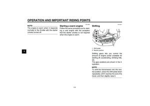
Shifting .................................................... 5-2
Shift pedal ............................................... 3-4
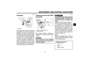
Shock absorber assemblies, adjusting.... 3-9
Spark plug, checking ............................... 6-8
Specifications .......................................... 8-1
Speedometer unit .................................... 3-2
Starter (choke) lever................................ 3-8
Starting a cold engine ............................. 5-1
Starting circuit cut-off system ................ 3-10
Start switch.............................................. 3-4
Steering, checking................................. 6-27
Storage.................................................... 7-3
Swingarm pivots, lubricating ................. 6-26TTachometer ............................................. 3-3
Tail/brake light bulb, replacing .............. 6-32
Throttle cable free play, adjusting ......... 6-13
Throttle grip and cable, checking and
lubricating ........................................... 6-24
Tires ...................................................... 6-14
Tool kit..................................................... 6-1
Troubleshooting .................................... 6-37
Troubleshooting chart ........................... 6-38
Turn signal indicator lights ...................... 3-2
Turn signal light bulb, replacing ............ 6-33
Turn signal switch ................................... 3-4
U3D9E0E0.book Page 1 Saturday, December 25, 2004 11:35 AM


Record the information on this label in
the space provided. This information
wi")