Page 24 of 390

CHAPTER 4ENGINE
FRONT FENDER, SEAT ASSEMBLY
AND FUEL TANK .......................................4-1
MUFFLER ...................................................4-3
CARBURETOR ...........................................4-4
CYLINDER HEAD .....................................4-10
CAMSHAFT AND ROCKER ARMS .........4-15
VALVES AND VALVE SPRINGS .............4-18
CYLINDER AND PISTON .........................4-23
CLUTCH ....................................................4-29
SHIFT SHAFT ...........................................4-37
OIL PUMP .................................................4-39
AC MAGNETO AND
STARTER CLUTCH ..................................4-42
ENGINE REMOVAL ..................................4-47
CRANKCASE AND CRANKSHAFT .........4-51
SHIFT FORK, SHIFT CAM AND
TRANSMISSION .......................................4-54
CHAPTER 5
CHASSIS
FRONT WHEEL AND REAR WHEEL ........5-1
HANDLEBAR ............................................5-10
STEERING AND
FRONT SUSPENSION .............................5-13
SWINGARM ..............................................5-17
CHAPTER 6
ELECTRICAL
ELECTRICAL COMPONENTS AND
WIRING DIAGRAM .....................................6-1
IGNITION SYSTEM .....................................6-2
ELECTRIC STARTING SYSTEM ...............6-6
CHARGING SYSTEM ...............................6-14
CARBURETOR HEATING SYSTEM ........6-16
MAINTENANCE RECORD .......................6-20
Page 44 of 390

1 - 9
GEN
INFO
CONTROL FUNCTIONS
EC155001
THROTTLE GRIP
The throttle grip 1 is located on the right han-
dlebar; it accelerates or decelerates the
engine. For acceleration, turn the grip toward
you; for deceleration, turn it away from you.
1
EC156000
FRONT BRAKE LEVER
The front brake lever 1 is located on the right
handlebar. Pull it toward the handlebar to acti-
vate the front brake.
1
EC157000
REAR BRAKE PEDAL
The rear brake pedal 1 is located on the right
side of the machine. Press down on the brake
pedal to activate the rear brake.
1
FUEL COCK
The fuel cock supplies fuel from the tank to
carburetor while filtering the fuel. The fuel cock
has the three positions:
OFF: With the lever in this position, fuel will not flow. Always return the lever to this posi-
tion when the engine is not running.
ON: With the lever in this position, fuel flows to the carburetor. Normal riding is done
with the lever in this position.
RES: This indicates reserve. If you run out of fuel while riding, move the lever to this
position. FILL THE TANK AT THE FIRST
OPPORTUNITY. BE SURE TO SET
THE LEVER TO “ON ” AFTER REFUEL-
ING.
Page 57 of 390

SPEC
2 - 2
Oil capacity:
Engine oil Periodic oil change 0.8 L (0.70 Imp qt, 0.85 US qt)
Total amount 1.0 L (0.88 Imp qt, 1.06 US qt)
Air filter: Wet element
Fuel: Type Unleaded gasoline only (USA, AUS and NZ) Regular unleaded gasoline only
(CDN, Europe and ZA)
Tank capacity 3.1 L (0.68 Imp gal, 0.82 US gal)
Reserve amount 0.4 L (0.09 Imp gal, 0.11 US gal)
Carburetor: Type VM11
Manufacturer MIKUNI
Spark plug: Type CR7HSA
Manufacturer NGK
Gap 0.6 ~ 0.7 mm (0.024 ~ 0.028 in)
Clutch type: Wet, multiple-disc and centrifugal automatic
Transmission: Primary reduction system Spur gear
Primary reduction ratio 67/18 (3.722)
Secondary reduction system Chain drive
Secondary reduction ratio 37/13 (2.846)
Transmission type Constant mesh, 3-speed
Operation Left foot operation
Gear ratio: 1st 39/12 (3.250) 2nd 33/19 (1.736)
3rd 28/23 (1.217)
Chassis: Frame type Steel tube backbone
Caster angle 25.50 °
Trail 34.0 mm (1.34 in)
Tire: Type With tube
Size (front) 2.50-10 4PR
Size (rear) 2.50-10 4PR
Manufacturer (front and rear) CHENG SHIN
Type (front and rear) KNOBBY
Tire pressure (front and rear) 100 kPa (1.00 kgf/cm
2, 14.2 psi)
Brake: Front brake type Drum brake
Operation Right hand operation
Rear brake type Drum brake
Operation Right foot operation
GENERAL SPECIFICATIONS
1
2
3
4
5
6
Page 64 of 390
SPEC
2 - 9
Carburetor:
I. D. mark 1P61 00 ----
Main jet (M.J) #62.5 ----
Main nozzle (N.J) E-2M ----
Main air jet (M.A.J) ø 1.4 ----
Jet needle (J.N) 4DL22-1 ----
Cutaway (C.A) 2.5 ----
Pilot outlet (P.O) ø 0.8 × 1.5 ----
Pilot jet (P.J) #12.5 ----
Valve seat size (V.S) ø 1.2 ----
Starter jet 1 (G.S.1) #20 ----
Starter jet 2 (G.S.2) ø 0.6 ----
Float height (F.H) 18.5 mm (0.73 in) ----
Fuel level (F.L) 2.0 ~ 3.0 mm (0.08 ~ 0.12 in) ----
Engine idle speed 1,600 ~ 1,800 r/min ----
Lubrication system: Oil filter type Wire mesh type ----
Oil pump type Trochoid type ----
Inner-rotor-to-outer-rotor-tip clearance 0.15 mm or less (0.0061 in or less)0.20 mm
(0.0079 in)
Outer-rotor-to-oil-pump-housing clearance 0.07 mm (0.0028 in)0.15 mm
(0.0059 in)
Oil-pump-housing-to-inner-rotor-and-outer-
rotor clearance 0.06 ~ 0.10 mm
(0.0024 ~ 0.0039 in)0.17 mm
(0.0067 in)
Item Standard Limit
MAINTENANCE SPECIFICATIONS
Page 65 of 390
SPEC
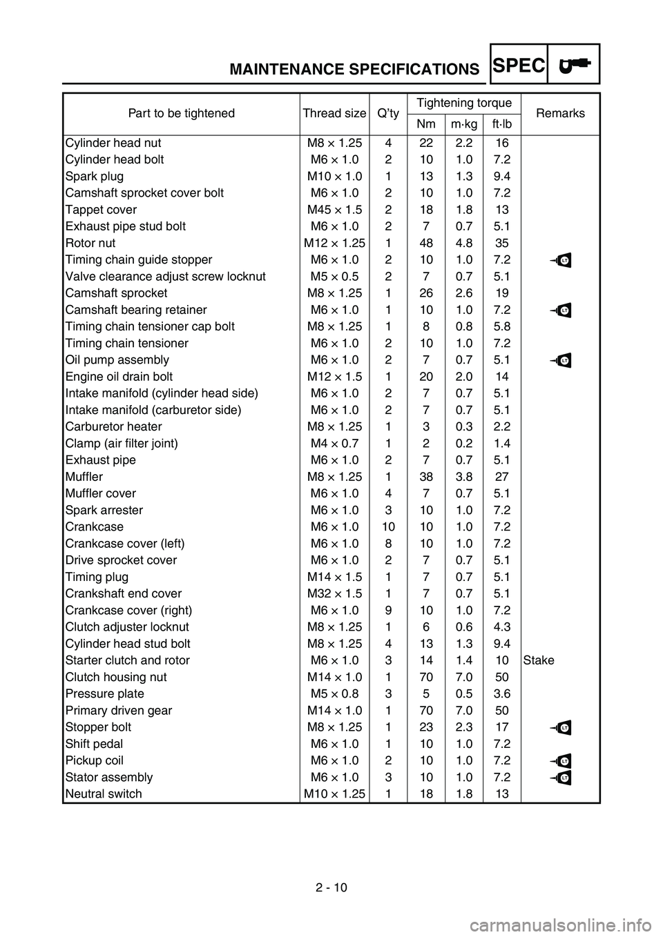
2 - 10
Part to be tightened Thread size Q
’ty Tightening torque
Remarks
Nm m ·kg ft ·lb
Cylinder head nut M8 × 1.25 4 22 2.2 16
Cylinder head bolt M6 × 1.0 2 10 1.0 7.2
Spark plug M10 × 1.0 1 13 1.3 9.4
Camshaft sprocket cover bolt M6 × 1.0 2 10 1.0 7.2
Tappet cover M45 × 1.5 2 18 1.8 13
Exhaust pipe stud bolt M6 × 1.0 2 7 0.7 5.1
Rotor nut M12 × 1.25 1 48 4.8 35
Timing chain guide stopper M6 × 1.0 2 10 1.0 7.2
LT
Valve clearance adjust screw locknut M5 × 0.5 2 7 0.7 5.1
Camshaft sprocket M8 × 1.25 1 26 2.6 19
Camshaft bearing retainer M6 × 1.0 1 10 1.0 7.2
LT
Timing chain tensioner cap bolt M8 × 1.25 1 8 0.8 5.8
Timing chain tensioner M6 × 1.0 2 10 1.0 7.2
Oil pump assembly M6 × 1.0 2 7 0.7 5.1
LT
Engine oil drain bolt M12 × 1.5 1 20 2.0 14
Intake manifold (cylinder head side) M6 × 1.0 2 7 0.7 5.1
Intake manifold (carburetor side) M6 × 1.0 2 7 0.7 5.1
Carburetor heater M8 × 1.25 1 3 0.3 2.2
Clamp (air filter joint) M4 × 0.7 1 2 0.2 1.4
Exhaust pipe M6 × 1.0 2 7 0.7 5.1
Muffler M8 × 1.25 1 38 3.8 27
Muffler cover M6 × 1.0 4 7 0.7 5.1
Spark arrester M6 × 1.0 3 10 1.0 7.2
Crankcase M6 × 1.0 10 10 1.0 7.2
Crankcase cover (left) M6 × 1.0 8 10 1.0 7.2
Drive sprocket cover M6 × 1.0 2 7 0.7 5.1
Timing plug M14 × 1.5 1 7 0.7 5.1
Crankshaft end cover M32 × 1.5 1 7 0.7 5.1
Crankcase cover (right) M6 × 1.0 9 10 1.0 7.2
Clutch adjuster locknut M8 × 1.25 1 6 0.6 4.3
Cylinder head stud bolt M8 × 1.25 4 13 1.3 9.4
Starter clutch and rotor M6 × 1.0 3 14 1.4 10 Stake
Clutch housing nut M14 × 1.0 1 70 7.0 50
Pressure plate M5 × 0.8 3 5 0.5 3.6
Primary driven gear M14 × 1.0 1 70 7.0 50
Stopper bolt M8 × 1.25 1 23 2.3 17
LT
Shift pedal M6 × 1.0 1 10 1.0 7.2
Pickup coil M6 × 1.0 2 10 1.0 7.2
LT
Stator assembly M6 × 1.0 3 10 1.0 7.2LT
Neutral switch M10 × 1.25 1 18 1.8 13
MAINTENANCE SPECIFICATIONS
Page 104 of 390
2 - 17
SPECCABLE ROUTING DIAGRAM
CABLE ROUTING DIAGRAM
1 CDI unit lead
2 Lead guide
3 Carburetor heater
4 Carburetor heater lead flat terminal
5 Carburetor heater lead L-shaped terminal
6 Cable guide
7 Start switch lead
8 Main switch lead
9 Engine stop switch lead 0
Starter cable
A Throttle cable
B Plastic locking tie
C Thermo switch lead
D Spark plug lead
E Carburetor air vent hose
F Crankcase breather hose
G AC magneto leads
H Wire harness
2
É
BÍ
B Ñ
BÏ
F Î
LÕ
\b
8 \b
×
0
\f Ø
E
E Ò 6
\f
7
8
\b
0
\f
C
D
H
H
7
J
I
I
K 8
7
\b
C
0
\f
E H
G 345
Ê
Ì
Ð
ÙÓ
Ô
Ô
È
B
A C
C
B
A
B-B
A-A
C-C
1
Page 106 of 390
2 - 18
SPECCABLE ROUTING DIAGRAM
IAir filter case
J Frame
K Ignition coil
L Brake cable
È Make sure that there is no slack in the wire har-
ness in the area shown in the illustration.
É Pass the wire harness, then the carburetor air
vent hose through the lead guide.
Ê The couplers of identical colors should be con-
nected. Ë
Pass the start switch lead, main switch lead,
engine stop switch lead, throttle cable, and
starter cable through the cable guide.
Ì Route the throttle cable and starter cable under
the start switch lead, main switch lead, and
engine stop switch lead.
2
É
BÍ
B Ñ
BÏ
F Î
LÕ
\b
8 \b
×
0
\f Ø
E
E Ò 6
\f
7
8
\b
0
\f
C
D
H
H
7
J
I
I
K 8
7
\b
C
0
\f
E H
G 345
Ê
Ì
Ð
ÙÓ
Ô
Ô
È
B
A C
C
B
A
B-B
A-A
C-C
1
Page 110 of 390
2 - 20
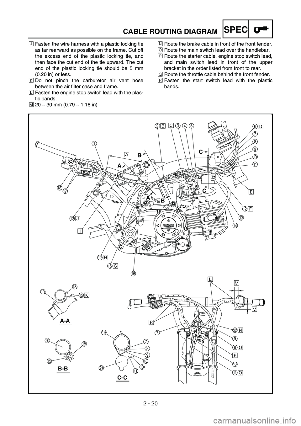
SPECCABLE ROUTING DIAGRAM
ÑFasten the wire harness with a plastic locking tie
as far rearward as possible on the frame. Cut off
the excess end of the plastic locking tie, and
then face the cut end of the tie upward. The cut
end of the plastic locking tie should be 5 mm
(0.20 in) or less.
Ò Do not pinch the carburetor air vent hose
between the air filter case and frame.
Ó Fasten the engine stop switch lead with the plas-
tic bands.
Ô 20 ~ 30 mm (0.79 ~ 1.18 in) Õ
Route the brake cable in front of the front fender.
Ö Route the main switch lead over the handlebar.
× Route the starter cable, engine stop switch lead,
and main switch lead in front of the upper
bracket in the order listed from front to rear.
Ø Route the throttle cable behind the front fender.
Ù Fasten the start switch lead with the plastic
bands.
2
É
BÍ
B Ñ
BÏ
F Î
LÕ
\b
8 \b
×
0
\f Ø
E
E Ò 6
\f
7
8
\b
0
\f
C
D
H
H
7
J
I
I
K 8
7
\b
C
0
\f
E H
G 345
Ê
Ì
Ð
ÙÓ
Ô
Ô
È
B
A C
C
B
A
B-B
A-A
C-C
1