2006 TOYOTA RAV4 balanc
[x] Cancel search: balancPage 1 of 2000

ENGINE - 2AZ-FE ENGINE EG-4
FEATURES OF 2AZ-FE ENGINE
The 2AZ-FE engine has achieved the following performance through the use of the items listed below.
(1) High performance and reliability
(2) Low noise and vibration
(3) Lightweight and compact design
(4) Good serviceability
(5) Clean emission and fuel economy
Section
Item(1)(2)(3)(4)(5)
Engine
A cylinder block made of aluminum alloy along with a
magnesium alloy die-cast cylinder head cover is used.
Engine
ProperA taper squish shape is used for the combustion chamber.p
A resin gear balance shaft is used.
Vl
A timing chain and chain tensioner are used.
Va l v e
MechanismThe shim-less type valve lifters are used.MechanismThe VVT-i system is used.
A chacoal filter is used in the air cleaner cap.
Intake andIntake manifold made of plastic is used.Intake and
ExhaustThe linkless-type throttle body is used.
SystemA thin-wall ceramic TWC (Three-Way Catalytic converter)
is used.
The fuel returnless system is used.
Fuel
System
Quick connectors are used to connect the fuel hose with the
fuel pipe.
System12-hole type fuel injectors with high atomizing performance
are used.
Ignition
SystemIridium-tipped spark plugs are used.
Charging
SystemThe segment conductor type generator is used.
Starting
SystemPS (Planetary reduction-Segment conductor motor) type
starter is used.
The ETCS-i is used.
Engine
Control
The DIS (Direct Ignition System) makes ignition timing
adjustment unnecessary.
Control
SystemThe non-contact type sensor is used in the throttle position
sensor.
The planar type air-fuel ratio sensor is used.
Page 7 of 2000

ENGINE - 2AZ-FE ENGINE
01NEG31Y
No.1 JournalBalance Shaft Drive Gear
Oil Hole
Crank Pin
Balance Weight
01NEG32Y
: Resin Gear
Balance Shaft
HousingBalance Shaft No.1 Balance Shaft No.2Crankshaft
Balance Shaft Drive Gear EG-10
7. Crankshaft
The forged crankshaft has 5 journals and 8 balance weights.
The crankshaft is made of forged steel.
Pin and journal fillets are roll-finished to maintain adequate strength.
The balance shaft drive gear is provided for the crankshaft.
8. Balance Shaft
General
A balance shaft is used to reduce vibrations.
The crankshaft directly drives the No. 1 balance shaft.
In addition, a resin gear is used on the driven side to suppress noise and offer lightweight design.
Page 8 of 2000

ENGINE - 2AZ-FE ENGINE
286EG71
Top Dead Center
Point of Max. Speed
Bottom Dead Center
Point of
Max. SpeedPoint of
Max. Speed 90
286EG72
Inertial Force of Cylinders
No.2 and No.3
Combined Inertial Force of
All Cylinders
Unbalanced Secondary
Inertial Force
Inertial Force of Cylinder
No.1 and No.4Force
Inertial force that cannot be canceled
Crankshaft Angle -90
90270
1800- 180
Inertial Force Generated by the In-line 4 Cylinders
286EG73
090180270
A
BC
DEInertial Force of Balancer
Crankshaft Angle
Secondary Inertial Force
Mass Direction of
Balance Shaft
Inertial Force of
Balancer
Mass Direction of Balance Shaft at Crankshaft AngleEG-11
Operation
In the in-line 4-cylinder engine, the crankshaft
angle for cylinders No.1 and No.4 are exactly at
the opposite (180
) position of cylinders No.2
and No.3. Therefore, the inertial force of the
pistons and the connecting rods of the former 2
cylinders and of the latter 2 cylinders almost
cancel each other. However, because the position
at which the piston reaches its maximum speed
is located toward the top dead center from the
center of the stroke, the upward inertial force is
greater than the downward inertial force. This
unbalanced secondary inertial force is generated
twice for each rotation of the crankshaft.
To cancel the unbalanced secondary inertial force, 2 balance shafts are rotated twice for each rotation of
the crankshaft and generate inertial force in the opposite direction. Also, in order to cancel the inertial force
generated by the balance shaft itself, the balance shaft actually consists of 2 shafts rotating in opposite
directions.
Page 73 of 2000

ENGINE - 2GR-FE ENGINE
285EG14
Knock Pin
Plastic Region
Tightening Bolts
285EG15
Balance Weight
Engine
Front
No. 1 Journal
No. 2 Journal
No. 3 JournalNo. 4 JournalEG-77
6. Connecting Rod and Connecting Rod Bearing
Connecting rods that have been forged for high strength are used for weight reduction.
Knock pins are used at the mating surfaces of the bearing caps of the connecting rod to minimize the
shifting of the bearing caps during assembly.
The connecting rods and caps are made of high-strength steel for weight reduction.
Nutless-type plastic region tightening bolts are used on the connecting rods for a lighter design.
An aluminum bearing is used for the connecting rod bearings.
The connecting rod bearings are reduced in width to reduce friction.
7. Crankshaft
A crankshaft made of forged steel, which excels in rigidity and wear resistance, is used.
The crankshaft has 4 journals and 5 balance weights.
All pin and journal fillets are IH-finished to maintain adequate strength.
Page 167 of 2000
IN–22INTRODUCTION – REPAIR INSTRUCTION
IN
VEHICLE LIFT AND SUPPORT
LOCATIONS
1. NOTICE ABOUT VEHICLE CONDITION WHEN
JACKING UP VEHICLE
(a) The vehicle must be unloaded before jacking up /
lifting up the vehicle. Never jack up / lift up a heavily
loaded vehicle.
(b) When removing heavy parts such as the engine and
transmission, the center of gravity of the vehicle
may shift. To stabilize the vehicle, place a balance
weight in a location where it will not roll or shift, or
use a mission jack to hold the jacking support.
2. NOTICE FOR USING 4 POST LIFT
(a) Follow the safety procedures outlined in the lift
instruction manual.
(b) Use precautionary measures to prevent the free
wheel beam from damaging tires or wheels.
(c) Use wheel chocks to secure the vehicle.
3. NOTICE FOR USING JACK AND SAFETY STAND
(a) Work on a level surface. Use wheel chocks at all
times.
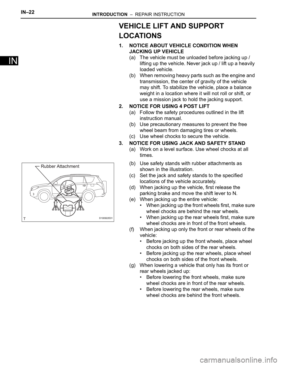
(b) Use safety stands with rubber attachments as
shown in the illustration.
(c) Set the jack and safety stands to the specified
locations of the vehicle accurately.
(d) When jacking up the vehicle, first release the
parking brake and move the shift lever to N.
(e) When jacking up the entire vehicle:
• When jacking up the front wheels first, make sure
wheel chocks are behind the rear wheels.
• When jacking up the rear wheels first, make sure
wheel chocks are in front of the front wheels.
(f) When jacking up only the front or rear wheels of the
vehicle:
• Before jacking up the front wheels, place wheel
chocks on both sides of the rear wheels.
• Before jacking up the rear wheels, place wheel
chocks on both sides of the front wheels.
(g) When lowering a vehicle that only has its front or
rear wheels jacked up:
• Before lowering the front wheels, make sure
wheel chocks are in front of the rear wheels.
• Before lowering the rear wheels, make sure
wheel chocks are behind the front wheels.
D100922E01
Page 377 of 2000
U241E AUTOMATIC TRANSAXLE – UNDERDRIVE CLUTCHAX–249
AX
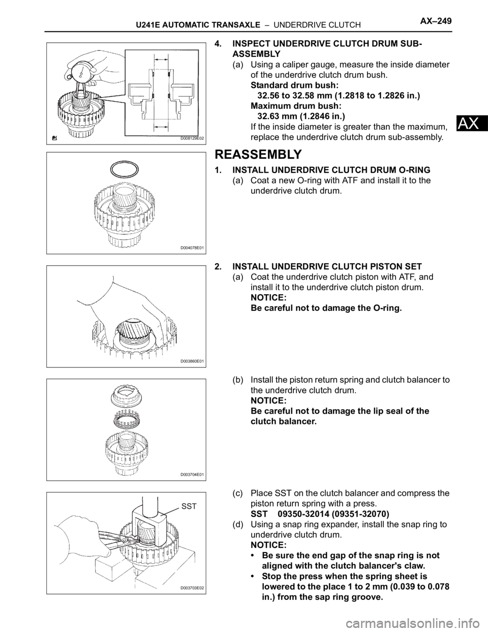
4. INSPECT UNDERDRIVE CLUTCH DRUM SUB-
ASSEMBLY
(a) Using a caliper gauge, measure the inside diameter
of the underdrive clutch drum bush.
Standard drum bush:
32.56 to 32.58 mm (1.2818 to 1.2826 in.)
Maximum drum bush:
32.63 mm (1.2846 in.)
If the inside diameter is greater than the maximum,
replace the underdrive clutch drum sub-assembly.
REASSEMBLY
1. INSTALL UNDERDRIVE CLUTCH DRUM O-RING
(a) Coat a new O-ring with ATF and install it to the
underdrive clutch drum.
2. INSTALL UNDERDRIVE CLUTCH PISTON SET
(a) Coat the underdrive clutch piston with ATF, and
install it to the underdrive clutch piston drum.
NOTICE:
Be careful not to damage the O-ring.
(b) Install the piston return spring and clutch balancer to
the underdrive clutch drum.
NOTICE:
Be careful not to damage the lip seal of the
clutch balancer.
(c) Place SST on the clutch balancer and compress the
piston return spring with a press.
SST 09350-32014 (09351-32070)
(d) Using a snap ring expander, install the snap ring to
underdrive clutch drum.
NOTICE:
• Be sure the end gap of the snap ring is not
aligned with the clutch balancer's claw.
• Stop the press when the spring sheet is
lowered to the place 1 to 2 mm (0.039 to 0.078
in.) from the sap ring groove.
D008129E02
D004078E01
D003860E01
D003704E01
D003703E02
Page 381 of 2000
SS–14SERVICE SPECIFICATIONS – 2AZ-FE ENGINE MECHANICAL
SS
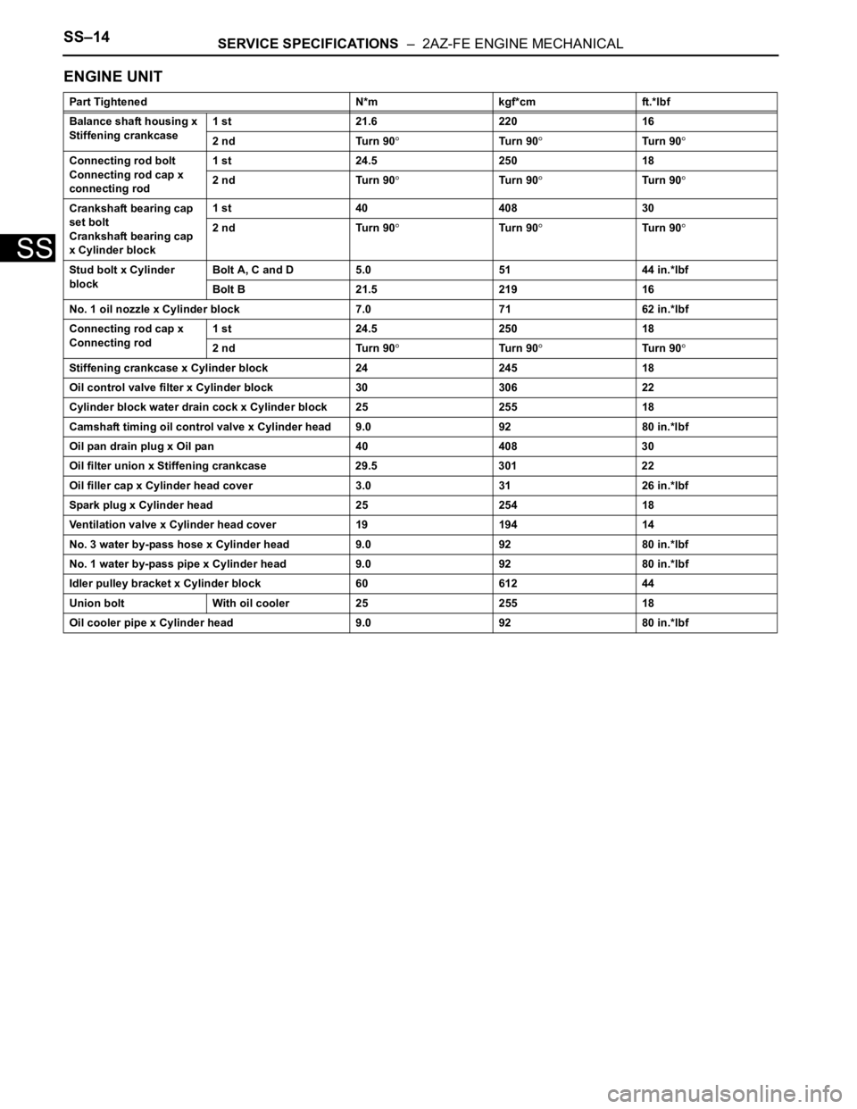
ENGINE UNIT
Part Tightened N*m kgf*cm ft.*lbf
Balance shaft housing x
Stiffening crankcase1 st 21.6 220 16
2 nd Turn 90
Tu r n 9 0Tu r n 9 0
Connecting rod bolt
Connecting rod cap x
connecting rod1 st 24.5 250 18
2 nd Turn 90
Tu r n 9 0Tu r n 9 0
Crankshaft bearing cap
set bolt
Crankshaft bearing cap
x Cylinder block1 st 40 408 30
2 nd Turn 90
Tu r n 9 0Tu r n 9 0
Stud bolt x Cylinder
blockBolt A, C and D 5.0 51 44 in.*lbf
Bolt B 21.5 219 16
No. 1 oil nozzle x Cylinder block 7.0 71 62 in.*lbf
Connecting rod cap x
Connecting rod1 st 24.5 250 18
2 nd Turn 90
Tu r n 9 0Tu r n 9 0
Stiffening crankcase x Cylinder block 24 245 18
Oil control valve filter x Cylinder block 30 306 22
Cylinder block water drain cock x Cylinder block 25 255 18
Camshaft timing oil control valve x Cylinder head 9.0 92 80 in.*lbf
Oil pan drain plug x Oil pan 40 408 30
Oil filter union x Stiffening crankcase 29.5 301 22
Oil filler cap x Cylinder head cover 3.0 31 26 in.*lbf
Spark plug x Cylinder head 25 254 18
Ventilation valve x Cylinder head cover 19 194 14
No. 3 water by-pass hose x Cylinder head 9.0 92 80 in.*lbf
No. 1 water by-pass pipe x Cylinder head 9.0 92 80 in.*lbf
Idler pulley bracket x Cylinder block 60 612 44
Union bolt With oil cooler 25 255 18
Oil cooler pipe x Cylinder head 9.0 92 80 in.*lbf
Page 653 of 2000
EM–1262AZ-FE ENGINE MECHANICAL – ENGINE UNIT
EM
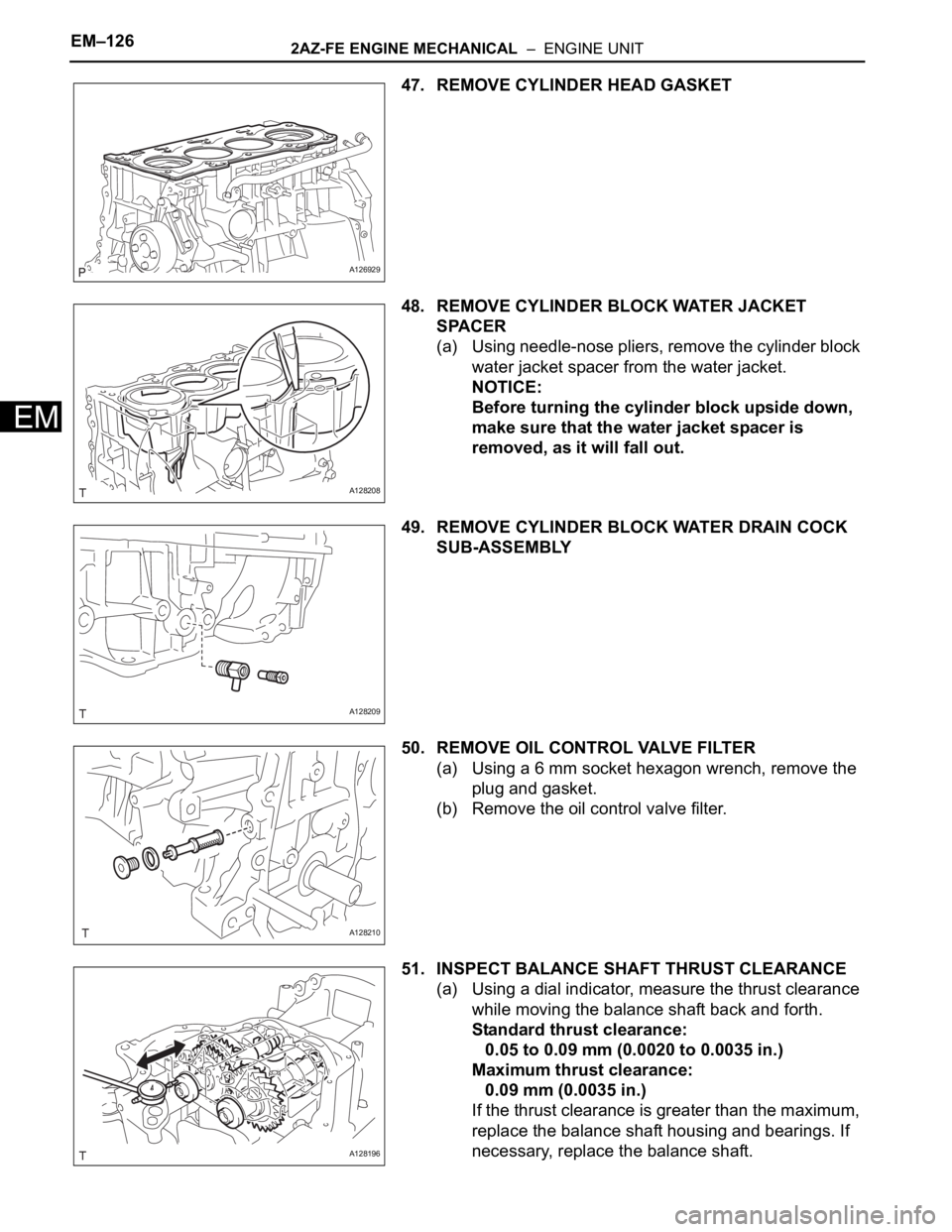
47. REMOVE CYLINDER HEAD GASKET
48. REMOVE CYLINDER BLOCK WATER JACKET
SPACER
(a) Using needle-nose pliers, remove the cylinder block
water jacket spacer from the water jacket.
NOTICE:
Before turning the cylinder block upside down,
make sure that the water jacket spacer is
removed, as it will fall out.
49. REMOVE CYLINDER BLOCK WATER DRAIN COCK
SUB-ASSEMBLY
50. REMOVE OIL CONTROL VALVE FILTER
(a) Using a 6 mm socket hexagon wrench, remove the
plug and gasket.
(b) Remove the oil control valve filter.
51. INSPECT BALANCE SHAFT THRUST CLEARANCE
(a) Using a dial indicator, measure the thrust clearance
while moving the balance shaft back and forth.
Standard thrust clearance:
0.05 to 0.09 mm (0.0020 to 0.0035 in.)
Maximum thrust clearance:
0.09 mm (0.0035 in.)
If the thrust clearance is greater than the maximum,
replace the balance shaft housing and bearings. If
necessary, replace the balance shaft.
A126929
A128208
A128209
A128210
A128196