2006 TOYOTA RAV4 Rear spring
[x] Cancel search: Rear springPage 390 of 2000

SS–64SERVICE SPECIFICATIONS – U241E AUTOMATIC TRANSAXLE
SS
TORQUE SPECIFICATIONS
Automatic Transaxle Assembly
Automatic Transaxle Unit
Part Tightened N*m kgf*cm ft.*lbf
Park/neutral position switch Nut 6.9 70 61 in.*lbf
Bolt 5.4 55 48 in.*lbf
Control shaft lever x Control shaft 12.7 130 9
Shift control cable x Control shaft lever 15 153 11
Transaxle housing x Engine block A bolt 64 653 47
B bolt 46 470 34
Lower side bolt 37 377 27
Torque converter clutch x Drive plate 41 418 30
Engine mounting bracket FR x Transaxle 64 653 47
Oil filler tube x Transaxle 5.5 56 49 in.*lbf
Control cable bracket No.1 x Transaxle 12 122 9
Oil cooler tube clamp x Control cable bracket 5.4 55 48 in.*lbf
Oil cooler inlet tube x Transaxle 34 347 25
Oil cooler outlet tube x Transaxle 34 347 25
Starter x Transaxle37 377 27
Wire harness x Transaxle 13 133 10
Speed sensor (NC) x Transaxle 11 115 8
Speed sensor (NT) x Transaxle 11 112 8
Air cleaner x No. 1 air cleaner inlet 5.0 51 44 in.*lbf
Drain plug x Oil pan47 479 35
Transmission wire x Transaxle 5.4 55 48 in.*lbf
ATF temperature sensor x Valve body 6.6 67 58 in.*lbf
Oil pan x Transaxle7.6 77 67 in.*lbf
Solenoid valve x Valve body Bolt A 6.6 67 58 in.*lbf
B o l t B 11 11 0 8
Valve body x Transaxle 10.8 110 8
Oil strainer x Valve body 11 110 8
Floor shift assembly x Body 12 120 9
Control cable x Body5.0 51 44 in.*lbf
Engine mount bracket RR x Transfer stiffener, plate RH 45 459 34
Part Tightened N*m kgf*cm ft.*lbf
Differential gear lube apply tube x Transaxle housing 9.8 100 7
Front planetary gear lock nut 268 2,732 198
Brake apply tube clamp x Transaxle case 5.4 55 48 in.*lbf
Transaxle case No. 1 plug x Transaxle rear cover 7.4 75 65 in.*lbf
Transaxle rear cover plate x transaxle rear cover sub-assembly 7.5 76 66 in.*lbf
Transaxle rear cover x Transaxle case Bolt A 18.6 190 14
Other bolt 24.5 250 18
Pawl shaft clamp x Transaxle case 9.8 100 7
Oil pump assembly x Transaxle case 22 226 16
Transaxle housing x Transaxle case Bolt A 22.1 225 16.3
Bolt B, C 29.4 300 21.7
Transaxle case No. 1 plug x Transaxle housing 7.4 75 65 in.*lbf
Parking lock pawl bracket x Transaxle case 20 205 15
Detent spring x Transaxle case Bolt A 20 205 15
Bolt B 12 120 9
Page 415 of 2000
BRAKE – BRAKE SYSTEMBR–3
BR
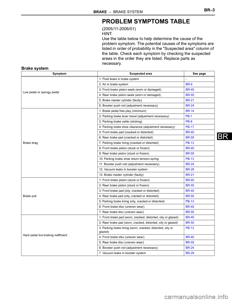
PROBLEM SYMPTOMS TABLE
(2005/11-2006/01)
HINT:
Use the table below to help determine the cause of the
problem symptom. The potential causes of the symptoms are
listed in order of probability in the "Suspected area" column of
the table. Check each symptom by checking the suspected
areas in the order they are listed. Replace parts as
necessary.
Brake system
Symptom Suspected area See page
Low pedal or spongy pedal1. Fluid leaks in brake system -
2. Air in brake systemBR-6
3. Front brake piston seals (worn or damaged)BR-40
4. Rear brake piston seals (worn or damaged)BR-55
5. Brake master cylinder (faulty)BR-21
6. Booster push rod (adjustment necessary)BR-24
Brake drag1. Brake pedal free play (minimum)BR-14
2. Parking brake lever travel (adjustment necessary)PB-1
3. Parking brake cable (sticking)PB-8
4. Parking brake shoe clearance (adjustment necessary)PB-17
5. Front brake pad (cracked or distorted)BR-40
6. Rear brake pad (cracked or distorted)BR-55
7. Parking brake lining (cracked or distorted)PB-13
8. Front brake piston (stuck or frozen)BR-40
9. Rear brake piston (stuck or frozen)BR-55
10. Parking brake shoe return tension springPB-13
11. Booster push rod (adjustment necessary)BR-24
12. Vacuum leaks in booster systemBR-29
13. Brake master cylinder (faulty)BR-21
Brake pull1. Front brake piston (stuck or frozen)BR-40
2. Rear brake piston (stuck or frozen)BR-55
3. Front brake pad (oily, cracked or distorted)BR-40
4. Rear brake pad (oily, cracked or distorted)BR-55
5. Parking brake lining (oily, cracked or distorted)PB-13
6. Front brake disc (uneven wear)BR-40
7. Rear brake disc (uneven wear)BR-55
Hard pedal but braking inefficient1. Front brake pad (worn, cracked, distorted, oily or glazed)BR-40
2. Rear brake pad (worn, cracked, distorted, oily or glazed)BR-55
3. Parking brake lining (worn, cracked, distorted, oily or
glazed)PB-13
4. Front brake disc (uneven wear)BR-40
5. Rear brake disc (uneven wear)BR-55
6. Booster push rod (adjustment necessary)BR-24
7. Vacuum leaks in booster systemBR-29
Page 416 of 2000
BR–4BRAKE – BRAKE SYSTEM
BR
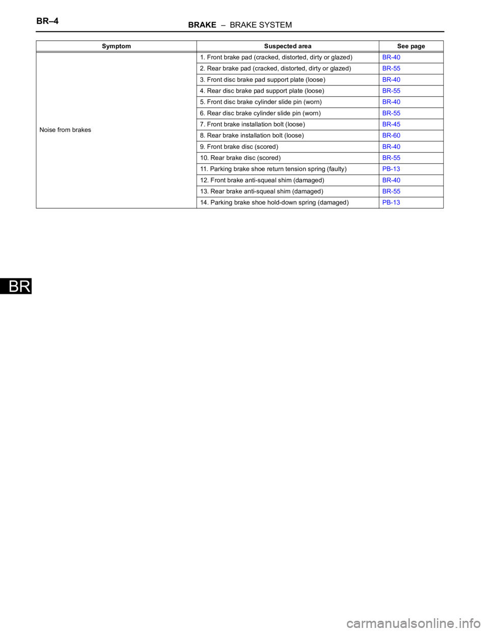
Noise from brakes1. Front brake pad (cracked, distorted, dirty or glazed)BR-40
2. Rear brake pad (cracked, distorted, dirty or glazed)BR-55
3. Front disc brake pad support plate (loose)BR-40
4. Rear disc brake pad support plate (loose)BR-55
5. Front disc brake cylinder slide pin (worn)BR-40
6. Rear disc brake cylinder slide pin (worn)BR-55
7. Front brake installation bolt (loose)BR-45
8. Rear brake installation bolt (loose)BR-60
9. Front brake disc (scored)BR-40
10. Rear brake disc (scored)BR-55
11. Parking brake shoe return tension spring (faulty)PB-13
12. Front brake anti-squeal shim (damaged)BR-40
13. Rear brake anti-squeal shim (damaged)BR-55
14. Parking brake shoe hold-down spring (damaged)PB-13 Symptom Suspected area See page
Page 419 of 2000
MA–12MAINTENANCE – CHASSIS
MA
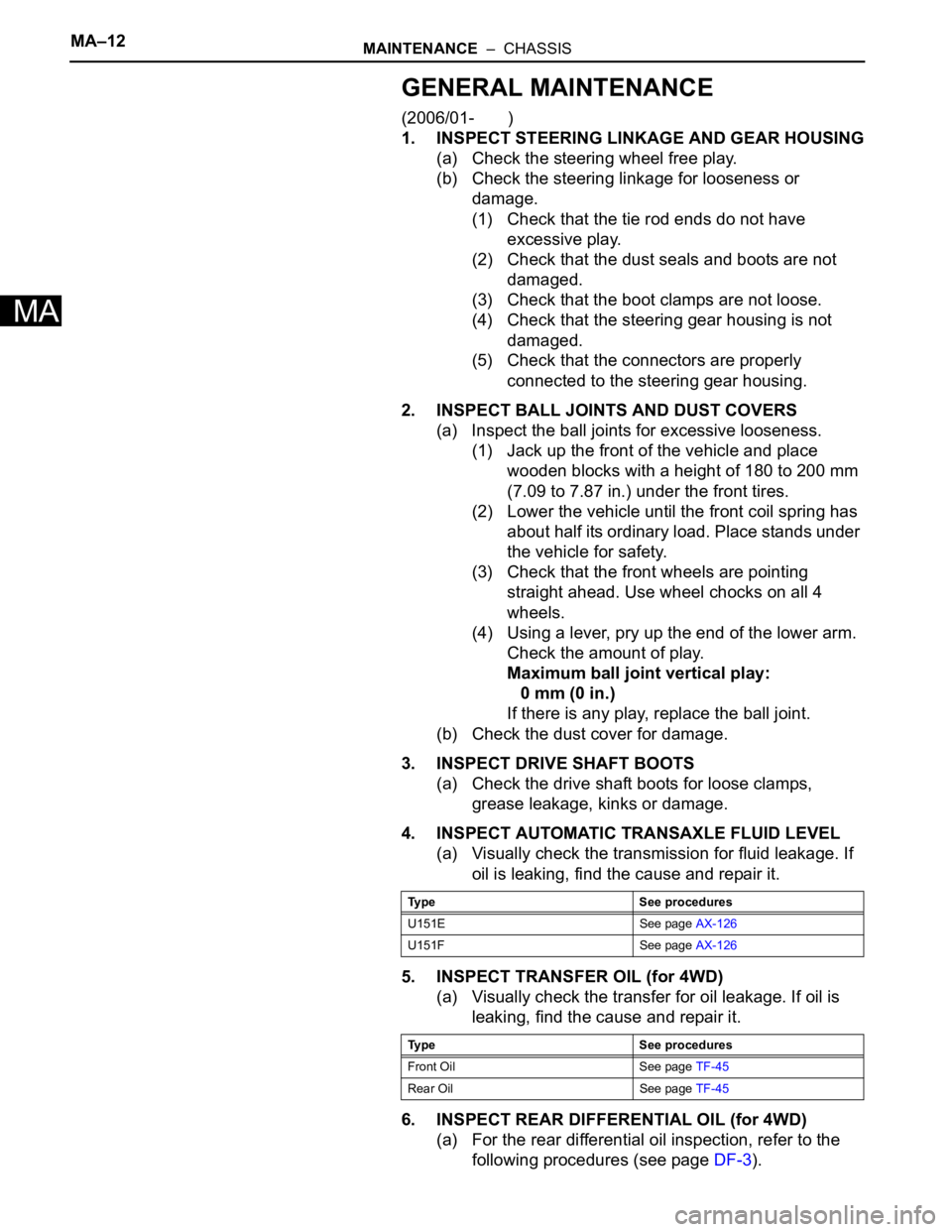
GENERAL MAINTENANCE
(2006/01- )
1. INSPECT STEERING LINKAGE AND GEAR HOUSING
(a) Check the steering wheel free play.
(b) Check the steering linkage for looseness or
damage.
(1) Check that the tie rod ends do not have
excessive play.
(2) Check that the dust seals and boots are not
damaged.
(3) Check that the boot clamps are not loose.
(4) Check that the steering gear housing is not
damaged.
(5) Check that the connectors are properly
connected to the steering gear housing.
2. INSPECT BALL JOINTS AND DUST COVERS
(a) Inspect the ball joints for excessive looseness.
(1) Jack up the front of the vehicle and place
wooden blocks with a height of 180 to 200 mm
(7.09 to 7.87 in.) under the front tires.
(2) Lower the vehicle until the front coil spring has
about half its ordinary load. Place stands under
the vehicle for safety.
(3) Check that the front wheels are pointing
straight ahead. Use wheel chocks on all 4
wheels.
(4) Using a lever, pry up the end of the lower arm.
Check the amount of play.
Maximum ball joint vertical play:
0 mm (0 in.)
If there is any play, replace the ball joint.
(b) Check the dust cover for damage.
3. INSPECT DRIVE SHAFT BOOTS
(a) Check the drive shaft boots for loose clamps,
grease leakage, kinks or damage.
4. INSPECT AUTOMATIC TRANSAXLE FLUID LEVEL
(a) Visually check the transmission for fluid leakage. If
oil is leaking, find the cause and repair it.
5. INSPECT TRANSFER OIL (for 4WD)
(a) Visually check the transfer for oil leakage. If oil is
leaking, find the cause and repair it.
6. INSPECT REAR DIFFERENTIAL OIL (for 4WD)
(a) For the rear differential oil inspection, refer to the
following procedures (see page DF-3).
Type See procedures
U151E See page AX-126
U151F See page AX-126
Type See procedures
Front Oil See page TF-45
Rear Oil See page TF-45
Page 1013 of 2000
AX–234U140F AUTOMATIC TRANSAXLE – DIRECT CLUTCH
AX
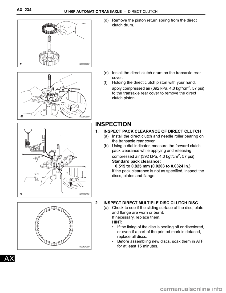
(d) Remove the piston return spring from the direct
clutch drum.
(e) Install the direct clutch drum on the transaxle rear
cover.
(f) Holding the direct clutch piston with your hand,
apply compressed air (392 kPa, 4.0 kgf*cm
2, 57 psi)
to the transaxle rear cover to remove the direct
clutch piston.
INSPECTION
1. INSPECT PACK CLEARANCE OF DIRECT CLUTCH
(a) Install the direct clutch and needle roller bearing on
the transaxle rear cover.
(b) Using a dial indicator, measure the forward clutch
pack clearance while applying and releasing
compressed air (392 kPa, 4.0 kgf/cm
2, 57 psi)
Standard pack clearance:
0.515 to 0.825 mm (0.0203 to 0.0324 in.)
If the pack clearance is not as specified, inspect the
discs, plates and flange.
2. INSPECT DIRECT MULTIPLE DISC CLUTCH DISC
(a) Check to see if the sliding surface of the disc, plate
and flange are worn or burnt.
If necessary, replace them.
HINT:
• If the lining of the disc is peeling off or discolored,
or even if a part of the printed mark is defaced,
replace all discs.
• Before assembling new discs, soak them in ATF
for at least 15 minutes.
D008102E01
D008103E01
D009210E01
D004079E01
Page 1015 of 2000
AX–236U140F AUTOMATIC TRANSAXLE – DIRECT CLUTCH
AX
• This prevents the spring sheet from being
deformed.
• Do not expand the snap ring excessively.
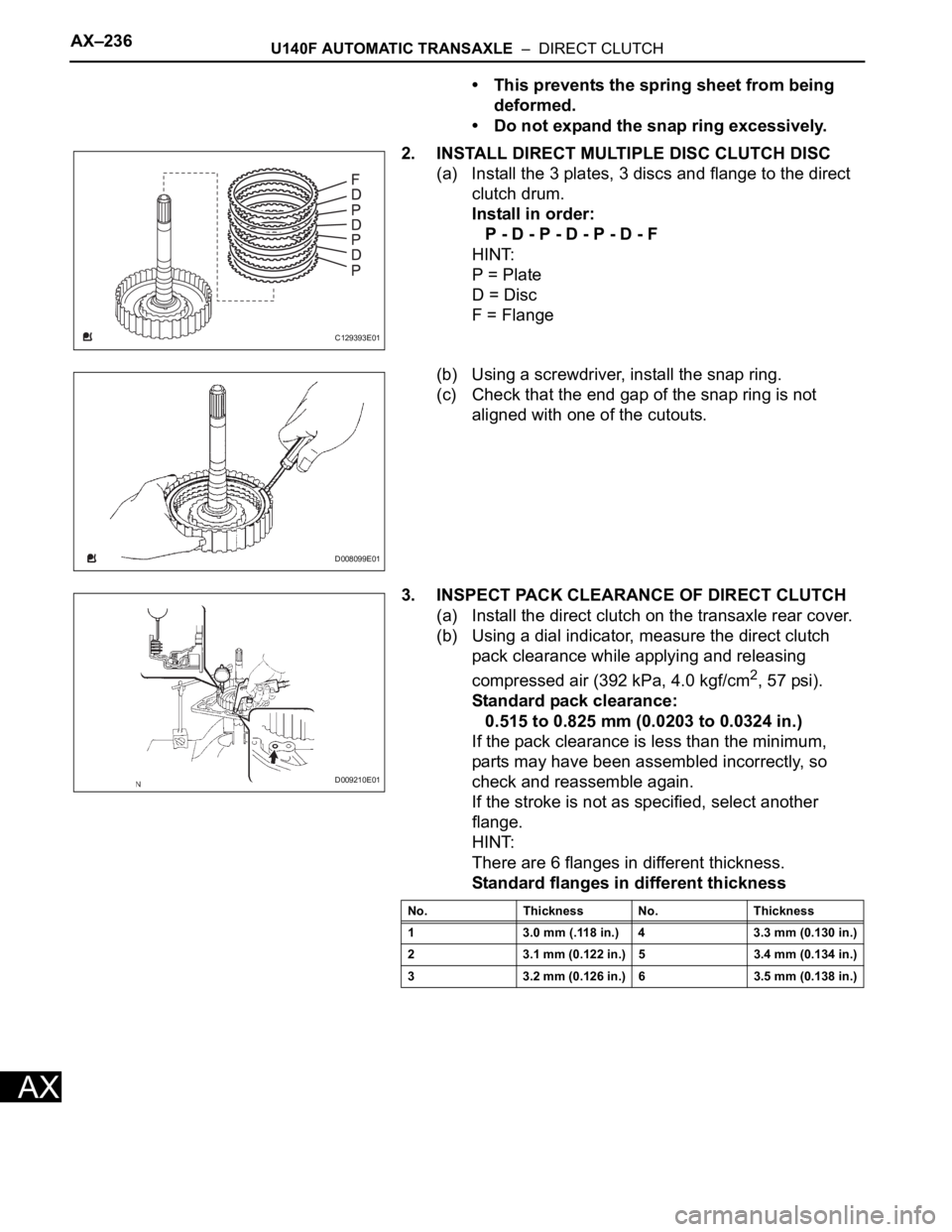
2. INSTALL DIRECT MULTIPLE DISC CLUTCH DISC
(a) Install the 3 plates, 3 discs and flange to the direct
clutch drum.
Install in order:
P - D - P - D - P - D - F
HINT:
P = Plate
D = Disc
F = Flange
(b) Using a screwdriver, install the snap ring.
(c) Check that the end gap of the snap ring is not
aligned with one of the cutouts.
3. INSPECT PACK CLEARANCE OF DIRECT CLUTCH
(a) Install the direct clutch on the transaxle rear cover.
(b) Using a dial indicator, measure the direct clutch
pack clearance while applying and releasing
compressed air (392 kPa, 4.0 kgf/cm
2, 57 psi).
Standard pack clearance:
0.515 to 0.825 mm (0.0203 to 0.0324 in.)
If the pack clearance is less than the minimum,
parts may have been assembled incorrectly, so
check and reassemble again.
If the stroke is not as specified, select another
flange.
HINT:
There are 6 flanges in different thickness.
Standard flanges in different thickness
C129393E01
D008099E01
D009210E01
No. Thickness No. Thickness
1 3.0 mm (.118 in.) 4 3.3 mm (0.130 in.)
2 3.1 mm (0.122 in.) 5 3.4 mm (0.134 in.)
3 3.2 mm (0.126 in.) 6 3.5 mm (0.138 in.)
Page 1427 of 2000
DIFFERENTIAL – REAR DIFFERENTIAL CARRIER ASSEMBLYDF–23
DF
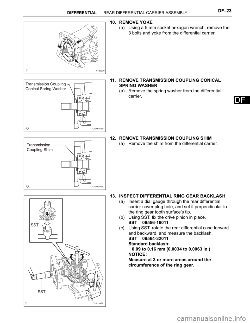
10. REMOVE YOKE
(a) Using a 5 mm socket hexagon wrench, remove the
3 bolts and yoke from the differential carrier.
11. REMOVE TRANSMISSION COUPLING CONICAL
SPRING WASHER
(a) Remove the spring washer from the differential
carrier.
12. REMOVE TRANSMISSION COUPLING SHIM
(a) Remove the shim from the differential carrier.
13. INSPECT DIFFERENTIAL RING GEAR BACKLASH
(a) Insert a dial gauge through the rear differential
carrier cover plug hole, and set it perpendicular to
the ring gear tooth surface's tip.
(b) Using SST, fix the drive pinion in place.
SST 09556-16011
(c) Using SST, rotate the rear differential case forward
and backward, and measure the backlash.
SST 09564-32011
Standard backlash:
0.09 to 0.16 mm (0.0034 to 0.0063 in.)
NOTICE:
Measure at 3 or more areas around the
circumference of the ring gear.
C129930
C109021E01
C109022E01
C110134E01
Page 1445 of 2000
DIFFERENTIAL – REAR DIFFERENTIAL CARRIER ASSEMBLYDF–41
DF
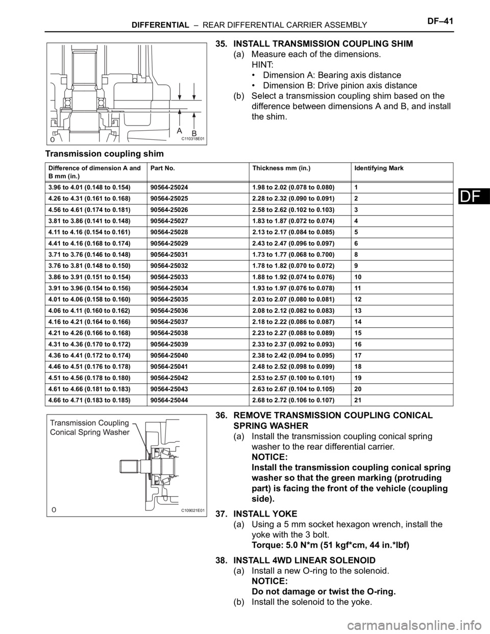
35. INSTALL TRANSMISSION COUPLING SHIM
(a) Measure each of the dimensions.
HINT:
• Dimension A: Bearing axis distance
• Dimension B: Drive pinion axis distance
(b) Select a transmission coupling shim based on the
difference between dimensions A and B, and install
the shim.
Transmission coupling shim
36. REMOVE TRANSMISSION COUPLING CONICAL
SPRING WASHER
(a) Install the transmission coupling conical spring
washer to the rear differential carrier.
NOTICE:
Install the transmission coupling conical spring
washer so that the green marking (protruding
part) is facing the front of the vehicle (coupling
side).
37. INSTALL YOKE
(a) Using a 5 mm socket hexagon wrench, install the
yoke with the 3 bolt.
Torque: 5.0 N*m (51 kgf*cm, 44 in.*lbf)
38. INSTALL 4WD LINEAR SOLENOID
(a) Install a new O-ring to the solenoid.
NOTICE:
Do not damage or twist the O-ring.
(b) Install the solenoid to the yoke.
C110318E01
Difference of dimension A and
B mm (in.)Part No. Thickness mm (in.) Identifying Mark
3.96 to 4.01 (0.148 to 0.154) 90564-25024 1.98 to 2.02 (0.078 to 0.080) 1
4.26 to 4.31 (0.161 to 0.168) 90564-25025 2.28 to 2.32 (0.090 to 0.091) 2
4.56 to 4.61 (0.174 to 0.181) 90564-25026 2.58 to 2.62 (0.102 to 0.103) 3
3.81 to 3.86 (0.141 to 0.148) 90564-25027 1.83 to 1.87 (0.072 to 0.074) 4
4.11 to 4.16 (0.154 to 0.161) 90564-25028 2.13 to 2.17 (0.084 to 0.085) 5
4.41 to 4.16 (0.168 to 0.174) 90564-25029 2.43 to 2.47 (0.096 to 0.097) 6
3.71 to 3.76 (0.146 to 0.148) 90564-25031 1.73 to 1.77 (0.068 to 0.700) 8
3.76 to 3.81 (0.148 to 0.150) 90564-25032 1.78 to 1.82 (0.070 to 0.072) 9
3.86 to 3.91 (0.151 to 0.154) 90564-25033 1.88 to 1.92 (0.074 to 0.076) 10
3.91 to 3.96 (0.154 to 0.156) 90564-25034 1.93 to 1.97 (0.076 to 0.078) 11
4.01 to 4.06 (0.158 to 0.160) 90564-25035 2.03 to 2.07 (0.080 to 0.081) 12
4.06 to 4.11 (0.160 to 0.162) 90564-25036 2.08 to 2.12 (0.082 to 0.083) 13
4.16 to 4.21 (0.164 to 0.166) 90564-25037 2.18 to 2.22 (0.086 to 0.087) 14
4.21 to 4.26 (0.166 to 0.168) 90564-25038 2.23 to 2.27 (0.088 to 0.089) 15
4.31 to 4.36 (0.170 to 0.172) 90564-25039 2.33 to 2.37 (0.092 to 0.093) 16
4.36 to 4.41 (0.172 to 0.174) 90564-25040 2.38 to 2.42 (0.094 to 0.095) 17
4.46 to 4.51 (0.176 to 0.178) 90564-25041 2.48 to 2.52 (0.098 to 0.099) 18
4.51 to 4.56 (0.178 to 0.180) 90564-25042 2.53 to 2.57 (0.100 to 0.101) 19
4.61 to 4.66 (0.181 to 0.183) 90564-25043 2.63 to 2.67 (0.104 to 0.105) 20
4.66 to 4.71 (0.183 to 0.185) 90564-25044 2.68 to 2.72 (0.106 to 0.107) 21
C109021E01