2006 TOYOTA RAV4 Rear
[x] Cancel search: RearPage 24 of 2000

ENGINE - 2AZ-FE ENGINE
01NEG46Y
ArmatureSurface Commutator
Permanent Magnet
Brush
LengthEG-27
STARTING SYSTEM
1. General
A compact and lightweight PS (Planetary reduction-Segment conductor motor) type starter is used.
Because the PS type starter contains an armature that uses square-shaped conductors, and its surface
functions as a commutator, it has resulted in both improving its output torque and reducing its overall
length.
In place of the field coil used in the conventional type starter, the PS type starter uses two types of
permanent magnets: main magnets and interpolar magnets. The main magnets and interpolar magnets
have been efficiently arranged to increase the magnetic flux and to shorten the length of the yoke.
Specifications
Starter TypePS Type
Rating Output1.7 kW
Rating Voltage12 V
Length*1mm (in.)128 (5.04)
Weight g (lb)2950 (6.50)
Rotational Direction*2Counterclockwise
*1: Length from the mounted area to the rear end of the starter
*
2: Viewed from pinion side
Page 94 of 2000

ENGINE - 2GR-FE ENGINE
01NEG63Y
01MEG36Y
Generator
Stator
RotorRegulator
EB
IG
M
RLOL
Ignition Switch
ECM
Towing Package Models and Models with RSES
Other Models Generator
Rectifier
Stator
Rotor
ERegulatorB
IG
M
RLOL
Ignition Switch
ECM
Discharge
Warning Light
Discharge
Warning Light
EG-98
CHARGING SYSTEM
1. General
A compact and lightweight segment conductor type generator is used. For details of the segment conductor
type generator, see page EG-25.
Specification
ModelTowing PackageWith RSES*Others
Ty p eSC2SE0
Rated Voltage12 V12 V
Output Rated150 A100 A
*: Rear Seat Entertainment System
Wiring Diagram
Page 97 of 2000

ENGINE - 2GR-FE ENGINEEG-101
ENGINE CONTROL SYSTEM
1. General
The engine control system of the 2GR-FE engine has the following features.
System
Outline
SFI
(Sequential Multiport
Fuel Injection)
[See page EG-117]
An L-type SFI system detects the intake air mass with a hot-wire type air
flow meter.
ESA
(Electronic Spark
Advance)
Ignition timing is determined by the ECM based on signals from various
sensors. The ECM corrects ignition timing in response to engine
knocking.
This system selects the optimal ignition timing in accordance with the
signals received from the sensors and sends the (IGT) ignition signal to
the igniter.
ETCS-i
(Electronic Throttle
Control
System-intelligent)
[See page EG-118]
Optimally controls the throttle valve opening in accordance with the amount
of accelerator pedal effort and the condition of the engine and the vehicle.
Dual VVT-i
(Variable Valve
Timing-intelligent)
System
[See page EG-120]
Controls the intake and exhaust camshafts to an optimal valve timing in
accordance with the engine condition.
ACIS
(Acoustic Control
Induction System)
[See page EG-126]The intake air passages are switched according to the engine speed and
throttle valve opening angle to provided high performance in all speed
ranges.
Air Intake Control
System
[See page EG-128]The intake air duct is divided into two areas, and the ECM controls the air
intake control valve and the actuator that are provided in one of the areas to
reduce the amount of engine noise.
Fuel Pump Control
[See page EG-53 in
2AZ-FE section]Fuel pump operation is controlled by signals from the ECM.
The fuel pump is stopped, when the SRS airbag is deployed in a frontal,
side, and rear side collision.
Air Conditioning Cut-off
ControlBy turning the air conditioning compressor ON or OFF in accordance with
the engine condition, drivability is maintained.
Charging Control
[See page EG-65 in
2AZ-FE section]The engine ECU regulates the charging voltage of the generator in
accordance with the driving conditions and the charging state of the battery.
Cooling Fan Control
[See page EG-129]
The cooling fan ECU steplessly controls the speed of the fans in accordance
with the engine coolant temperature, vehicle speed, engine speed, and air
conditioning operating conditions. As a result, the cooling performance is
improved.
(Continued)
Page 133 of 2000

CHASSIS - 4WD SYSTEM CH-66
4WD SYSTEM
DESCRIPTION
The 4WD system of the ’06 RAV4 uses an active torque control 4WD system.
It is a compact, lightweight, and high performance 4WD system that optimally controls the torque
distribution to the front and rear wheels through the electric control coupling in the rear differential.
ACTIVE TORQUE CONTROL 4WD SYSTEM
1. General
Based on information provided by various sensors, the 4WD ECU controls the amperage that is applied
to the electric control coupling, in order to transmit drive torque to the rear wheels when needed, and in
the amount needed. The following describes the features of the active torque control 4WD system.
Traction performance
Realizes stable start-off and acceleration performance
Driving stability performanceRealizes stable cornering performance
Fuel economyRealizes better fuel economy by transmitting drive torque to the rear
wheels when needed, in the amount needed.
A four-wheel drive lock switch has been provided. This enables the driver to select between the AUTO
and LOCK modes by operating the switch. The system optimally controls the torque distribution to the
front and rear wheels in the respective modes.
Mode
Four-wheel Drive
Lock Switch and
Indicator Light
Outline
AUTOOFF
Optimally distributes drive torque to the front and rear wheels.
Ensures optimal start-off performance during a start-off, based on
information provided by various sensors.
Suppresses the tight corner braking phenomenon* during low-speed
cornering.
Reduces the amount of torque distribution to the rear wheels and
improves fuel economy when the system judges that the vehicle is
traveling steadily.
Disengages the 4WD during braking deceleration.
LOCKON
Distributes the maximum torque limit to the rear wheels.
Distributes the maximum torque limit to the rear wheels during
start-off.
Distributes optimal torque during low-speed cornering.
Disengages the 4WD during braking deceleration.
Disengages the LOCK mode and transfers to the AUTO mode when
the vehicle speed exceeds 40 km / h (25 mph).
*: Tight corner braking phenomenon: a condition in which the brakes are applied due to a rotational difference
between the front and rear wheels, such as during low-speed cornering in the 4WD mode.
The 4WD ECU effects cooperative control with the skid control ECU, in order to control the drive torque
distribution to the front and rear wheels in accordance with information received from the skid control
ECU. These controls ensure a smooth acceleration and driving stability.
Page 137 of 2000

CHASSIS - 4WD SYSTEM
01NCH38Y
Torque Distribution
to Rear WheelsTorque Distribution
to Rear Wheels
Straightline Driving Low-Speed Cornering
01NCH39Y
Torque Distribution
to Rear WheelsTorque Distribution
to Rear Wheels
Steady Driving Straightline Acceleration
NOTICE
In the LOCK mode after the four-wheel drive lock switch is pressed, the system starts control upon
judging that the vehicle is operating in a stable manner. During this judgment, the 4WD LOCK
indicator light blinks.
CH-70
5. System Operation
Auto Mode
1) Starting Off
The system ensures start-off performance by optimally distributing the entire drive torque, which is
transmitted by the engine, to the front and rear wheels.
To prevent the tight corner braking phenomenon from occurring during low-speed cornering, the
system reduces the amount of torque distribution to the rear wheels.
2) Normal Driving
During normal driving, when the system judges that the vehicle is traveling steadily, it reduces the
amount of torque distribution to the rear wheels. This allows the vehicle to operate in conditions
similar to front-wheel-drive, which improves fuel economy.
To ensure excellent acceleration performance during straightline acceleration and excellent driving
stability during cornering, the system controls the amount of torque distribution to the rear wheels.
Lock Mode
When the vehicle is in a situation that poses difficulty for it to pull itself out, such as sand, the driver can
switch to LOCK mode by operating the four-wheel drive lock switch. Thus, this mode effects optimal
control in accordance with the driving conditions and transmits as much drive torque as possible to the rear
wheels, in a mode that is similar to the locked 4WD mode.
Page 167 of 2000

IN–22INTRODUCTION – REPAIR INSTRUCTION
IN
VEHICLE LIFT AND SUPPORT
LOCATIONS
1. NOTICE ABOUT VEHICLE CONDITION WHEN
JACKING UP VEHICLE
(a) The vehicle must be unloaded before jacking up /
lifting up the vehicle. Never jack up / lift up a heavily
loaded vehicle.
(b) When removing heavy parts such as the engine and
transmission, the center of gravity of the vehicle
may shift. To stabilize the vehicle, place a balance
weight in a location where it will not roll or shift, or
use a mission jack to hold the jacking support.
2. NOTICE FOR USING 4 POST LIFT
(a) Follow the safety procedures outlined in the lift
instruction manual.
(b) Use precautionary measures to prevent the free
wheel beam from damaging tires or wheels.
(c) Use wheel chocks to secure the vehicle.
3. NOTICE FOR USING JACK AND SAFETY STAND
(a) Work on a level surface. Use wheel chocks at all
times.
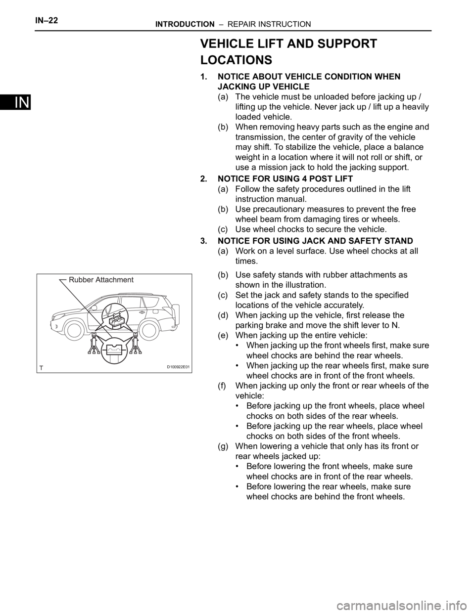
(b) Use safety stands with rubber attachments as
shown in the illustration.
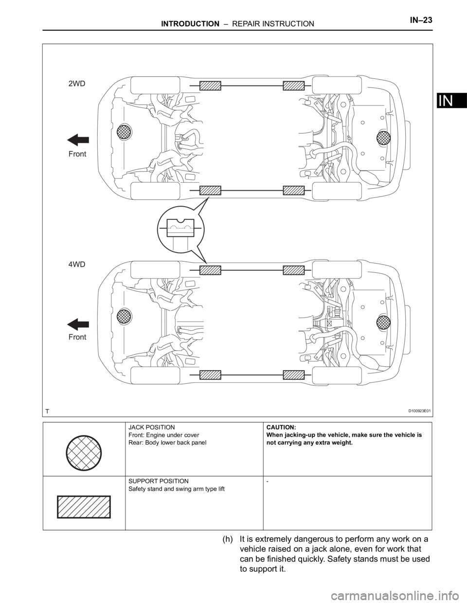
(c) Set the jack and safety stands to the specified
locations of the vehicle accurately.
(d) When jacking up the vehicle, first release the
parking brake and move the shift lever to N.
(e) When jacking up the entire vehicle:
• When jacking up the front wheels first, make sure
wheel chocks are behind the rear wheels.
• When jacking up the rear wheels first, make sure
wheel chocks are in front of the front wheels.
(f) When jacking up only the front or rear wheels of the
vehicle:
• Before jacking up the front wheels, place wheel
chocks on both sides of the rear wheels.
• Before jacking up the rear wheels, place wheel
chocks on both sides of the front wheels.
(g) When lowering a vehicle that only has its front or
rear wheels jacked up:
• Before lowering the front wheels, make sure
wheel chocks are in front of the rear wheels.
• Before lowering the rear wheels, make sure
wheel chocks are behind the front wheels.
D100922E01
Page 168 of 2000

INTRODUCTION – REPAIR INSTRUCTIONIN–23
IN
(h) It is extremely dangerous to perform any work on a
vehicle raised on a jack alone, even for work that
can be finished quickly. Safety stands must be used
to support it.
JACK POSITION
Front: Engine under cover
Rear: Body lower back panelCAUTION:
When jacking-up the vehicle, make sure the vehicle is
not carrying any extra weight.
SUPPORT POSITION
Safety stand and swing arm type lift-
D100923E01
Page 170 of 2000

INTRODUCTION – REPAIR INSTRUCTIONIN–25
IN
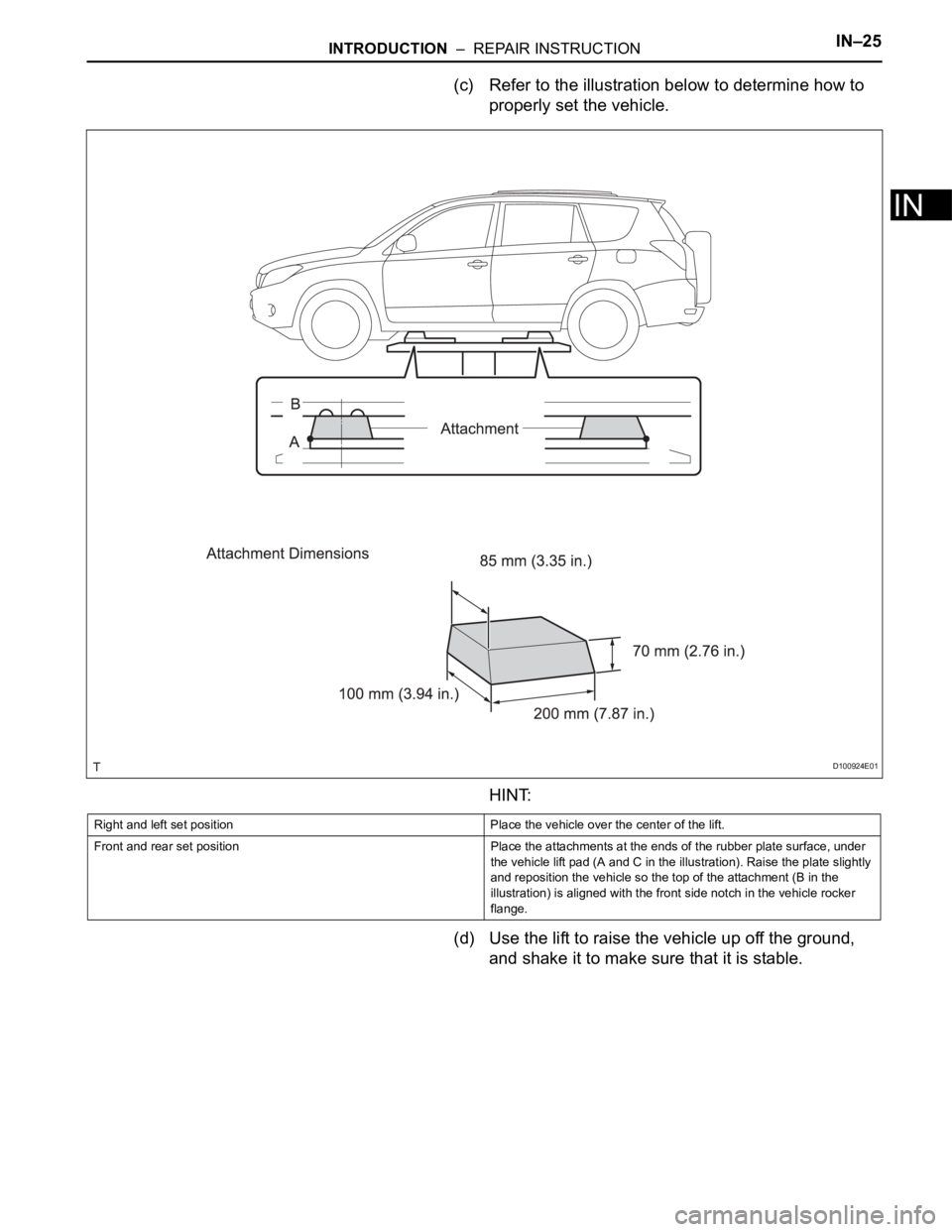
(c) Refer to the illustration below to determine how to
properly set the vehicle.
HINT:
(d) Use the lift to raise the vehicle up off the ground,
and shake it to make sure that it is stable.
D100924E01
Right and left set position Place the vehicle over the center of the lift.
Front and rear set position Place the attachments at the ends of the rubber plate surface, under
the vehicle lift pad (A and C in the illustration). Raise the plate slightly
and reposition the vehicle so the top of the attachment (B in the
illustration) is aligned with the front side notch in the vehicle rocker
flange.