2006 TOYOTA RAV4 Brake system
[x] Cancel search: Brake systemPage 1341 of 2000

GF1A TRANSFER – ACTIVE TORQUE CONTROL 4WD SYSTEMTF–13
TF
TEST MODE PROCEDURE
1. DESCRIPTION
HINT:
When using a chassis dynamometer, brake tester, etc. to
perform a vehicle test, activate test mode to avoid a
"different tire diameter installed" incorrect judgment.
Test mode does not have a 4WD parameter. Test mode
is activated because it will prohibit a different tire
diameter judgment.
2. ACTIVATE TEST MODE
HINT:
Activate test mode before using a chassis dynamometer,
brake tester, etc. to perform a vehicle test.
(a) Check that the ignition switch is OFF.
(b) Use either of the following methods to change the
4WD ECU to test mode.
(1) Test mode activation through intelligent tester
(with CAM VIM).
• Connect the intelligent tester (with CAM VIM)
to the DLC3 connector and turn the ignition
switch ON. Using the test mode activation
function (mode 10), activate test mode.
(2) Test mode activation by shorting TS terminal
• With the ignition switch OFF, short-circuit the
TS and CG terminals of the DLC3 connector.
Then turn the ignition switch ON to activate
test mode.
NOTICE:
When the ignition switch is turned from
OFF to ON, the 4WD indicator light will
illuminate for 4 seconds. Then it will turn
off.
4WD Lock Mode indicator
HINT:
When the ignition switch is ON and the 4WD
lock switch is turned from OFF to ON, the
4WD lock mode indicator blinks twice and
then illuminates.
If the indicator does not illuminate, check the
bulb for burnout. Also, inspect the wire
harness between the 4WD ECU and
combination meter.
Control Status 4WD Control Status
During test mode Different tire diameter malfunction judgment (detection that tire
diameter of 4 wheels are not same) is not performed.
Other than above item, normal control is performed.
- 4WD lock switch OFF (4WD auto mode status)
- 4WD lock switch ON (4WD lock mode status)
4WD Lock Switch OFF Illuminates for 4 seconds, then turns
OFF
4WD Lock Switch ON Remains illuminated
Page 1343 of 2000

GF1A TRANSFER – ACTIVE TORQUE CONTROL 4WD SYSTEMTF–15
TF
PROBLEM SYMPTOMS TABLE
HINT:
• Use the table below to help determine the cause of the
problem symptom. The potential causes of the symptoms
are listed in order of probability in the "Suspected area"
column of the table. Check each symptom by checking the
suspected areas in the order they are listed. Replace parts
as necessary.
• Inspect the fuses and relays related to this system before
inspecting the suspected areas below.
Active torque control 4WD system
HINT:
*:When driving 4WD mode, the vehicle is hard to turn, as if
the brakes were applied, due to the rotational difference
between the front and rear tires while turning.
Symptom Suspected area See page
Phenomenon of tight-corner braking*1.Steering angle sensor circuitTF-27
2.Linear solenoid circuitTF-30
3.4WD control ECU
4WD indicator light remains ON 4WD indicator light circuitTF-36
4WD indicator light does not come ON 4WD indicator light circuitTF-40
The system is in the DTC output mode although
terminals TC and CG of the DLC3 are not short
circuited1.TC and CG terminal circuitTF-42
2.4WD indicator light circuit
The system is not in the DTC output mode although
terminals TC and CG of the DLC3 are not short
circuited1.TC and CG terminal circuitTF-42
2.4WD indicator light circuit
Page 1347 of 2000
GF1A TRANSFER – ACTIVE TORQUE CONTROL 4WD SYSTEMTF–19
TF
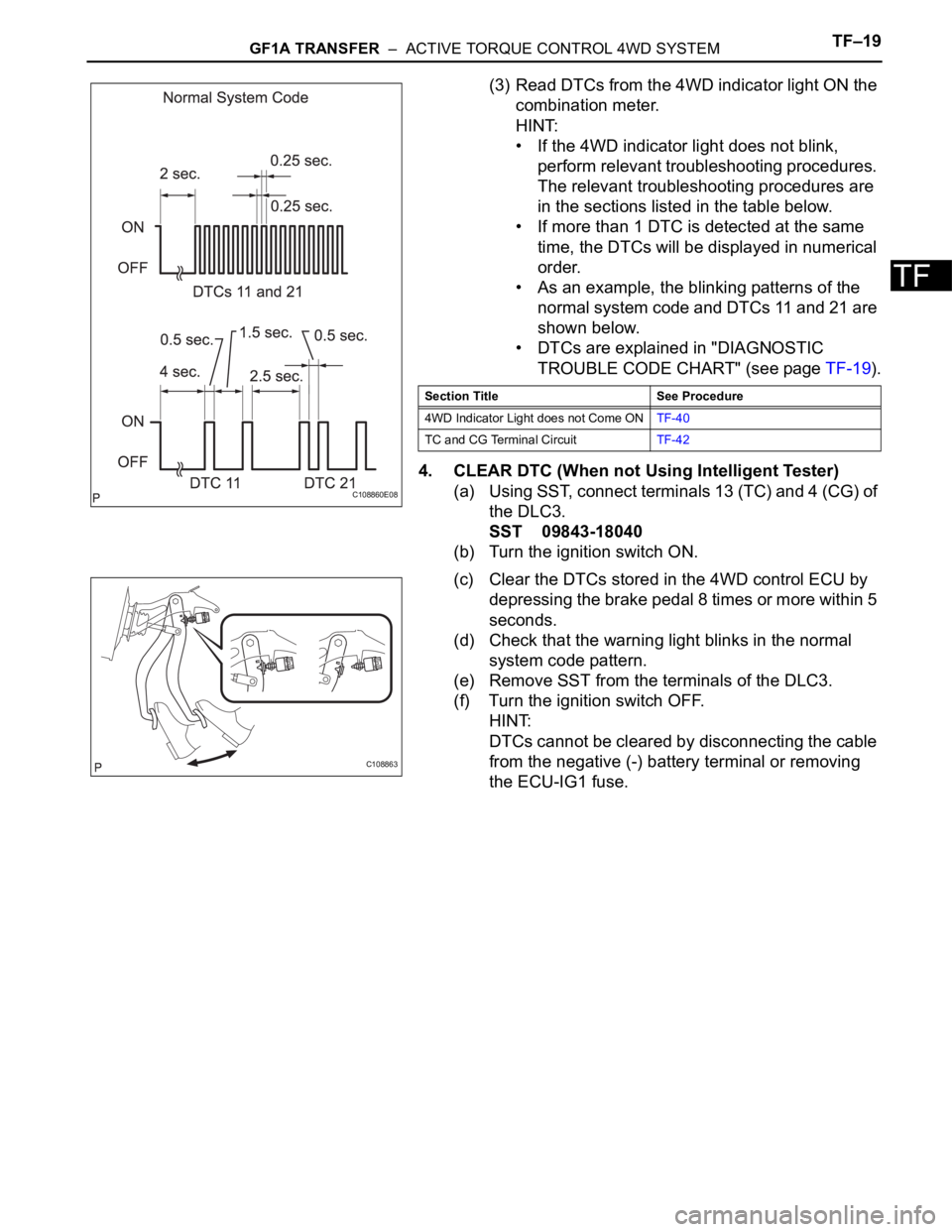
(3) Read DTCs from the 4WD indicator light ON the
combination meter.
HINT:
• If the 4WD indicator light does not blink,
perform relevant troubleshooting procedures.
The relevant troubleshooting procedures are
in the sections listed in the table below.
• If more than 1 DTC is detected at the same
time, the DTCs will be displayed in numerical
order.
• As an example, the blinking patterns of the
normal system code and DTCs 11 and 21 are
shown below.
• DTCs are explained in "DIAGNOSTIC
TROUBLE CODE CHART" (see page TF-19).
4. CLEAR DTC (When not Using Intelligent Tester)
(a) Using SST, connect terminals 13 (TC) and 4 (CG) of
the DLC3.
SST 09843-18040
(b) Turn the ignition switch ON.
(c) Clear the DTCs stored in the 4WD control ECU by
depressing the brake pedal 8 times or more within 5
seconds.
(d) Check that the warning light blinks in the normal
system code pattern.
(e) Remove SST from the terminals of the DLC3.
(f) Turn the ignition switch OFF.
HINT:
DTCs cannot be cleared by disconnecting the cable
from the negative (-) battery terminal or removing
the ECU-IG1 fuse.
C108860E08
Section Title See Procedure
4WD Indicator Light does not Come ONTF-40
TC and CG Terminal CircuitTF-42
C108863
Page 1349 of 2000

GF1A TRANSFER – ACTIVE TORQUE CONTROL 4WD SYSTEMTF–21
TF
DATA LIST / ACTIVE TEST
1. READ DATA LIST
HINT:
Using the intelligent tester's (with CAN VIM) DATA LIST
allows switch, sensor and other item values to be read
without removing any parts. Reading the DATA LIST
early in troubleshooting is one way to save time.
(a) Connect the intelligent tester (with CAN VIM) to the
DLC3.
(b) Turn the ignition switch ON.
(c) Read the DATA LIST according to the display on the
tester.
4WD control ECU
Item Measurement Item/Range
(Display)Normal Condition Diagnostic Note
4WD WARN LAMP 4WD indicator light /OFF or ON OFF: 4WD indicator light OFF
ON: 4WD indicator light ON-
SLIP INDI LAMP Slip indicator light /OFF or ON OFF: SLIP indicator light OFF
ON: SLIP indicator light ON-
STOP LAMP SW Stop light switch /OFF or ON OFF: Brake pedal released
ON: Brake pedal depressed-
STEERING ANGLE Steering angle value /
Min.: -3276.8 deg
Max.: 3276.7 degMin.: -3276.8 deg
Max.: 3276.7 deg-
FR WHEEL SPD FR wheel speed /
Min.: 0 km/h (0 mph)
Reading : Max.: 326.4 km/h
(202.8 mph)Actual wheel speed Almost no difference from the
speedometer
FL WHEEL SPD FL wheel speed /
Min.: 0 km/h (0 mph)
Reading : Max.: 326.4 km/h
(202.8 mph)Actual wheel speed Almost no difference from the
speedometer
RR WHEEL SPD RR wheel speed /
Min.: 0 km/h (0 mph)
Reading : Max.: 326.4 km/h
(202.8 mph)Actual wheel speed Almost no difference from the
speedometer
RLWHEEL SPD RL wheel speed /
Min.: 0 km/h (0 mph)
Reading : Max.: 326.4 km/h
(202.8 mph)Actual wheel speed Almost no difference from the
speedometer
AMBI TEMP Ambient temperature /
Min.: -128
C (198.4 F)
Max.: 127 C (260.6 F)Min.: -128 (198.4
F)
Max.: 127 (260.6
F)-
COOLANT TEMP Engine coolant temperature /
Min.: 0
C (32 F)
Max.: 127.5
C (261.5 F)Min.: 0
C (32 F)
Max.: 127.5 C (261.5 F)-
LOCK SW 4WD lock switch / OFF or ON OFF: 4WD lock switch off
ON: 4WD lock switch on-
SLC CUR SLC solenoid (4WD linear
solenoid) current /
Min.: 0 A
Max.: 3 AMin.: 0 A
Max.: 3 A-
Page 1351 of 2000
GF1A TRANSFER – ACTIVE TORQUE CONTROL 4WD SYSTEMTF–23
TF
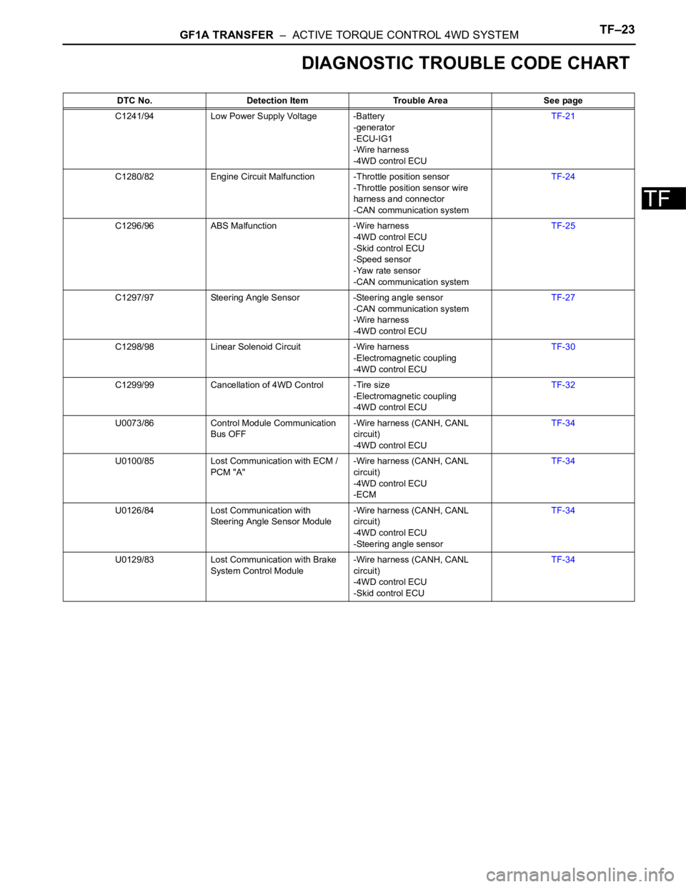
DIAGNOSTIC TROUBLE CODE CHART
DTC No. Detection Item Trouble Area See page
C1241/94 Low Power Supply Voltage -Battery
-generator
-ECU-IG1
-Wire harness
-4WD control ECUTF-21
C1280/82 Engine Circuit Malfunction -Throttle position sensor
-Throttle position sensor wire
harness and connector
-CAN communication systemTF-24
C1296/96 ABS Malfunction -Wire harness
-4WD control ECU
-Skid control ECU
-Speed sensor
-Yaw rate sensor
-CAN communication systemTF-25
C1297/97 Steering Angle Sensor -Steering angle sensor
-CAN communication system
-Wire harness
-4WD control ECUTF-27
C1298/98 Linear Solenoid Circuit -Wire harness
-Electromagnetic coupling
-4WD control ECUTF-30
C1299/99 Cancellation of 4WD Control -Tire size
-Electromagnetic coupling
-4WD control ECUTF-32
U0073/86 Control Module Communication
Bus OFF-Wire harness (CANH, CANL
circuit)
-4WD control ECUTF-34
U0100/85 Lost Communication with ECM /
PCM "A"-Wire harness (CANH, CANL
circuit)
-4WD control ECU
-ECMTF-34
U0126/84 Lost Communication with
Steering Angle Sensor Module-Wire harness (CANH, CANL
circuit)
-4WD control ECU
-Steering angle sensorTF-34
U0129/83 Lost Communication with Brake
System Control Module-Wire harness (CANH, CANL
circuit)
-4WD control ECU
-Skid control ECUTF-34
Page 1353 of 2000
GF1A TRANSFER – ACTIVE TORQUE CONTROL 4WD SYSTEMTF–25
TF
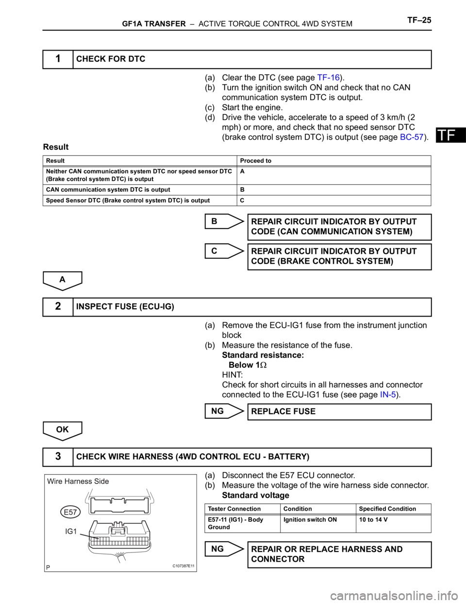
(a) Clear the DTC (see page TF-16).
(b) Turn the ignition switch ON and check that no CAN
communication system DTC is output.
(c) Start the engine.
(d) Drive the vehicle, accelerate to a speed of 3 km/h (2
mph) or more, and check that no speed sensor DTC
(brake control system DTC) is output (see page BC-57).
Result
B
C
A
(a) Remove the ECU-IG1 fuse from the instrument junction
block
(b) Measure the resistance of the fuse.
Standard resistance:
Below 1
HINT:
Check for short circuits in all harnesses and connector
connected to the ECU-IG1 fuse (see page IN-5).
NG
OK
(a) Disconnect the E57 ECU connector.
(b) Measure the voltage of the wire harness side connector.
Standard voltage
NG
1CHECK FOR DTC
Result Proceed to
Neither CAN communication system DTC nor speed sensor DTC
(Brake control system DTC) is outputA
CAN communication system DTC is output B
Speed Sensor DTC (Brake control system DTC) is output C
REPAIR CIRCUIT INDICATOR BY OUTPUT
CODE (CAN COMMUNICATION SYSTEM)
REPAIR CIRCUIT INDICATOR BY OUTPUT
CODE (BRAKE CONTROL SYSTEM)
2INSPECT FUSE (ECU-IG)
REPLACE FUSE
3CHECK WIRE HARNESS (4WD CONTROL ECU - BATTERY)
C107387E11
Tester Connection Condition Specified Condition
E57-11 (IG1) - Body
GroundIgnition switch ON 10 to 14 V
REPAIR OR REPLACE HARNESS AND
CONNECTOR
Page 1356 of 2000
TF–28GF1A TRANSFER – ACTIVE TORQUE CONTROL 4WD SYSTEM
TF
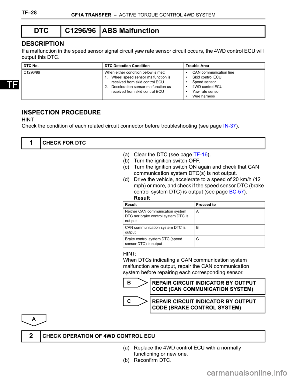
DESCRIPTION
If a malfunction in the speed sensor signal circuit yaw rate sensor circuit occurs, the 4WD control ECU will
output this DTC.
INSPECTION PROCEDURE
HINT:
Check the condition of each related circuit connector before troubleshooting (see page IN-37).
(a) Clear the DTC (see page TF-16).
(b) Turn the ignition switch OFF.
(c) Turn the ignition switch ON again and check that CAN
communication system DTC(s) is not output.
(d) Drive the vehicle, accelerate to a speed of 20 km/h (12
mph) or more, and check if the speed sensor DTC (brake
control system DTC) is output (see page BC-57).
Result
HINT:
When DTCs indicating a CAN communication system
malfunction are output, repair the CAN communication
system before repairing each corresponding sensor.
B
C
A
(a) Replace the 4WD control ECU with a normally
functioning or new one.
(b) Reconfirm DTC.
DTC C1296/96 ABS Malfunction
DTC No. DTC Detection Condition Trouble Area
C1296/96 When either condition below is met:
1. Wheel speed sensor malfunction is
received from skid control ECU
2. Deceleration sensor malfunction us
received from skid control ECU• CAN communication line
• Skid control ECU
• Speed sensor
• 4WD control ECU
• Yaw rate sensor
• Wire harness
1CHECK FOR DTC
Result Proceed to
Neither CAN communication system
DTC nor brake control system DTC is
out putA
CAN communication system DTC is
outputB
Brake control system DTC (speed
sensor DTC) is outputC
REPAIR CIRCUIT INDICATOR BY OUTPUT
CODE (CAN COMMUNICATION SYSTEM)
REPAIR CIRCUIT INDICATOR BY OUTPUT
CODE (BRAKE CONTROL SYSTEM)
2CHECK OPERATION OF 4WD CONTROL ECU
Page 1357 of 2000
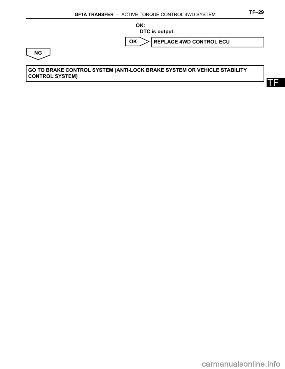
GF1A TRANSFER – ACTIVE TORQUE CONTROL 4WD SYSTEMTF–29
TF
OK:
DTC is output.
OK
NGREPLACE 4WD CONTROL ECU
GO TO BRAKE CONTROL SYSTEM (ANTI-LOCK BRAKE SYSTEM OR VEHICLE STA B I L I T Y
CONTROL SYSTEM)