Page 1625 of 2000

POWER STEERING – ELECTRONIC POWER STEERING SYSTEMPS–25
PS
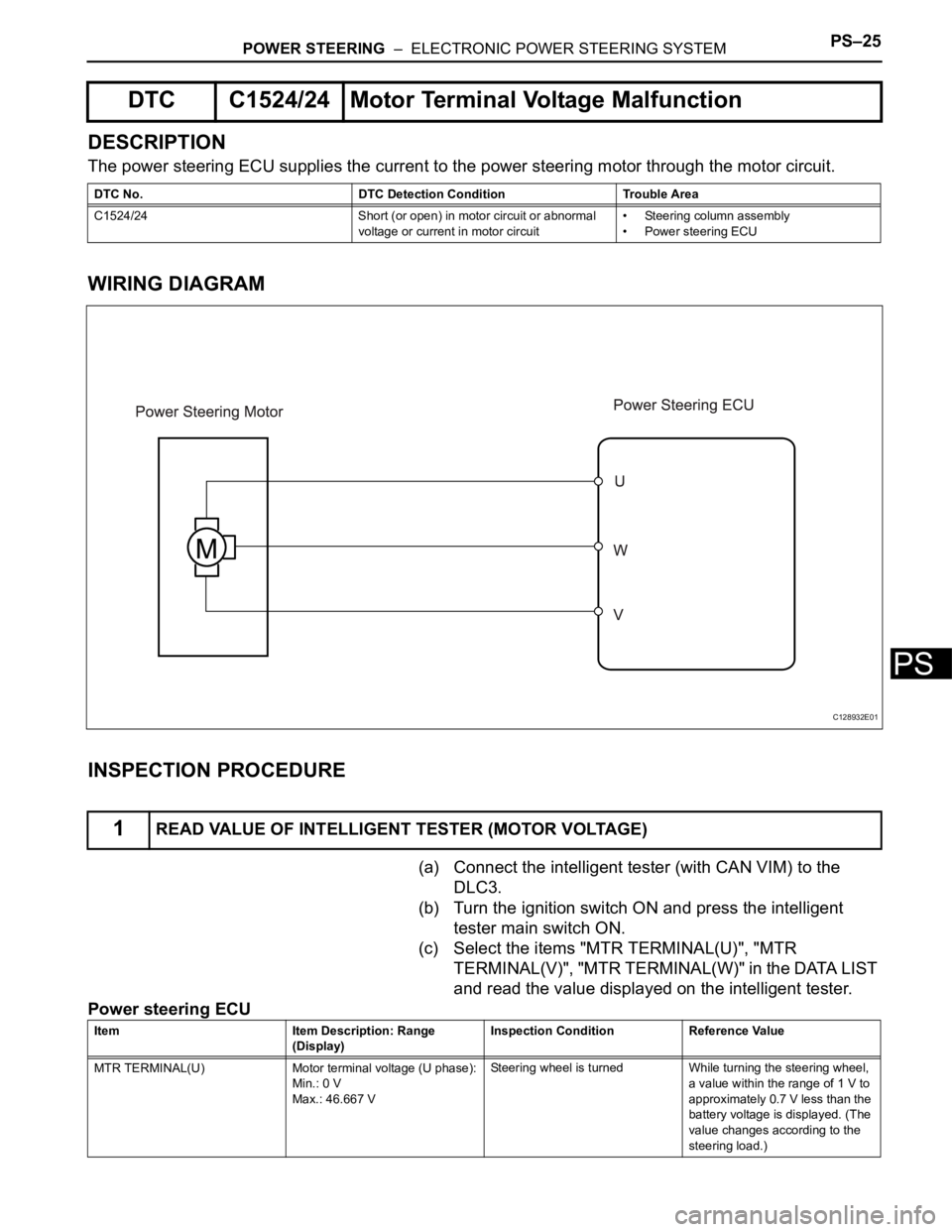
DESCRIPTION
The power steering ECU supplies the current to the power steering motor through the motor circuit.
WIRING DIAGRAM
INSPECTION PROCEDURE
(a) Connect the intelligent tester (with CAN VIM) to the
DLC3.
(b) Turn the ignition switch ON and press the intelligent
tester main switch ON.
(c) Select the items "MTR TERMINAL(U)", "MTR
TERMINAL(V)", "MTR TERMINAL(W)" in the DATA LIST
and read the value displayed on the intelligent tester.
Power steering ECU
DTC C1524/24 Motor Terminal Voltage Malfunction
DTC No. DTC Detection Condition Trouble Area
C1524/24 Short (or open) in motor circuit or abnormal
voltage or current in motor circuit• Steering column assembly
• Power steering ECU
1READ VALUE OF INTELLIGENT TESTER (MOTOR VOLTAGE)
C128932E01
Item Item Description: Range
(Display)Inspection Condition Reference Value
MTR TERMINAL(U) Motor terminal voltage (U phase):
Min.: 0 V
Max.: 46.667 VSteering wheel is turned While turning the steering wheel,
a value within the range of 1 V to
approximately 0.7 V less than the
battery voltage is displayed. (The
value changes according to the
steering load.)
Page 1626 of 2000

PS–26POWER STEERING – ELECTRONIC POWER STEERING SYSTEM
PS
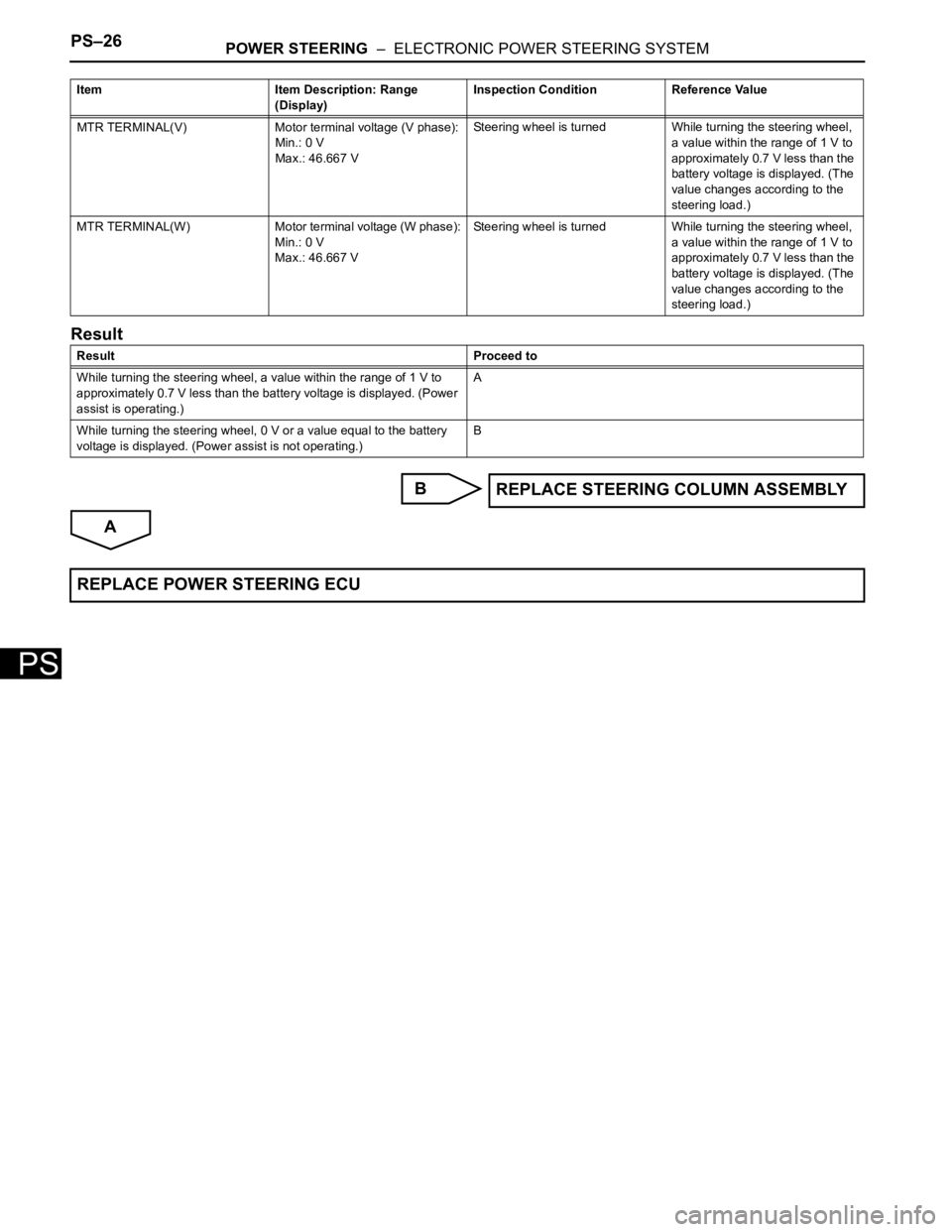
Result
B
A
MTR TERMINAL(V) Motor terminal voltage (V phase):
Min.: 0 V
Max.: 46.667 VSteering wheel is turned While turning the steering wheel,
a value within the range of 1 V to
approximately 0.7 V less than the
battery voltage is displayed. (The
value changes according to the
steering load.)
MTR TERMINAL(W) Motor terminal voltage (W phase):
Min.: 0 V
Max.: 46.667 VSteering wheel is turned While turning the steering wheel,
a value within the range of 1 V to
approximately 0.7 V less than the
battery voltage is displayed. (The
value changes according to the
steering load.)
Result Proceed to
While turning the steering wheel, a value within the range of 1 V to
approximately 0.7 V less than the battery voltage is displayed. (Power
assist is operating.)A
While turning the steering wheel, 0 V or a value equal to the battery
voltage is displayed. (Power assist is not operating.)B Item Item Description: Range
(Display)Inspection Condition Reference Value
REPLACE STEERING COLUMN ASSEMBLY
REPLACE POWER STEERING ECU
Page 1627 of 2000
POWER STEERING – ELECTRONIC POWER STEERING SYSTEMPS–27
PS
DESCRIPTION
The motor rotation angle sensor detects the motor rotation angle and sends this information to the power
steering ECU.
WIRING DIAGRAM
INSPECTION PROCEDURE
(a) Check the installation condition of the motor rotation
angle sensor connector.
OK:
Motor rotation angle sensor connector is securely
connected to the power steering ECU.
Result
DTC C1528/12 Motor Rotation Angle Sensor Malfunction
DTC No. DTC Detection Condition Trouble Area
C1528/12 Motor rotation angle sensor malfunction • Steering column assembly
• Power steering ECU
1CHECK CONNECTOR CONNECTION CONDITION
C128934E01
Result Proceed to
NG A
OK B
Page 1628 of 2000
PS–28POWER STEERING – ELECTRONIC POWER STEERING SYSTEM
PS
B
A
(a) Reinstall motor rotation angle sensor connector.
(b) Check for DTC.
OK:
DTC is not output.
Result
B
A
(a) Connect the intelligent tester (with CAN VIM) to the
DLC3.
(b) Turn the ignition switch ON and press the intelligent
tester main switch ON.
(c) Select the items "MOTOR ROTATE" in the DATA LIST
and read the value displayed on the intelligent tester.
OK:
During steering operation, motor rotation angle
value changes from 0 to 360
NG
OK Go to step 3
2RECONFIRM DTC
Result Proceed to
DTC is output A
DTC is not output B
END
3READ VALUE OF INTELLIGENT TESTER (MOTOR ROTATION ANGLE SENSOR)
Item Item Description: Range
(Display)Inspection Condition Reference Value
MOTOR ROTATE Motor Rotation Angle:
Min.: 0
Max.: 360
Steering wheel is turned During steering operation, motor
rotation angle value changes from
0 to 360
REPLACE STEERING COLUMN ASSEMBLY
REPLACE POWER STEERING ECU
Page 1884 of 2000
LI–134LIGHTING – HEADLIGHT DIMMER SWITCH
LI
REMOVAL
1. DISCONNECT CABLE FROM NEGATIVE BATTERY
TERMINAL
CAUTION:
Wait at least 90 seconds after disconnecting the
cable from the negative (-) battery terminal to
prevent airbag and seat belt pretensioner activation.
2. PLACE FRONT WHEELS FACING STRAIGHT AHEAD
3. REMOVE STEERING PAD ASSEMBLY (See page RS-
336)
4. REMOVE STEERING WHEEL ASSEMBLY (See page
SR-12)
5. REMOVE STEERING COLUMN COVER (See page
SR-12)
6. REMOVE SPIRAL CABLE SUB-ASSEMBLY (See page
RS-346)
7. REMOVE WIPER AND WASHER SWITCH (See page
WW-27)
8. REMOVE HEADLIGHT DIMMER SWITCH ASSEMBLY
(a) Disconnect the connector.
(b) Using needle-nose pliers, remove the band clamp
as shown in the illustration.
(c) Using a screwdriver, detach the claws and remove
the switch.
HINT:
Tape the screwdriver tip before use.
B088653
B088654
B088655E01
Page 1886 of 2000
LI–136LIGHTING – HEADLIGHT DIMMER SWITCH
LI
(b) Install the headlight dimmer switch with the clamp.
(c) Connect the connector.
2. INSTALL WIPER AND WASHER SWITCH ASSEMBLY
(See page WW-29)
3. INSTALL SPIRAL CABLE SUB-ASSEMBLY (See page
RS-347)
4. INSTALL STEERING COLUMN COVER (See page SR-
20)
5. INSTALL STEERING WHEEL ASSEMBLY (See page
SR-21)
6. PLACE FRONT WHEELS FACING STRAIGHT AHEAD
7. INSPECT STEERING WHEEL CENTER POINT
8. INSTALL STEERING PAD ASSEMBLY (See page RS-
336)
9. CONNECT CABLE TO NEGATIVE BATTERY
TERMINAL
10. INSPECT STEERING PAD ASSEMBLY (See page RS-
337)
11. CHECK SRS WARNING LIGHT
(a) Check the SRS warning light (see page RS-337).
B135620
B088653
Page 1896 of 2000

WIPER AND WASHER – WIPER SWITCHWW–27
WW
REMOVAL
1. DISCONNECT CABLE FROM NEGATIVE BATTERY
TERMINAL
CAUTION:
Wait at least 90 seconds after disconnecting the
cable from the negative (-) battery terminal to
prevent airbag and seat belt pretensioner activation.
2. PLACE FRONT WHEELS FACING STRAIGHT AHEAD
3. REMOVE STEERING PAD ASSEMBLY (See page RS-
336)
4. REMOVE STEERING WHEEL ASSEMBLY (See page
SR-12)
5. REMOVE STEERING COLUMN COVER UPPER (See
page SR-12)
6. REMOVE STEERING COLUMN COVER LOWER (See
page SR-12)
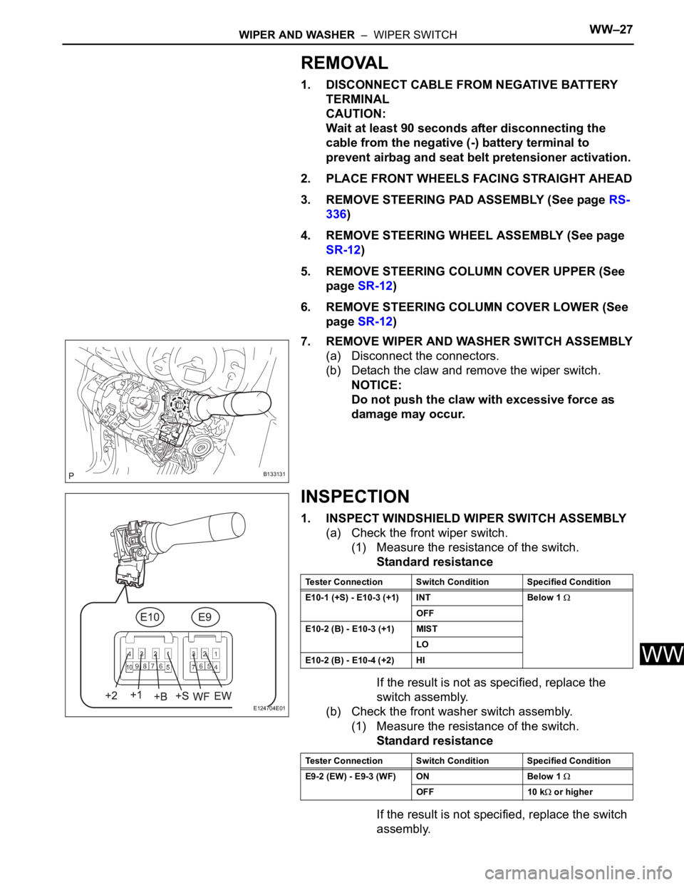
7. REMOVE WIPER AND WASHER SWITCH ASSEMBLY
(a) Disconnect the connectors.
(b) Detach the claw and remove the wiper switch.
NOTICE:
Do not push the claw with excessive force as
damage may occur.
INSPECTION
1. INSPECT WINDSHIELD WIPER SWITCH ASSEMBLY
(a) Check the front wiper switch.
(1) Measure the resistance of the switch.
Standard resistance
If the result is not as specified, replace the
switch assembly.
(b) Check the front washer switch assembly.
(1) Measure the resistance of the switch.
Standard resistance
If the result is not specified, replace the switch
assembly.
B133131
E124704E01
Tester Connection Switch Condition Specified Condition
E10-1 (+S) - E10-3 (+1) INT Below 1
OFF
E10-2 (B) - E10-3 (+1) MIST
LO
E10-2 (B) - E10-4 (+2) HI
Tester Connection Switch Condition Specified Condition
E9-2 (EW) - E9-3 (WF) ON Below 1
OFF 10 k or higher
Page 1898 of 2000

WIPER AND WASHER – WIPER SWITCHWW–29
WW
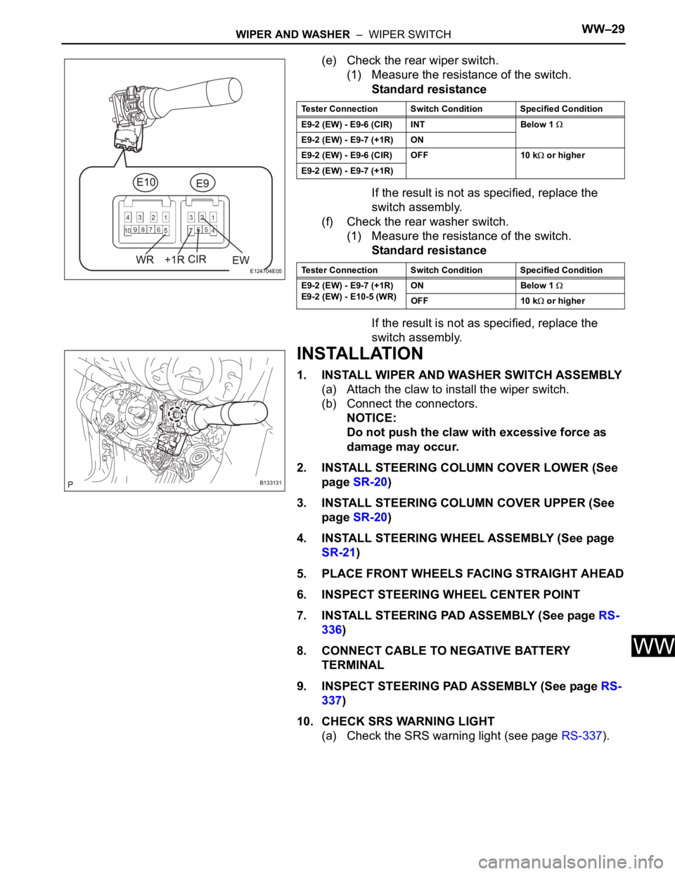
(e) Check the rear wiper switch.
(1) Measure the resistance of the switch.
Standard resistance
If the result is not as specified, replace the
switch assembly.
(f) Check the rear washer switch.
(1) Measure the resistance of the switch.
Standard resistance
If the result is not as specified, replace the
switch assembly.
INSTALLATION
1. INSTALL WIPER AND WASHER SWITCH ASSEMBLY
(a) Attach the claw to install the wiper switch.
(b) Connect the connectors.
NOTICE:
Do not push the claw with excessive force as
damage may occur.
2. INSTALL STEERING COLUMN COVER LOWER (See
page SR-20)
3. INSTALL STEERING COLUMN COVER UPPER (See
page SR-20)
4. INSTALL STEERING WHEEL ASSEMBLY (See page
SR-21)
5. PLACE FRONT WHEELS FACING STRAIGHT AHEAD
6. INSPECT STEERING WHEEL CENTER POINT
7. INSTALL STEERING PAD ASSEMBLY (See page RS-
336)
8. CONNECT CABLE TO NEGATIVE BATTERY
TERMINAL
9. INSPECT STEERING PAD ASSEMBLY (See page RS-
337)
10. CHECK SRS WARNING LIGHT
(a) Check the SRS warning light (see page RS-337).
E124704E05
Tester Connection Switch Condition Specified Condition
E9-2 (EW) - E9-6 (CIR) INT Below 1
E9-2 (EW) - E9-7 (+1R) ON
E9-2 (EW) - E9-6 (CIR) OFF 10 k
or higher
E9-2 (EW) - E9-7 (+1R)
Tester Connection Switch Condition Specified Condition
E9-2 (EW) - E9-7 (+1R)
E9-2 (EW) - E10-5 (WR)ON Below 1
OFF 10 k or higher
B133131