2006 TOYOTA RAV4 display
[x] Cancel search: displayPage 481 of 2000

2AZ-FE ENGINE CONTROL SYSTEM – SFI SYSTEMES–27
ES
– Air-fuel ratio feedback control is performed.
(b) Drive Pattern for front A/F sensor and HO2 sensor
(1) Connect the intelligent tester to the DLC3.
(2) Turn the ignition switch ON.
(3) Turn the tester ON.
(4) Clear DTCs (see page ES-35).
(5) Start the engine, and warm it up until the ECT
reaches 75
C (167F) or higher.
(6) Drive the vehicle at between 60 km/h (38 mph)
and 120 km/h (75 mph) for at least 10 minutes.
(7) Change the transmission to 2nd gear.
(8) Accelerate the vehicle to 64 km/h (40 mph) or
more by depressing the accelerator pedal for at
least 10 seconds.
(9) Soon after performing step (8) above, release
the accelerator pedal for at least 4 seconds without
depressing the brake pedal, in order to execute fuel-
cut control.
(10) Allow the vehicle to decelerate until the vehicle
speed declines to less than 10 km/h (6 mph).
(11) Repeat steps from (8) through (10) above at
least 3 times in one driving cycle.
(c) Monitor Status
(1) Check the Readiness Monitor status displayed
on the tester.
(2) If the status does not switch to COMPL
(complete), make sure that the preconditions
have been met, and then perform steps from (5)
through (11) in the Drive Pattern above.
5. AIR-FUEL RATIO (A/F) AND HEATED OXYGEN (HO2)
SENSOR HEATER MONITORS (FRONT A/F AND
REAR HO2 SENSOR TYPE)
A121604E06
Page 482 of 2000
ES–282AZ-FE ENGINE CONTROL SYSTEM – SFI SYSTEM
ES
(a) Preconditions
The monitor will not run unless:
– The MIL is OFF.
(b) Drive Pattern
(1) Connect the intelligent tester to the DLC3.
(2) Turn the ignition switch ON.
(3) Turn the tester ON.
(4) Clear DTCs (if set) (see page ES-35).
(5) Start the engine.
(6) Allow the engine to idle for 10 minutes or more.
(7) Drive the vehicle at 40 km/h (25 mph) or more
for at least 2 minutes.
(c) Monitor Status
(1) Check the Readiness Monitor status displayed
on the tester.
If the status does not switch to COMPL
(complete), make sure that the preconditions
have been met, and repeat steps from (5) to (7)
described in the Drive Pattern above.
Page 485 of 2000

2AZ-FE ENGINE CONTROL SYSTEM – SFI SYSTEMES–31
ES
TERMINALS OF ECM
HINT:
The standard normal voltage between each pair of ECM
terminals is shown in the table below. The appropriate
conditions for checking each pair of terminals are also
indicated. The result of checks should be compared with the
standard normal voltage for that pair of terminals, displayed in
the Specified Condition column. The illustration above can be
used as a reference to identify the ECM terminal locations.
A107881E05
Symbols (Terminal No.) Wiring Colors Terminal Descriptions ConditionsSpecified
Conditions
BATT (A9-20) - E1 (B30-104) W - BRBattery (for measuring
battery voltage and for
ECM memory)Always 9 to 14 V
+BM (A9-3) - E1 (B30-104) LG - BRPower source of throttle
actuatorAlways 9 to 14 V
IGSW (A9-28) - E1 (B30-104) B - BR Ignition switch Ignition switch ON 9 to 14 V
+B (A9-2) - E1 (B30-104) B - BR Power source of ECM Ignition switch ON 9 to 14 V
+B2 (A9-1) - E1 (B30-104) B - BR Power source of ECM Ignition switch ON 9 to 14 V
OC1+ (B30-100) - OC1- (B30-
123)BR - LCamshaft timing oil control
valve (OCV)IdlingPulse generation (see
waveform 1)
MREL (A9-44) - E1 (B30-104) O - BR EFI relay Ignition switch ON 9 to 14 V
VG (B30-118) - E2G (B30-116) R - LG Mass air flow meterIdling, Shift lever position P or N, A/
C switch OFF0.5 to 3.0 V
THA (B30-65) - ETHA (B30-88) W - BRIntake air temperature
sensorIdling, Intake air temperature 20
C
(68
F)0.5 to 3.4 V
THW (B30-97) - ETHW (B30-96) GR - BREngine coolant
temperature sensorIdling, Engine coolant temperature
80
C (176F)0.2 to 1.0 V
VCTA (B30-67) - ETA (B30-91) Y - BRPower source of throttle
position sensor (specific
voltage)Ignition switch ON 4.5 to 5.5 V
VTA1 (B30-115) - ETA (B30-91) G - BRThrottle position sensor
(for engine control)Ignition switch ON,
Throttle valve fully closed0.5 to 1.1 V
Ignition switch ON,
Throttle valve fully open3.3 to 4.9 V
VTA2 (B30-114) - ETA (B30-91) L - BRThrottle position sensor
(for sensor malfunction
detection)Ignition switch ON,
Throttle valve fully closed2.1 to 3.1 V
Ignition switch ON,
Throttle valve fully open4.6 to 5.0 V
Page 488 of 2000

ES–342AZ-FE ENGINE CONTROL SYSTEM – SFI SYSTEM
ES
1. WAVEFORM 1
Camshaft timing oil control valve (OCV)
2. WAVEFORM 2
Heated oxygen sensor
HINT:
In DATA LIST, item O2S B1 S2 shows the ECM input
values from the heated oxygen sensor.
3. WAVEFORM 3
Injector No. 1 (to No. 4) injection signal
HINT:
The wavelength becomes shorter as the engine rpm
increases.
4. WAVEFORM 4
Knock sensor
HINT:
• The wavelength becomes shorter as the engine rpm
increases.
• The waveforms and amplitudes displayed differ
slightly depending on the vehicle.
A093229E02
ECM Terminal Names Between OC1+ and OC1-
Tester Ranges 5 V/DIV., 1 msec./DIV.
Conditions Idling
A088863E05
ECM Terminal Names Between OX1B and EX1B
Tester Ranges 0.2 V/DIV., 200 msec./DIV.
Conditions Engine speed maintained at 2,500 rpm
for 2 minutes after warming up sensor
A093279E04
ECM Terminal Names Between #10 (to #40) and E01
Tester Ranges 20 V/DIV., 20 msec./DIV.
Conditions Idling
A085286E03
ECM Terminal Names Between KNK1 and EKNK
Tester Ranges 1 V/DIV., 1 msec./DIV.
Conditions Engine speed maintained at 4,000 rpm
after warming up engine
Page 492 of 2000

ES–382AZ-FE ENGINE CONTROL SYSTEM – SFI SYSTEM
ES
DIAGNOSIS SYSTEM
1. DESCRIPTION
When troubleshooting OBD II (On-Board Diagnostics)
vehicles, the intelligent tester (complying with SAE
J1987) must be connected to the DLC3 (Data Link
Connector 3) of the vehicle. Various data in the vehicle's
ECM (Engine Control Module) can be then read.
OBD II regulations require that the vehicle's on-board
computer illuminate the MIL (Malfunction Indicator
Lamp) on the instrument panel when the computer
detects a malfunction in:
(a) The emission control system components.
(b) The powertrain control components (which affect
vehicle emissions).
(c) The computer itself.
In addition, if the applicable DTCs (Diagnostic Trouble
Codes) prescribed by SAE J2012 are not recorded on 3
consecutive trips, the MIL turns off automatically but the
DTCs remain recorded in the ECM memory.
To check DTCs, connect the intelligent tester to the
DLC3. The tester displays DTCs, freeze frame data, and
a variety of the engine data. The DTCs and freeze frame
data can be erased with the tester (see page ES-35).
In order to enhance OBD function on vehicles and
develop the Off-Board diagnosis system, CAN
(Controller Area Network) communication is introduced
in this system. It minimizes the gap between technician
skills and vehicle technology. CAN is a network, which
uses a pair of data transmission lines, spanning multiple
computers and sensors. It allows high speed
communication between the systems and simplifies the
wire harness connection.
Since this system is equipped with the CAN
communication, connecting the CAN VIM (Vehicle
Interface Module) to the intelligent tester is necessary to
display any information from the ECM. (Also the
communication between the intelligent tester and the
ECM uses CAN communication signals.) When
confirming the DTCs and any data of the ECM, connect
the CAN VIM between the DLC3 and the intelligent
tester.
2. NORMAL MODE AND CHECK MODE
The diagnosis system operates in normal mode during
normal vehicle use. In normal mode, 2 trip detection
logic is used to ensure accurate detection of
malfunctions. Check mode is also available as an option
for technicians. In check mode, 1 trip detection logic is
used for simulating malfunction symptoms and
increasing the system's ability to detect malfunctions,
including intermittent problems (intelligent tester only)
(see page ES-38).
FI00534
B127989E01
Page 493 of 2000
2AZ-FE ENGINE CONTROL SYSTEM – SFI SYSTEMES–39
ES
3. 2 TRIP DETECTION LOGIC
When a malfunction is first detected, the malfunction is
temporarily stored in the ECM memory (1st trip). If the
same malfunction is detected during the next
subsequent drive cycle, the MIL is illuminated (2nd trip).
4. FREEZE FRAME DATA
Freeze frame data records the engine conditions (fuel
system, calculated engine load, engine coolant
temperature, fuel trim, engine speed, vehicle speed,
etc.) when malfunctions are detected. When
troubleshooting, freeze frame data can help determine if
the vehicle was moving or stationary, if the engine was
warmed up or not, if the air-fuel ratio was lean or rich,
and other data from the time the malfunction occurred.
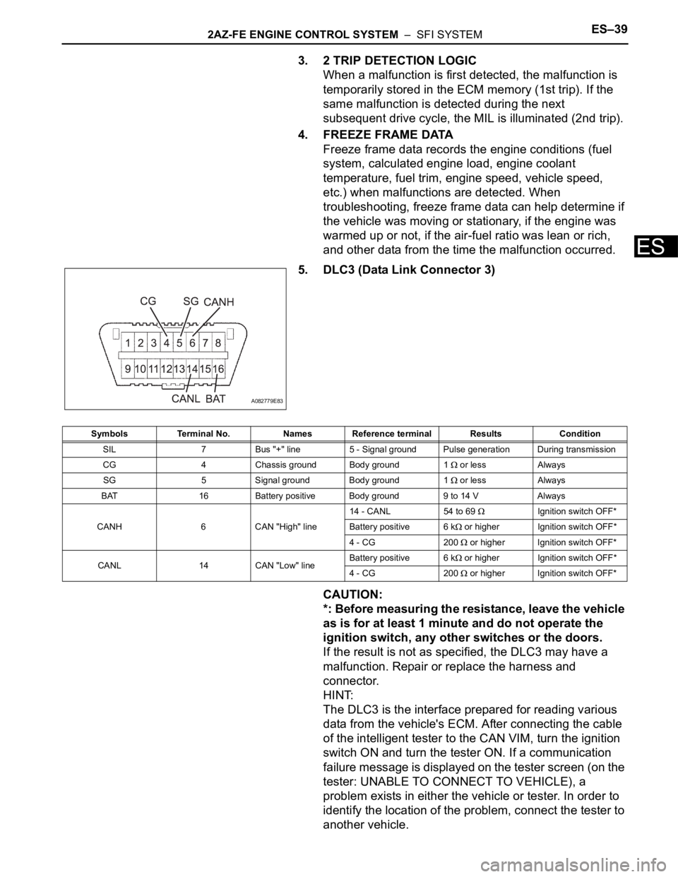
5. DLC3 (Data Link Connector 3)
CAUTION:
*: Before measuring the resistance, leave the vehicle
as is for at least 1 minute and do not operate the
ignition switch, any other switches or the doors.
If the result is not as specified, the DLC3 may have a
malfunction. Repair or replace the harness and
connector.
HINT:
The DLC3 is the interface prepared for reading various
data from the vehicle's ECM. After connecting the cable
of the intelligent tester to the CAN VIM, turn the ignition
switch ON and turn the tester ON. If a communication
failure message is displayed on the tester screen (on the
tester: UNABLE TO CONNECT TO VEHICLE), a
problem exists in either the vehicle or tester. In order to
identify the location of the problem, connect the tester to
another vehicle.
A082779E83
Symbols Terminal No. Names Reference terminal Results Condition
SIL 7 Bus "+" line 5 - Signal ground Pulse generation During transmission
CG 4 Chassis ground Body ground 1
or less Always
SG 5 Signal ground Body ground 1
or less Always
BAT 16 Battery positive Body ground 9 to 14 V Always
CANH 6 CAN "High" line14 - CANL 54 to 69
Ignition switch OFF*
Battery positive 6 k
or higher Ignition switch OFF*
4 - CG 200
or higher Ignition switch OFF*
CANL 14 CAN "Low" lineBattery positive 6 k
or higher Ignition switch OFF*
4 - CG 200
or higher Ignition switch OFF*
Page 495 of 2000
2AZ-FE ENGINE CONTROL SYSTEM – SFI SYSTEMES–41
ES
DTC CHECK / CLEAR
NOTICE:
When the diagnosis system is changed from normal
mode to check mode or vice versa, all DTCs and freeze
frame data recorded in normal mode are erased. Before
changing modes, always check and make a note of any
DTCs and freeze frame data.
HINT:
• DTCs which are stored in the ECM can be displayed on
the intelligent tester. The intelligent tester can display
current and pending DTCs.
• Some DTCs are not set if the ECM does not detect the
same malfunction again during a second consecutive
driving cycle. However, such malfunctions, detected on
only one occasion, are stored as pending DTCs.
1. CHECK DTC (Using intelligent tester)
(a) Connect the intelligent tester to the DLC3.
(b) Turn the ignition switch ON.
(c) Turn the tester ON.
(d) Select the following menu items: DIAGNOSIS /
ENHANCED OBD II / DTC INFO / CURRENT
CODES or PENDING CODES.
(e) Check the DTC(s) and freeze frame data, and then
write them down.
(f) Check the details of the DTC(s) (see page ES-51).
2. CLEAR DTC (Using intelligent tester)
(a) Connect the intelligent tester to the DLC3.
(b) Turn the ignition switch ON.
(c) Turn the tester ON.
(d) Select the following menu items: DIAGNOSIS /
ENHANCED OBD II / DTC INFO / CLEAR CODES.
(e) Press the YES button.
3. CLEAR DTC (Without using intelligent tester)
(a) Perform either of the following operations.
(1) Disconnect the cable from the negative (-)
battery terminal for more than 1 minute.
(2) Remove the EFI and ETCS fuses from the
engine room relay block (located inside the
engine compartment) for more than 1 minute.
Page 496 of 2000

ES–422AZ-FE ENGINE CONTROL SYSTEM – SFI SYSTEM
ES
FREEZE FRAME DATA
1. DESCRIPTION
Freeze frame data records the engine conditions (fuel
system, calculated load, engine coolant temperature,
fuel trim, engine speed, vehicle speed, etc.) when a
malfunction is detected. When troubleshooting, it can
help determine if the vehicle was running or stopped, the
engine was warmed up or not, the air-fuel ratio was Lean
or Rich, and other data from the time the malfunction
occurred.
HINT:
If it is impossible to duplicate the problem even though a
DTC is detected, confirm the freeze frame data.
The ECM records engine conditions in the form of freeze
frame data every 0.5 seconds. Using the intelligent
tester, 5 separate sets of freeze frame data can be
checked.
– 3 data sets before the DTC was set.
– 1 data set when the DTC was set.
– 1 data set after the DTC was set.
These data sets can be used to simulate the condition
of the vehicle around the time of the occurrence of the
malfunction. The data may assist in identifying the
cause of the malfunction, and in judging whether it
was temporary or not.
2. LIST OF FREEZE FRAME DATA
A103809E11
LABEL
(Intelligent Tester Display)Measurement Item Diagnostic Note
INJECTOR Injection period of No. 1 cylinder -
IGN ADVANCE Ignition advance -
CALC LOAD Calculated load Calculated load by ECM
VEHICLE LOAD Vehicle load -
MAF Mass air flow volumeIf approximately 0.0 g/sec.:
• Mass air flow meter power source circuit
open or short
• VG circuit open or short
If 160.0 g/sec. or more:
• E2G circuit open
ENGINE SPD Engine speed -
VEHICLE SPD Vehicle speed Speed indicated on speedometer
COOLANT TEMP Engine coolant temperatureIf -40
C (-40F), sensor circuit open
If 140
C (284F) or more, sensor circuit
shorted
INTAKE AIR Intake air temperature If -40
C (-40F), sensor circuit open
If 140
C (284F) or more, sensor circuit
shorted
AIR-FUEL RATIO Ratio compared to stoichiometric level -
PURGE DENSITY Learning value of purge density -
EVAP PURGE FLOWRatio of evaporative purge flow to intake air
volume-
EVAP PURGE VSV EVAP purge VSV duty ratio -
KNOCK CRRT VAL Correction learning value of knocking -