Page 1062 of 1556
Downloaded from www.Manualslib.com manuals search engine 8B-23 Air Bag System:
Serial Data Link Circuit CheckS6RW0D8204051
Wiring Diagram
1
2
3
3
18
12V
RED 7
14 9
10
“L313”
“G273”
YEL/BLKL04-2
L04-27 “L04”
PPL/WHT
“G04”L04-3212V
8
GRN
15
+BB
56WHTWHT
4
BLUBLU
BLK
16
11
12
“G241”
13
BLK
L04-28
RED/BLK
WHT/REDYEL/BLK
BLK“G271”
“G272”
WHT/RED
BLK/
ORNBLK
B
C
A A
A
17
[A]
A
[B]
12V
PPL/WHTYEL14
17A
A
YELL04-37
12V
I6RW0C820006-01
[A]: Junction block with BCM model 4. Individual circuit fuse box No.1 12. “METER” fuse
[B]: Junction block without BCM model (That
is, TAIWAN spec model)5. “IGN” fuse 13. “A/B” fuse
A: Serial data circuit 6. Ignition switch 14. BCM
B: DLC power supply circuit 7. Combination meter 15. Data link connector (DLC)
C: DLC ground circuit 8. “AIR BAG” warning light 16. Ground for air system
1. Battery 9. Light driver 17. To HVAC control module (auto A/C model)
2. Main fuse 10. Junction block assembly 18. SDM
3. Fuse 11. “DOME” fuse
Page 1070 of 1556
Downloaded from www.Manualslib.com manuals search engine 8B-31 Air Bag System:
NOTE
Upon completion of inspection and repair work, perform the following items.
• Reconnect all air bag system components and ensure all components are properly mounted.
• Repeat “Air Bag Diagnostic System Check” to confirm that the trouble has been corrected.
• Clear DTC B1157 (air bag deployed) of BCM referring to “DTC Clearance in Section 10B”, if any.
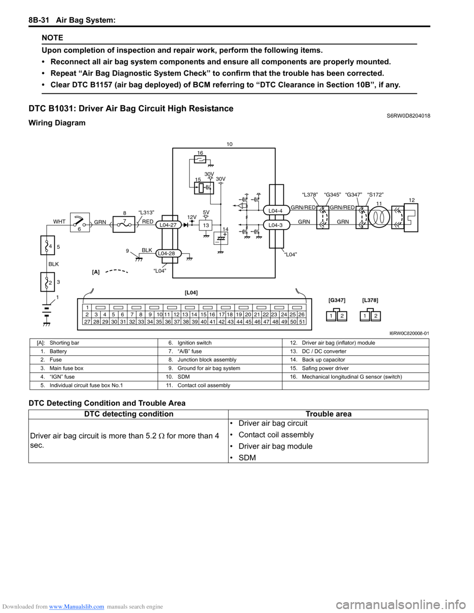
DTC B1031: Driver Air Bag Circuit High Resistance S6RW0D8204018
Wiring Diagram
DTC Detecting Condition and Trouble Area
“L04”“L04”[A]
BLK
L04-28
6 8
7
RED
GRN“L313”L04-27
910
L04-3 L04-4
1
2 3 4 5 6 7 8 9 10 11 12 13 14 15 16 17 18 19 20 21 22 23 24 25 26
27 28 29 30 31 32 33 34 35 36 37 38 39 40 41 42 43 44 45 46 47 48 49 50 51
12 [L04]
[G347]12 [L378]
15
13
16
12V5V30V 30V
141112
GRN/RED GRN/RED
GRN GRN
“G347” “S172” “L378” “G345”
1
2 BLKWHT3
4
5
I6RW0C820008-01
[A]: Shorting bar 6. Ignition switch 12. Driver air bag (inflator) module
1. Battery 7. “A/B” fuse 13. DC / DC converter
2. Fuse 8. Junction block assembly 14. Back up capacitor
3. Main fuse box 9. Ground for air bag system 15. Safing power driver
4. “IGN” fuse 10. SDM 16. Mechanical longitudinal G sensor (switch)
5. Individual circuit fuse box No.1 11. Contact coil assembly
DTC detecting condition Trouble area
Driver air bag circuit is more than 5.2 Ω for more than 4
sec.• Driver air bag circuit
• Contact coil assembly
• Driver air bag module
•SDM
Page 1079 of 1556
Downloaded from www.Manualslib.com manuals search engine Air Bag System: 8B-40
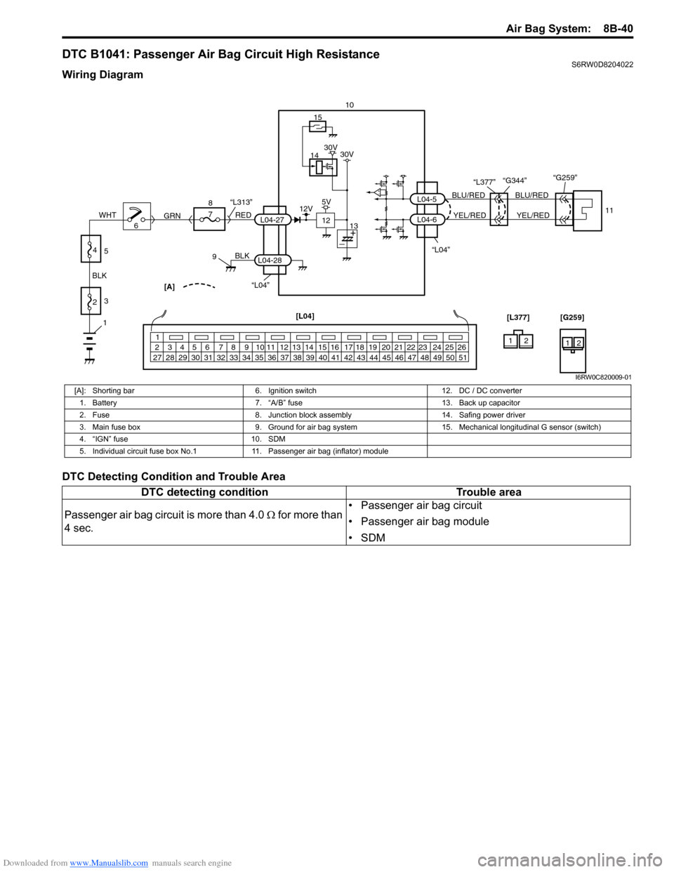
DTC B1041: Passenger Air Bag Circuit High ResistanceS6RW0D8204022
Wiring Diagram
DTC Detecting Condition and Trouble Area
“L04”[A]
BLK
L04-28
6 8
7
RED
GRN“L313”L04-27
910
1
2 3 4 5 6 7 8 9 10 11 12 13 14 15 16 17 18 19 20 21 22 23 24 25 26
27 28 29 30 31 32 33 34 35 36 37 38 39 40 41 42 43 44 45 46 47 48 49 50 51
[L04]
14
12
15
12V5V30V 30V
13
11
BLU/RED
YEL/RED
L04-6 L04-5
“L377”
“L04”“G344”“G259”
BLU/RED
YEL/RED
1
2 BLKWHT3
4
5
12 [L377] [G259]
12
I6RW0C820009-01
[A]: Shorting bar 6. Ignition switch 12. DC / DC converter
1. Battery 7. “A/B” fuse 13. Back up capacitor
2. Fuse 8. Junction block assembly 14. Safing power driver
3. Main fuse box 9. Ground for air bag system 15.Mechanical longitudinal G sensor (switch)
4. “IGN” fuse 10. SDM
5. Individual circuit fuse box No.1 11. Passenger air bag (inflator) module
DTC detecting condition Trouble area
Passenger air bag circuit is more than 4.0 Ω for more than
4 sec.• Passenger air bag circuit
• Passenger air bag module
•SDM
Page 1087 of 1556
Downloaded from www.Manualslib.com manuals search engine Air Bag System: 8B-48
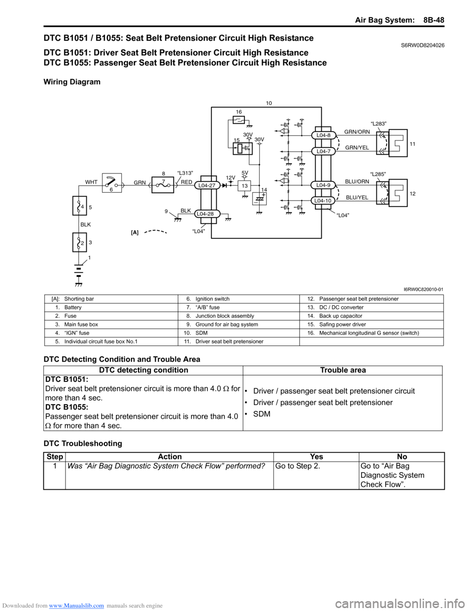
DTC B1051 / B1055: Seat Belt Pretensioner Circuit High ResistanceS6RW0D8204026
DTC B1051: Driver Seat Belt Pretensioner Circuit High Resistance
DTC B1055: Passenger Seat Belt Pretensioner Circuit High Resistance
Wiring Diagram
DTC Detecting Condition and Trouble Area
DTC Troubleshooting
“L04”[A]
BLK
L04-28
6 8
7
RED
GRN“L313”L04-27
910
15
13
16
12V5V30V 30V
14
1
2 BLKWHT3
4
5
“L04”
GRN/ORN
GRN/YEL
BLU/ORN
BLU/YEL
L04-9
L04-7
L04-8
11
12 “L283”
L04-10
“L285”
I6RW0C820010-01
[A]: Shorting bar 6. Ignition switch 12. Passenger seat belt pretensioner
1. Battery 7. “A/B” fuse 13. DC / DC converter
2. Fuse 8. Junction block assembly 14. Back up capacitor
3. Main fuse box 9. Ground for air bag system 15. Safing power driver
4. “IGN” fuse 10. SDM 16. Mechanical longitudinal G sensor (switch)
5. Individual circuit fuse box No.1 11. Driver seat belt pretensioner
DTC detecting condition Trouble area
DTC B1051:
Driver seat belt pretensioner circuit is more than 4.0 Ω for
more than 4 sec.
DTC B1055:
Passenger seat belt pretensioner circuit is more than 4.0
Ω for more than 4 sec.• Driver / passenger seat belt pretensioner circuit
• Driver / passenger seat belt pretensioner
•SDM
Step Action Yes No
1Was “Air Bag Diagnostic System Check Flow” performed?Go to Step 2. Go to “Air Bag
Diagnostic System
Check Flow”.
Page 1094 of 1556
Downloaded from www.Manualslib.com manuals search engine 8B-55 Air Bag System:
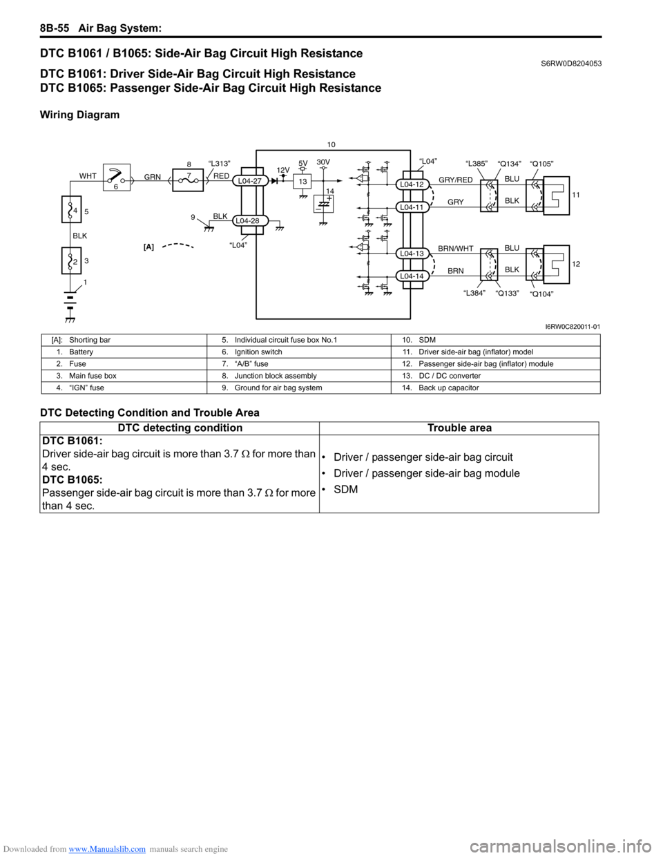
DTC B1061 / B1065: Side-Air Bag Circuit High ResistanceS6RW0D8204053
DTC B1061: Driver Side-Air Bag Circuit High Resistance
DTC B1065: Passenger Side-Air Bag Circuit High Resistance
Wiring Diagram
DTC Detecting Condition and Trouble Area
“L04”[A]
BLK
L04-28
6 8
7
RED
GRN“L313”L04-27
910
13
12V5V30V
14
1
2 BLKWHT3
4
5
“L04”
GRY/RED
GRYBLU
BLK
BLU
BLK L04-12
L04-11
11 “Q134” “Q105” “L385”
BRN/WHT
BRN L04-13
L04-14
12
“Q104” “Q133” “L384”
I6RW0C820011-01
[A]: Shorting bar 5. Individual circuit fuse box No.1 10. SDM
1. Battery 6. Ignition switch 11. Driver side-air bag (inflator) model
2. Fuse 7. “A/B” fuse 12. Passenger side-air bag (inflator) module
3. Main fuse box 8. Junction block assembly 13. DC / DC converter
4. “IGN” fuse 9. Ground for air bag system 14. Back up capacitor
DTC detecting condition Trouble area
DTC B1061:
Driver side-air bag circuit is more than 3.7 Ω for more than
4 sec.
DTC B1065:
Passenger side-air bag circuit is more than 3.7 Ω for more
than 4 sec.• Driver / passenger side-air bag circuit
• Driver / passenger side-air bag module
•SDM
Page 1106 of 1556
Downloaded from www.Manualslib.com manuals search engine 8B-67 Air Bag System:
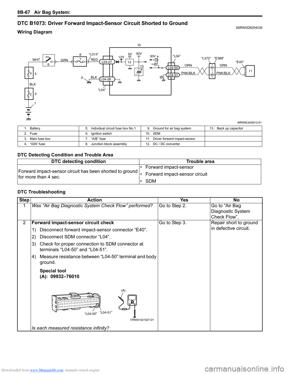
DTC B1073: Driver Forward Impact-Sensor Circuit Shorted to GroundS6RW0D8204036
Wiring Diagram
DTC Detecting Condition and Trouble Area
DTC Troubleshooting
10
“L04”
“L372” “E388”
“E40”
ORN
PNK/BLKORN
PNK/BLKL04-50
L04-5111
30V
“L04”
BLK
L04-28
6 8
7
RED
GRN“L313”L04-27
9
1
2 BLKWHT3
4
5
12
12V5V30V
13
I6RW0C820012-01
1. Battery 5. Individual circuit fuse box No.1 9. Ground for air bag system 13. Back up capacitor
2. Fuse 6. Ignition switch 10. SDM
3. Main fuse box 7. “A/B” fuse 11. Driver forward impact-sensor
4. “IGN” fuse 8. Junction block assembly 12. DC / DC converter
DTC detecting condition Trouble area
Forward impact-sensor circuit has been shorted to ground
for more than 4 sec.• Forward impact-sensor
• Forward impact-sensor circuit
•SDM
Step Action Yes No
1Was “Air Bag Diagnostic System Check Flow” performed?Go to Step 2. Go to “Air Bag
Diagnostic System
Check Flow”.
2Forward impact-sensor circuit check
1) Disconnect forward impact-sensor connector “E40”.
2) Disconnect SDM connector “L04”.
3) Check for proper connection to SDM connector at
terminals “L04-50” and “L04-51”.
4) Measure resistance between “L04-50” terminal and body
ground.
Special tool
(A): 09932–76010
Is each measured resistance infinity?Go to Step 3. Repair short to ground
in defective circuit.
“L04-50”“L04-51”
(A)
I7RW01821027-01
Page 1110 of 1556
Downloaded from www.Manualslib.com manuals search engine 8B-71 Air Bag System:
DTC Troubleshooting
NOTE
Upon completion of inspection and repair work, perform the following items.
• Reconnect all air bag system components and ensure all components are properly mounted.
• Clear DTCs referring to “DTC Clearance”, if any.
• Repeat “Air Bag Diagnostic System Check” to confirm that the trouble has been corrected.
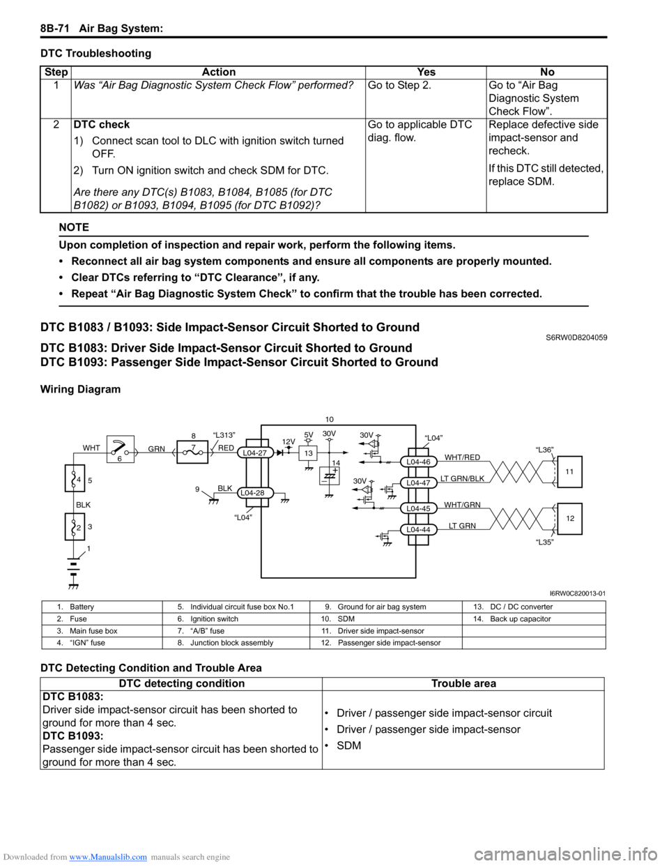
DTC B1083 / B1093: Side Impact-Sensor Circuit Shorted to GroundS6RW0D8204059
DTC B1083: Driver Side Impact-Sensor Circuit Shorted to Ground
DTC B1093: Passenger Side Impact-Sensor Circuit Shorted to Ground
Wiring Diagram
DTC Detecting Condition and Trouble AreaStep Action Yes No
1Was “Air Bag Diagnostic System Check Flow” performed?Go to Step 2. Go to “Air Bag
Diagnostic System
Check Flow”.
2DTC check
1) Connect scan tool to DLC with ignition switch turned
OFF.
2) Turn ON ignition switch and check SDM for DTC.
Are there any DTC(s) B1083, B1084, B1085 (for DTC
B1082) or B1093, B1094, B1095 (for DTC B1092)?Go to applicable DTC
diag. flow.Replace defective side
impact-sensor and
recheck.
If this DTC still detected,
replace SDM.
10
“L04”30V
30VL04-47 L04-46WHT/RED
LT GRN/BLK“L36”
11
L04-44 L04-45WHT/GRN
LT GRN
“L35”12
“L04”
BLK
L04-28
6 8
7
RED
GRN“L313”L04-27
9
1
2 BLKWHT3
4
5
13
12V5V30V
14
I6RW0C820013-01
1. Battery 5. Individual circuit fuse box No.1 9. Ground for air bag system 13. DC / DC converter
2. Fuse 6. Ignition switch 10. SDM 14. Back up capacitor
3. Main fuse box 7. “A/B” fuse 11. Driver side impact-sensor
4. “IGN” fuse 8. Junction block assembly 12. Passenger side impact-sensor
DTC detecting condition Trouble area
DTC B1083:
Driver side impact-sensor circuit has been shorted to
ground for more than 4 sec.
DTC B1093:
Passenger side impact-sensor circuit has been shorted to
ground for more than 4 sec.• Driver / passenger side impact-sensor circuit
• Driver / passenger side impact-sensor
•SDM
Page 1114 of 1556
Downloaded from www.Manualslib.com manuals search engine 8B-75 Air Bag System:
NOTE
Upon completion of inspection and repair work, perform the following items.
• Reconnect all air bag system components and ensure all components are properly mounted.
• Clear DTCs referring to “DTC Clearance”, if any.
• Repeat “Air Bag Diagnostic System Check” to confirm that the trouble has been corrected.
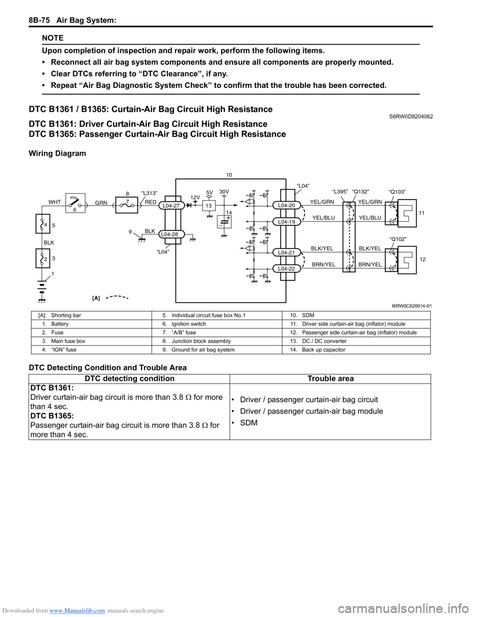
DTC B1361 / B1365: Curtain-Air Bag Circuit High ResistanceS6RW0D8204062
DTC B1361: Driver Curtain-Air Bag Circuit High Resistance
DTC B1365: Passenger Curtain-Air Bag Circuit High Resistance
Wiring Diagram
DTC Detecting Condition and Trouble Area
10
L04-20
L04-19
L04-21
L04-22
YEL/GRN
YEL/BLU
BLK/YEL
BRN/YELYEL/GRN
YEL/BLU
BLK/YEL
BRN/YEL “L395” “Q132”
11
12
“L04”
“Q102” “Q103”
“L04”
BLK
L04-28
6 8
7
RED
GRN“L313”L04-27
9
1
2 BLKWHT3
4
5
[A]
13
12V5V30V
14
I6RW0C820014-01
[A]: Shorting bar 5. Individual circuit fuse box No.1 10. SDM
1. Battery 6. Ignition switch 11. Driver side curtain-air bag (inflator) module
2. Fuse 7. “A/B” fuse 12. Passenger side curtain-air bag (inflator) module
3. Main fuse box 8. Junction block assembly 13. DC / DC converter
4. “IGN” fuse 9. Ground for air bag system 14. Back up capacitor
DTC detecting condition Trouble area
DTC B1361:
Driver curtain-air bag circuit is more than 3.8 Ω for more
than 4 sec.
DTC B1365:
Passenger curtain-air bag circuit is more than 3.8 Ω for
more than 4 sec.• Driver / passenger curtain-air bag circuit
• Driver / passenger curtain-air bag module
•SDM