2006 SUZUKI SX4 Shift switch
[x] Cancel search: Shift switchPage 828 of 1556

Downloaded from www.Manualslib.com manuals search engine 5B-16 Manual Transmission/Transaxle:
Manual Transaxle Assembly ComponentsS6RW0D5206014
I5RW0A520018-03
1. Transaxle right case 22. Shift fork bolt
: Apply thread lock 99000-32110 to all around thread part of bolt.
2. Transaxle left case
: Apply sealant 99000-31260 to mating surface of left case and right
case.23. 5th gear shift fork
3. Gear shift and select shaft assembly
: Apply sealant 99000-31260 to mating surface of guide case and left
case.24. Needle bearing
4. Transaxle left case plate 25. Input shaft 5th gear
5. Transaxle side cover
: Apply sealant 99000-31260 to mating surface of side cover and left
case.26. Reverse gear shift lever
6. Back up light switch 27. Reverse gear shift lever bolt
: Apply thread lock 99000-32110 to all around thread part of bolt.
7. O-ring28. Reverse gear shaft
8. Differential assembly 29. Washer
9. Oil level / filler plug
: Apply sealant 99000-31260 to all around thread part of plug.30. Reverse idler gear
Page 850 of 1556

Downloaded from www.Manualslib.com manuals search engine 5B-38 Manual Transmission/Transaxle:
4) Press-fit right bearing (1) by using special tools and
hydraulic press.
Special tool
(A): 09925–15410
(B): 09924–07720
(C): 09913–852305) Hold differential assembly with soft jawed vise (3),
install final gear (2) and then tighten new final gear
bolts (1).
CAUTION!
Use of any other bolts than specified ones is
prohibited. Otherwise, bolts may loosen.
Tightening torque
Final gear bolt (a): 90 N·m (9.0 kgf-m, 65.0 lb-ft)
Specifications
Tightening Torque SpecificationsS6RW0D5207001
NOTE
The specified tightening torque is also described in the following.
“Gear Shift Control Lever and Cable Components”
“Manual Transaxle Unit Components”
“Gear Shift and Select Shaft Assembly Components”
“Manual Transaxle Assembly Components”
“Gear Shift Shaft Components”
“Differential Components”
Reference:
For the tightening torque of fastener not specified in this section, refer to “Fasteners Information in Section 0A”.
2. Differential case
3. Differential side left bearing
I5RW0A520048-01I5RW0A520049-01
Fastening partTightening torque
Note
N⋅mkgf-mlb-ft
Transaxle oil level / filler plug 21 2.1 15.5�) / �)
Transaxle oil drain plug 21 2.1 15.5�)
Back up light switch 23 2.3 17.0�)
Guide case bolt No.1 23 2.3 17.0�)
Guide case bolt No.2 23 2.3 17.0�)
Gear shift interlock bolt 23 2.3 17.0�)
5th to reverse interlock guide bolt 23 2.3 17.0�)
Countershaft nut 100 10.0 75.0�)
Shift fork shaft bolt 10 1.0 7.5�)
Side cover bolt 10 1.0 7.5�)
Reverse gear shift lever bolt 23 2.3 17.0�)
Transaxle case bolt 23 2.3 17.0�)
Reverse shaft bolt 23 2.3 17.0�)
Gear shift locating bolt 13 1.3 9.5�)
Left case plate bolt 23 2.3 17.0�)
Oil gutter bolt 10 1.0 7.5�)
Final gear bolt 90 9.0 65.0�)
Page 1163 of 1556
Downloaded from www.Manualslib.com manuals search engine Table of Contents 9-iii
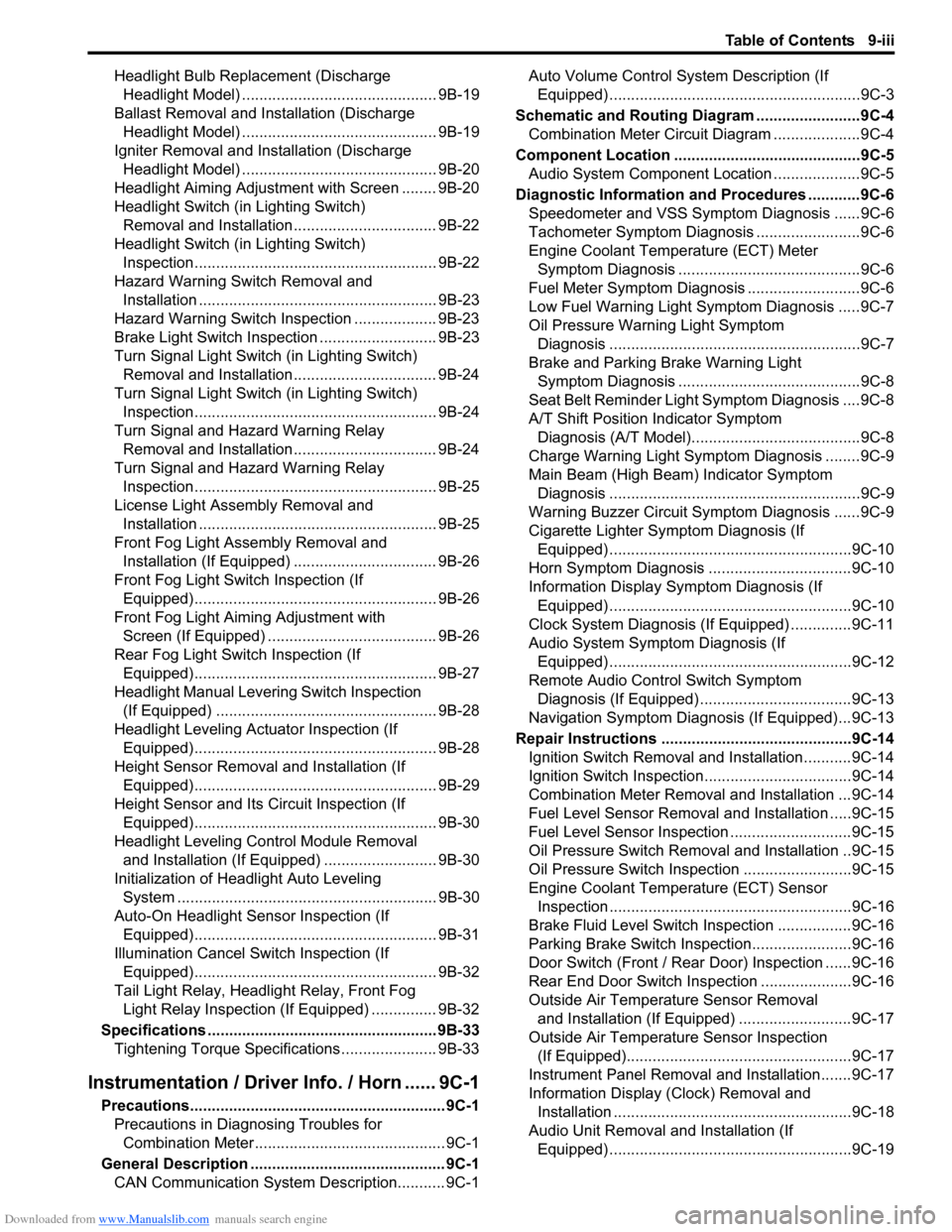
Headlight Bulb Replacement (Discharge
Headlight Model) ............................................. 9B-19
Ballast Removal and Installation (Discharge
Headlight Model) ............................................. 9B-19
Igniter Removal and Installation (Discharge
Headlight Model) ............................................. 9B-20
Headlight Aiming Adjustment with Screen ........ 9B-20
Headlight Switch (in Lighting Switch)
Removal and Installation................................. 9B-22
Headlight Switch (in Lighting Switch)
Inspection........................................................ 9B-22
Hazard Warning Switch Removal and
Installation ....................................................... 9B-23
Hazard Warning Switch Inspection ................... 9B-23
Brake Light Switch Inspection ........................... 9B-23
Turn Signal Light Switch (in Lighting Switch)
Removal and Installation................................. 9B-24
Turn Signal Light Switch (in Lighting Switch)
Inspection........................................................ 9B-24
Turn Signal and Hazard Warning Relay
Removal and Installation................................. 9B-24
Turn Signal and Hazard Warning Relay
Inspection........................................................ 9B-25
License Light Assembly Removal and
Installation ....................................................... 9B-25
Front Fog Light Assembly Removal and
Installation (If Equipped) ................................. 9B-26
Front Fog Light Switch Inspection (If
Equipped)........................................................ 9B-26
Front Fog Light Aiming Adjustment with
Screen (If Equipped) ....................................... 9B-26
Rear Fog Light Switch Inspection (If
Equipped)........................................................ 9B-27
Headlight Manual Levering Switch Inspection
(If Equipped) ................................................... 9B-28
Headlight Leveling Actuator Inspection (If
Equipped)........................................................ 9B-28
Height Sensor Removal and Installation (If
Equipped)........................................................ 9B-29
Height Sensor and Its Circuit Inspection (If
Equipped)........................................................ 9B-30
Headlight Leveling Control Module Removal
and Installation (If Equipped) .......................... 9B-30
Initialization of Headlight Auto Leveling
System ............................................................ 9B-30
Auto-On Headlight Sensor Inspection (If
Equipped)........................................................ 9B-31
Illumination Cancel Switch Inspection (If
Equipped)........................................................ 9B-32
Tail Light Relay, Headlight Relay, Front Fog
Light Relay Inspection (If Equipped) ............... 9B-32
Specifications..................................................... 9B-33
Tightening Torque Specifications ...................... 9B-33
Instrumentation / Driver Info. / Horn ...... 9C-1
Precautions........................................................... 9C-1
Precautions in Diagnosing Troubles for
Combination Meter............................................ 9C-1
General Description ............................................. 9C-1
CAN Communication System Description........... 9C-1Auto Volume Control System Description (If
Equipped) ..........................................................9C-3
Schematic and Routing Diagram ........................9C-4
Combination Meter Circuit Diagram ....................9C-4
Component Location ...........................................9C-5
Audio System Component Location ....................9C-5
Diagnostic Information and Procedures ............9C-6
Speedometer and VSS Symptom Diagnosis ......9C-6
Tachometer Symptom Diagnosis ........................9C-6
Engine Coolant Temperature (ECT) Meter
Symptom Diagnosis ..........................................9C-6
Fuel Meter Symptom Diagnosis ..........................9C-6
Low Fuel Warning Light Symptom Diagnosis .....9C-7
Oil Pressure Warning Light Symptom
Diagnosis ..........................................................9C-7
Brake and Parking Brake Warning Light
Symptom Diagnosis ..........................................9C-8
Seat Belt Reminder Light Symptom Diagnosis ....9C-8
A/T Shift Position Indicator Symptom
Diagnosis (A/T Model).......................................9C-8
Charge Warning Light Symptom Diagnosis ........9C-9
Main Beam (High Beam) Indicator Symptom
Diagnosis ..........................................................9C-9
Warning Buzzer Circuit Symptom Diagnosis ......9C-9
Cigarette Lighter Symptom Diagnosis (If
Equipped) ........................................................9C-10
Horn Symptom Diagnosis .................................9C-10
Information Display Symptom Diagnosis (If
Equipped) ........................................................9C-10
Clock System Diagnosis (If Equipped) ..............9C-11
Audio System Symptom Diagnosis (If
Equipped) ........................................................9C-12
Remote Audio Control Switch Symptom
Diagnosis (If Equipped) ...................................9C-13
Navigation Symptom Diagnosis (If Equipped)...9C-13
Repair Instructions ............................................9C-14
Ignition Switch Removal and Installation...........9C-14
Ignition Switch Inspection..................................9C-14
Combination Meter Removal and Installation ...9C-14
Fuel Level Sensor Removal and Installation .....9C-15
Fuel Level Sensor Inspection ............................9C-15
Oil Pressure Switch Removal and Installation ..9C-15
Oil Pressure Switch Inspection .........................9C-15
Engine Coolant Temperature (ECT) Sensor
Inspection ........................................................9C-16
Brake Fluid Level Switch Inspection .................9C-16
Parking Brake Switch Inspection.......................9C-16
Door Switch (Front / Rear Door) Inspection ......9C-16
Rear End Door Switch Inspection .....................9C-16
Outside Air Temperature Sensor Removal
and Installation (If Equipped) ..........................9C-17
Outside Air Temperature Sensor Inspection
(If Equipped)....................................................9C-17
Instrument Panel Removal and Installation.......9C-17
Information Display (Clock) Removal and
Installation .......................................................9C-18
Audio Unit Removal and Installation (If
Equipped) ........................................................9C-19
Page 1178 of 1556
Downloaded from www.Manualslib.com manuals search engine 9A-11 Wiring Systems:
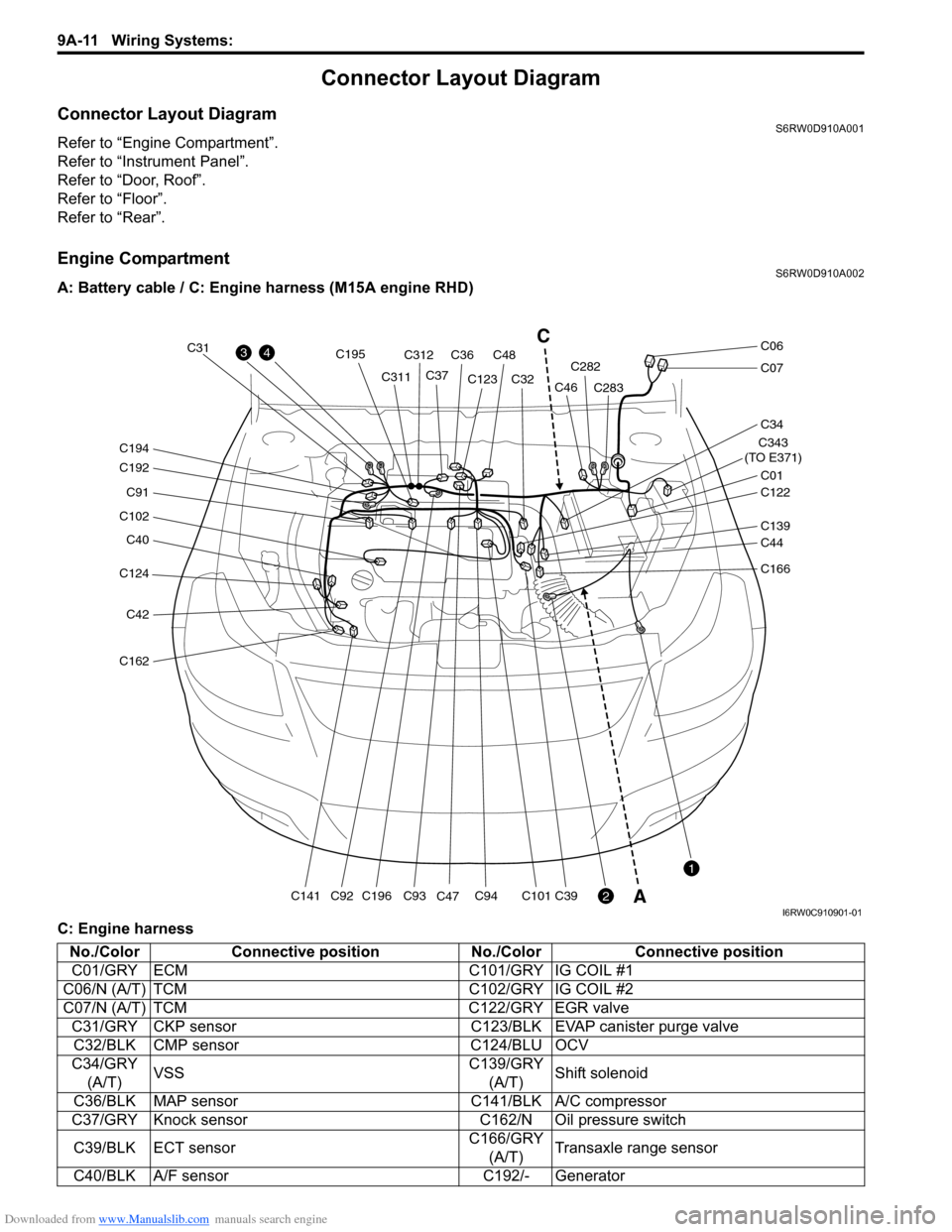
Connector Layout Diagram
Connector Layout DiagramS6RW0D910A001
Refer to “Engine Compartment”.
Refer to “Instrument Panel”.
Refer to “Door, Roof”.
Refer to “Floor”.
Refer to “Rear”.
Engine CompartmentS6RW0D910A002
A: Battery cable / C: Engine harness (M15A engine RHD)
C: Engine harness
C124
C40
C102
C91
C192
C194
C42
C162
C141C196
C195
C93C94C101C39C92
C31
C311C312
C36C48
C37C123
C47C32C282
C283
C343
(TO E371)
C01
C34
C07
C06
C122
C46
C139
C44
C166
43
2
1
C
A
I6RW0C910901-01
No./Color Connective position No./Color Connective position
C01/GRY ECM C101/GRY IG COIL #1
C06/N (A/T) TCM C102/GRY IG COIL #2
C07/N (A/T) TCM C122/GRY EGR valve
C31/GRY CKP sensor C123/BLK EVAP canister purge valve
C32/BLK CMP sensor C124/BLU OCV
C34/GRY
(A/T)VSSC139/GRY
(A/T)Shift solenoid
C36/BLK MAP sensor C141/BLK A/C compressor
C37/GRY Knock sensor C162/N Oil pressure switch
C39/BLK ECT sensorC166/GRY
(A/T)Transaxle range sensor
C40/BLK A/F sensor C192/- Generator
Page 1179 of 1556
Downloaded from www.Manualslib.com manuals search engine Wiring Systems: 9A-12
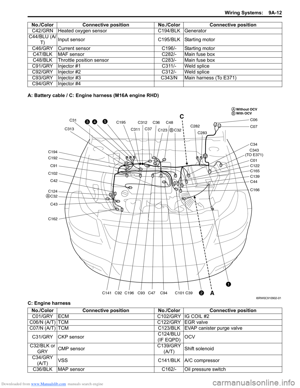
A: Battery cable / C: Engine harness (M16A engine RHD)
C: Engine harnessC42/GRN Heated oxygen sensor C194/BLK Generator
C44/BLU (A/
T)Input sensor C195/BLK Starting motor
C46/GRY Current sensor C196/- Starting motor
C47/BLK MAF sensor C282/- Main fuse box
C48/BLK Throttle position sensor C283/- Main fuse box
C91/GRY Injector #1 C311/- Weld splice
C92/GRY Injector #2 C312/- Weld splice
C93/GRY Injector #3 C343/N Main harness (To E371)
C94/GRY Injector #4 No./Color Connective position No./Color Connective position
C124
C32
C42
C102
C91
C192
C194
C43
C162
C141C196
C195
C93C94C101C39C92
C31
C311C313C312
C36C48
C37C123
C47C32C282
C283
C343
(TO E371)
C01
C34
C07
C06
C122
C165
C139
C44
C166
43
2
1
5C
A
Without OCV
With OCV A
A
B
B
I6RW0C910902-01
No./Color Connective position No./Color Connective position
C01/GRY ECM C102/GRY IG COIL #2
C06/N (A/T) TCM C122/GRY EGR valve
C07/N (A/T) TCM C123/BLK EVAP canister purge valve
C31/GRY CKP sensorC124/BLU
(IF EQPD)OCV
C32/BLK or
GRYCMP sensorC139/GRY
(A/T)Shift solenoid
C34/GRY
(A/T)VSS C141/BLK A/C compressor
C36/BLK MAP sensor C162/- Oil pressure switch
Page 1181 of 1556
Downloaded from www.Manualslib.com manuals search engine Wiring Systems: 9A-14
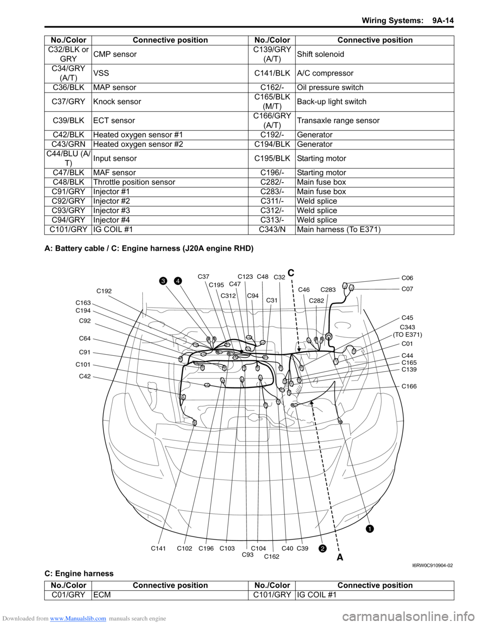
A: Battery cable / C: Engine harness (J20A engine RHD)
C: Engine harnessC32/BLK or
GRYCMP sensorC139/GRY
(A/T)Shift solenoid
C34/GRY
(A/T)VSS C141/BLK A/C compressor
C36/BLK MAP sensor C162/- Oil pressure switch
C37/GRY Knock sensorC165/BLK
(M/T)Back-up light switch
C39/BLK ECT sensorC166/GRY
(A/T)Transaxle range sensor
C42/BLK Heated oxygen sensor #1 C192/- Generator
C43/GRN Heated oxygen sensor #2 C194/BLK Generator
C44/BLU (A/
T)Input sensor C195/BLK Starting motor
C47/BLK MAF sensor C196/- Starting motor
C48/BLK Throttle position sensor C282/- Main fuse box
C91/GRY Injector #1 C283/- Main fuse box
C92/GRY Injector #2 C311/- Weld splice
C93/GRY Injector #3 C312/- Weld splice
C94/GRY Injector #4 C313/- Weld splice
C101/GRY IG COIL #1 C343/N Main harness (To E371)No./Color Connective position No./Color Connective position
C42
C101
C91
C64 C92
C194 C163
C141C102C196 C192
C195
C312
C93C104C103
C94C31C32
C40
C162
C39
C123C48C37
C47
C282
C283C46
C343
(TO E371)
C01
C45
C07
C06
C139 C44
C165
C166
3
2
1
4
A
C
I6RW0C910904-02
No./Color Connective position No./Color Connective position
C01/GRY ECM C101/GRY IG COIL #1
Page 1182 of 1556
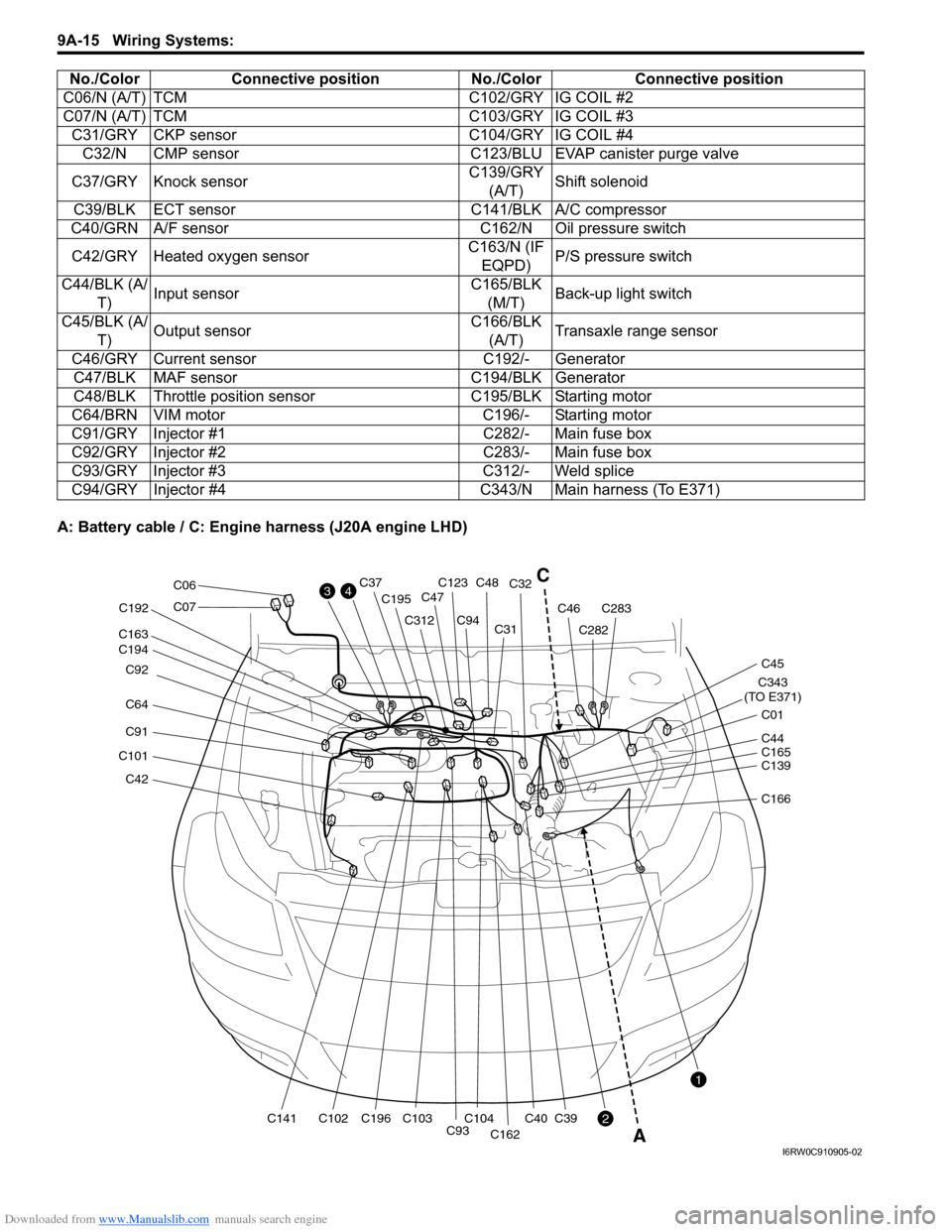
Downloaded from www.Manualslib.com manuals search engine 9A-15 Wiring Systems:
A: Battery cable / C: Engine harness (J20A engine LHD)C06/N (A/T) TCM C102/GRY IG COIL #2
C07/N (A/T) TCM C103/GRY IG COIL #3
C31/GRY CKP sensor C104/GRY IG COIL #4
C32/N CMP sensor C123/BLU EVAP canister purge valve
C37/GRY Knock sensorC139/GRY
(A/T)Shift solenoid
C39/BLK ECT sensor C141/BLK A/C compressor
C40/GRN A/F sensor C162/N Oil pressure switch
C42/GRY Heated oxygen sensorC163/N (IF
EQPD)P/S pressure switch
C44/BLK (A/
T)Input sensorC165/BLK
(M/T)Back-up light switch
C45/BLK (A/
T)Output sensorC166/BLK
(A/T)Transaxle range sensor
C46/GRY Current sensor C192/- Generator
C47/BLK MAF sensor C194/BLK Generator
C48/BLK Throttle position sensor C195/BLK Starting motor
C64/BRN VIM motor C196/- Starting motor
C91/GRY Injector #1 C282/- Main fuse box
C92/GRY Injector #2 C283/- Main fuse box
C93/GRY Injector #3 C312/- Weld splice
C94/GRY Injector #4 C343/N Main harness (To E371) No./Color Connective position No./Color Connective position
C42
C101
C91
C64 C92
C194 C163
C141C102C196 C192
C195
C312
C93C104C103
C94C31C32
C40
C162
C39
C123C48C37
C47
C282
C283C46
C343
(TO E371)
C01
C45
C07
C06
C139 C44
C165
C166
3
2
1
4C
A
I6RW0C910905-02
Page 1183 of 1556
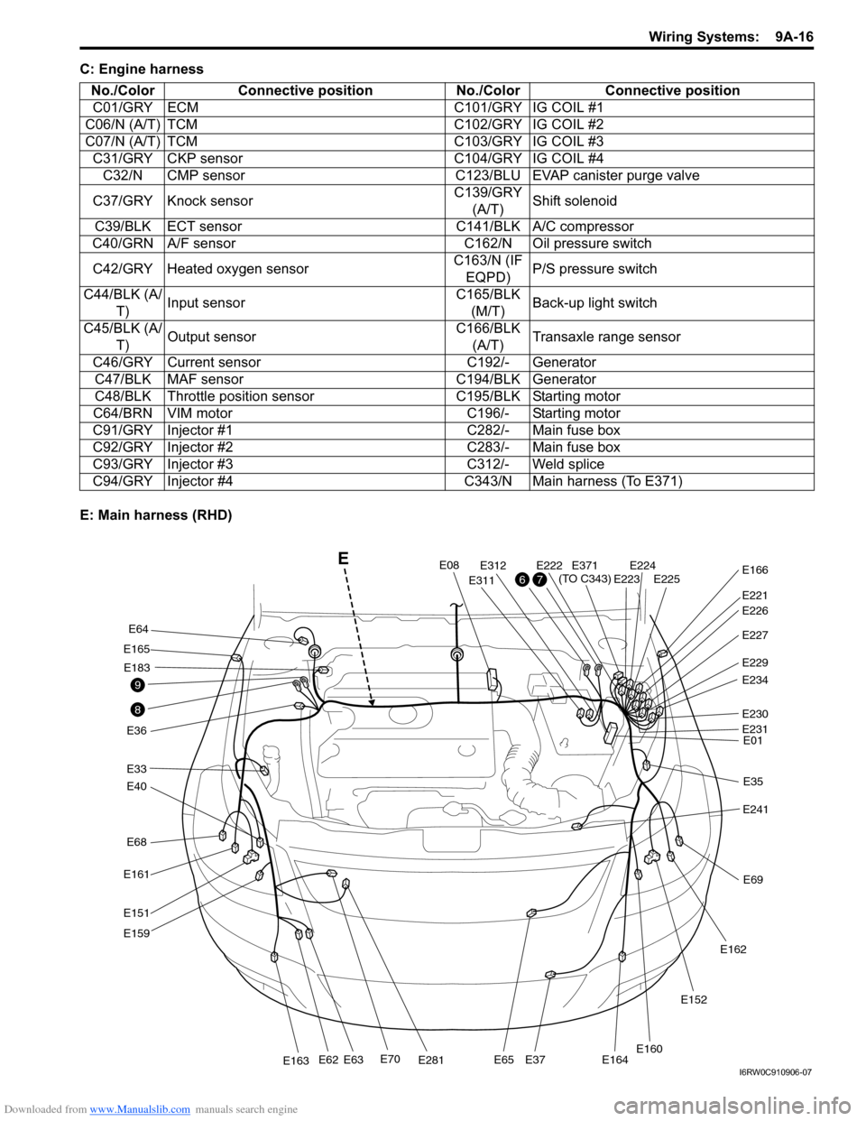
Downloaded from www.Manualslib.com manuals search engine Wiring Systems: 9A-16
C: Engine harness
E: Main harness (RHD)No./Color Connective position No./Color Connective position
C01/GRY ECM C101/GRY IG COIL #1
C06/N (A/T) TCM C102/GRY IG COIL #2
C07/N (A/T) TCM C103/GRY IG COIL #3
C31/GRY CKP sensor C104/GRY IG COIL #4
C32/N CMP sensor C123/BLU EVAP canister purge valve
C37/GRY Knock sensorC139/GRY
(A/T)Shift solenoid
C39/BLK ECT sensor C141/BLK A/C compressor
C40/GRN A/F sensor C162/N Oil pressure switch
C42/GRY Heated oxygen sensorC163/N (IF
EQPD)P/S pressure switch
C44/BLK (A/
T)Input sensorC165/BLK
(M/T)Back-up light switch
C45/BLK (A/
T)Output sensorC166/BLK
(A/T)Transaxle range sensor
C46/GRY Current sensor C192/- Generator
C47/BLK MAF sensor C194/BLK Generator
C48/BLK Throttle position sensor C195/BLK Starting motor
C64/BRN VIM motor C196/- Starting motor
C91/GRY Injector #1 C282/- Main fuse box
C92/GRY Injector #2 C283/- Main fuse box
C93/GRY Injector #3 C312/- Weld splice
C94/GRY Injector #4 C343/N Main harness (To E371)
E68
E40
E33
E165
E36
E161
E151
E159
E70E281E163E62E63E65E37E164
E64
E183
E08
E311
E312E222E224E225E223
E221
E371
(TO C343)E166
E227
E229
E234
E230
E01
E35
E241
E69
E162
E152
E160
E231
E226
8
9
76
E
I6RW0C910906-07