2006 SUZUKI SX4 Head unit
[x] Cancel search: Head unitPage 24 of 1556

Downloaded from www.Manualslib.com manuals search engine 0A-1 General Information:
General Information
General Information
General Description
AbbreviationsS6RW0D0101001
A:
ABDC: After Bottom Dead Center
ABS: Anti-lock Brake System
AC: Alternating Current
A/C: Air Conditioning
A-ELR: Automatic-Emergency Locking Retractor
A/F: Air Fuel Mixture Ratio
ALR: Automatic Locking Retractor
API: American Petroleum Institute
APP sensor: Accelerator Pedal Position Sensor
A/T: Automatic Transmission, Automatic Transaxle
AT D C : After Top Dead Center
ATF: Automatic Transmission Fluid, Automatic
Transaxle Fluid
B:
B+: Battery Positive Voltage
BBDC: Before Bottom Dead Center
BCM: Body Electrical Control Module
BTDC: Before Top Dead Center
C:
CAN: Controller Area Network
CKT: Circuit
CKP Sensor: Crankshaft Position Sensor
CMP Sensor: Camshaft Position Sensor
CO: Carbon Monoxide
CPP Switch: Clutch Pedal Position Switch (Clutch
Switch, Clutch Start Switch)
CPU: Central Processing Unit
CRS: Child Restraint System
D:
DC: Direct Current
DLC: Data Link Connector (Assembly Line Diag. Link,
ALDL, Serial Data Link, SDL)
DOHC: Double Over Head Camshaft
DOJ: Double Offset Joint
DRL: Daytime Running Light
DTC: Diagnostic Trouble Code (Diagnostic Code)
E:
EBCM: Electronic Brake Control Module, ABS Control
Module
EBD: Electronic Brake Force Distribution
ECM: Engine Control Module
ECT Sensor: Engine Coolant Temperature Sensor
(Water Temp. Sensor, WTS)
EFE Heater: Early Fuel Evaporation Heater (Positive
Temperature Coefficient, PTC Heater)
EGR: Exhaust Gas Recirculation
EGRT Sensor: EGR Temperature Sensor (Recirculated
Exhaust Gas Temp. Sensor, REGTS)
EPS: Electronic Power Steering
EVAP: Evaporative Emission
EVAP Canister: Evaporative Emission Canister
(Charcoal Canister)F:
4WD: 4 Wheel Drive
G:
GEN: Generator
GND: Ground
GPS: Global Positioning System
H:
HAVC: Heating, Ventilating and Air Conditioning
HC: Hydrocarbons
HO2S: Heated Oxygen Sensor
I:
IAC Valve: Idle Air Control Valve (Idle Speed Control
Solenoid Valve, ISC Solenoid Valve)
IAT Sensor: Intake Air Temperature Sensor (Air
temperature Sensor, ATS)
ICM: Immobilizer Control Module
IG: Ignition
ISC Actuator: Idle Speed Control Actuator
L:
LH: Left Hand
LHD: Left Hand Drive vehicle
LSPV: Load Sensing Proportioning Valve
M:
MAF Sensor: Mass Air Flow Sensor (Air Flow Sensor,
AFS, Air Flow Meter, AFM)
MAP Sensor: Manifold Absolute Pressure Sensor
(Pressure Sensor, PS)
Max: Maximum
MFI: Multiport Fuel Injection (Multipoint Fuel Injection)
Min: Minimum
MIL: Malfunction Indicator Lamp (“SERVICE ENGINE
SOON” Light)
M/T: Manual Transmission, Manual Transaxle
N:
NOx: Nitrogen Oxides
O:
OBD: On-Board Diagnostic System (Self-Diagnosis
Function)
O/D: Overdrive
OHC: Over Head Camshaft
O2S: Oxygen Sensor
P:
PCM: Powertrain Control Module
PCV: Positive Crankcase Ventilation
PNP: Park / Neutral Position
P/S: Power Steering
PSP Switch: Power Steering Pressure Switch (P/S
Pressure Switch)
R:
RH: Right Hand
RHD: Right Hand Drive vehicle
Page 283 of 1556

Downloaded from www.Manualslib.com manuals search engine Engine Mechanical: 1D-1
Engine
Engine Mechanical
General Description
Engine Construction DescriptionS6RW0D1401001
The engine is water-cooled, in line 4 cylinders, 4 stroke cycle gasoline unit with its DOHC (Double overhead camshaft)
valve mechanism arranged for “V” type valve configuration and 16 valves (4 valves/one cylinder). The double
overhead camshaft is mounted over the cylinder head; it is driven from crankshaft through timing chain, and no push
rods are provided in the valve train system.
I5RW0C140032-01
Page 748 of 1556

Downloaded from www.Manualslib.com manuals search engine 5A-100 Automatic Transmission/Transaxle:
Automatic Transaxle Unit Dismounting and
Remounting
S6RW0D5106029
Dismounting
1) Take down transaxle with engine. For its procedure,
refer to “Engine Assembly Removal and Installation
in Section 1D”.
2) Remove transaxle housing lower plate (1).
3) Remove drive plate to torque converter bolts (1)
engage flat head rod or the like (2) with drive plate
ring gear.4) Remove starting motor.
5) Remove bolts and nut fastening engine and
transaxle, then detach transaxle from engine.WARNING!
Be sure to keep transaxle with torque
converter horizontal or facing up throughout
the work. Should it be tilted with torque
converter down, converter may fall off and
cause personal injury.
NOTE
When detaching transaxle from engine, move
it in parallel with crankshaft and use care so
as not to apply excessive force to drive plate
and torque converter.
1
I5RW0C510051-01
1
2I5RW0C510052-01
I5RW0C510053-01
Page 749 of 1556

Downloaded from www.Manualslib.com manuals search engine Automatic Transmission/Transaxle: 5A-101
Remounting
1) Make sure that torque converter is installed correctly
to transaxle.
Refer to “Automatic Transaxle Unit Assembly”.
2) Attach transaxle to engine. Tighten engine oil pan
bolts (1) to specified torque.
WARNING!
Be sure to keep transaxle with torque
converter horizontal or facing up throughout
the work. Should it be tilted with torque
converter down, converter may fall off and
cause personal injury.
Tightening torque
Engine oil pan bolt (a): 55 N·m (5.5 kgf-m, 40.0
lb-ft)
Transaxle and engine fastening bolt (b): 85 N·m
(8.5 kgf-m, 61.5 lb-ft)
Transaxle and engine fastening nut (c): 85 N·m (
8.5 kgf-m, 61.5 lb-ft)3) Tighten drive plate to torque converter bolts. Align
bolt hole of drive plate and torque converter then
tighten bolts through torque converter housing lower
plate opening.
Lock drive plate (1) by engaging flat head rod or the
like (2) with drive plate gear.
Tightening torque
Drive plate to torque converter bolt (a): 19 N·m (
1.9 kgf-m, 14.0 lb-ft)
4) Install transaxle housing lower plate (1).
Tightening torque
Transaxle housing lower plate bolt (a): 11 N·m (
1.1 kgf-m, 8.0 lb-ft)
5) Install starter motor referring to “Starting Motor
Dismounting and Remounting in Section 1I”.
6) Remount engine with transaxle assembly to vehicle.
Refer to “Engine Assembly Removal and Installation
in Section 1D” for its procedure.
2, (b)
2, (b)
1, (a)
3, (c)I5RW0C510054-01
3. Engine oil pan
1
(a)
(a)3
2
I5RW0C510055-01
1 (a)
I5RW0C510056-01
Page 878 of 1556

Downloaded from www.Manualslib.com manuals search engine 6B-9 Steering Wheel and Column:
Steering Lock Assembly (Ignition Switch)
Removal and Installation
S6RW0D6206011
Removal
1) Remove steering column. Refer to “Steering Column
Removal and Installation”.
2) Using center punch (1), loosen and remove steering
lock mounting bolts (2).
NOTE
Use care not to damage aluminum part of
steering lock body with center punch.
3) Turn ignition key to “ACC” or “ON” position and
remove steering lock assembly from steering
column.Installation
1) Position oblong hole (1) of steering shaft (2) in the
center of hole (3) in column (4).
2) Turn ignition key to “ACC” or “ON” position and
install steering lock assembly (5) onto column (4).
3) Now turn ignition key to “LOCK” position and pull it
out.
4) Align hub on lock with oblong hole (1) of steering
shaft (2) and rotate shaft to assure that steering shaft
is locked.
5) Tighten new bolts (1) until head of each bolt is
broken off.
6) Turn ignition key to “ACC” or “ON” position and
check to be sure that steering shaft (2) rotates
smoothly. Also check for lock operation.
7) Install steering column. Refer to “Steering Column
Removal and Installation”.
8) (Keyless start model)
If steering lock assembly has replaced, after
completing installation, register steering lock unit ID
code to keyless start control module as following.
• Immobilizer model:
Register ignition key transponder code in ECM
referring to “Registration of the Ignition Key in
Section 10C”.
• Non-immobilizer model:
Register steering lock unit ID code in keyless start
control module referring to “Keyless Start
Registration in Section 10E”.
I4RS0B620005-02
1
32
4
5
I4RS0B620006-02
I4RS0B620007-02
Page 1163 of 1556

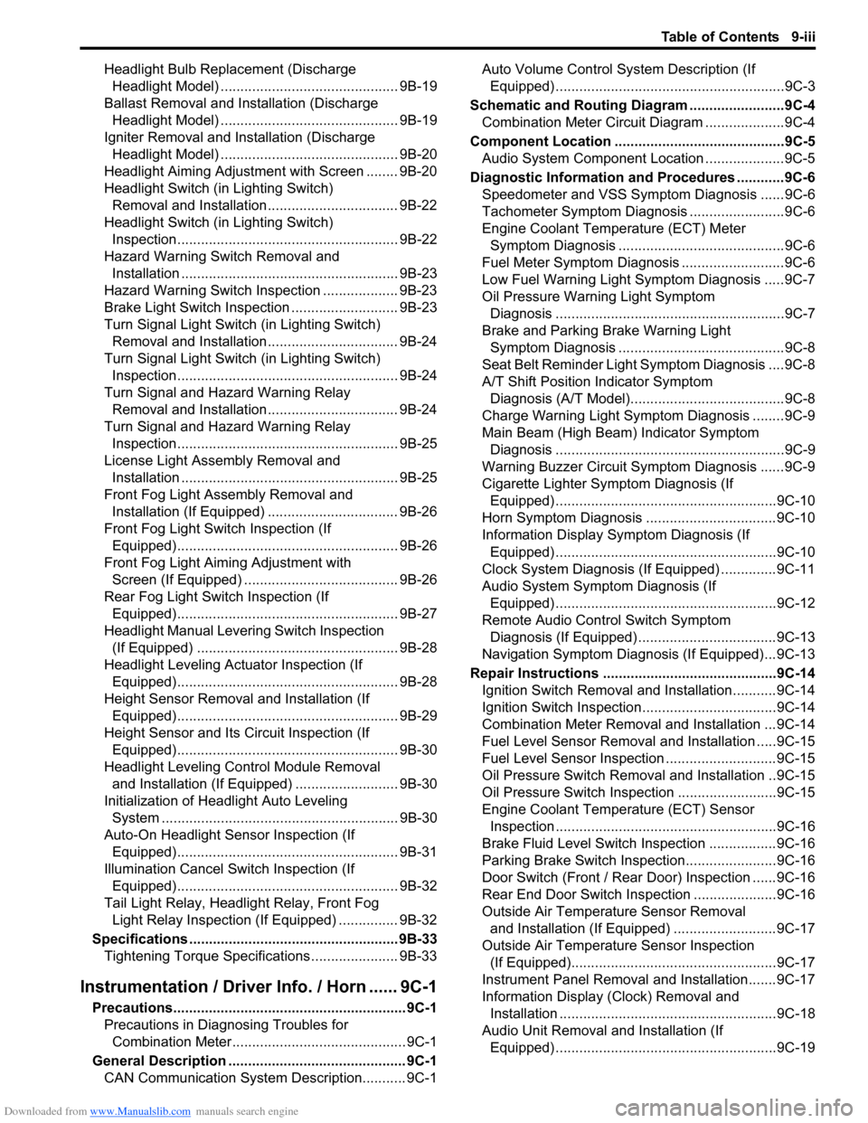
Downloaded from www.Manualslib.com manuals search engine Table of Contents 9-iii
Headlight Bulb Replacement (Discharge
Headlight Model) ............................................. 9B-19
Ballast Removal and Installation (Discharge
Headlight Model) ............................................. 9B-19
Igniter Removal and Installation (Discharge
Headlight Model) ............................................. 9B-20
Headlight Aiming Adjustment with Screen ........ 9B-20
Headlight Switch (in Lighting Switch)
Removal and Installation................................. 9B-22
Headlight Switch (in Lighting Switch)
Inspection........................................................ 9B-22
Hazard Warning Switch Removal and
Installation ....................................................... 9B-23
Hazard Warning Switch Inspection ................... 9B-23
Brake Light Switch Inspection ........................... 9B-23
Turn Signal Light Switch (in Lighting Switch)
Removal and Installation................................. 9B-24
Turn Signal Light Switch (in Lighting Switch)
Inspection........................................................ 9B-24
Turn Signal and Hazard Warning Relay
Removal and Installation................................. 9B-24
Turn Signal and Hazard Warning Relay
Inspection........................................................ 9B-25
License Light Assembly Removal and
Installation ....................................................... 9B-25
Front Fog Light Assembly Removal and
Installation (If Equipped) ................................. 9B-26
Front Fog Light Switch Inspection (If
Equipped)........................................................ 9B-26
Front Fog Light Aiming Adjustment with
Screen (If Equipped) ....................................... 9B-26
Rear Fog Light Switch Inspection (If
Equipped)........................................................ 9B-27
Headlight Manual Levering Switch Inspection
(If Equipped) ................................................... 9B-28
Headlight Leveling Actuator Inspection (If
Equipped)........................................................ 9B-28
Height Sensor Removal and Installation (If
Equipped)........................................................ 9B-29
Height Sensor and Its Circuit Inspection (If
Equipped)........................................................ 9B-30
Headlight Leveling Control Module Removal
and Installation (If Equipped) .......................... 9B-30
Initialization of Headlight Auto Leveling
System ............................................................ 9B-30
Auto-On Headlight Sensor Inspection (If
Equipped)........................................................ 9B-31
Illumination Cancel Switch Inspection (If
Equipped)........................................................ 9B-32
Tail Light Relay, Headlight Relay, Front Fog
Light Relay Inspection (If Equipped) ............... 9B-32
Specifications..................................................... 9B-33
Tightening Torque Specifications ...................... 9B-33
Instrumentation / Driver Info. / Horn ...... 9C-1
Precautions........................................................... 9C-1
Precautions in Diagnosing Troubles for
Combination Meter............................................ 9C-1
General Description ............................................. 9C-1
CAN Communication System Description........... 9C-1Auto Volume Control System Description (If
Equipped) ..........................................................9C-3
Schematic and Routing Diagram ........................9C-4
Combination Meter Circuit Diagram ....................9C-4
Component Location ...........................................9C-5
Audio System Component Location ....................9C-5
Diagnostic Information and Procedures ............9C-6
Speedometer and VSS Symptom Diagnosis ......9C-6
Tachometer Symptom Diagnosis ........................9C-6
Engine Coolant Temperature (ECT) Meter
Symptom Diagnosis ..........................................9C-6
Fuel Meter Symptom Diagnosis ..........................9C-6
Low Fuel Warning Light Symptom Diagnosis .....9C-7
Oil Pressure Warning Light Symptom
Diagnosis ..........................................................9C-7
Brake and Parking Brake Warning Light
Symptom Diagnosis ..........................................9C-8
Seat Belt Reminder Light Symptom Diagnosis ....9C-8
A/T Shift Position Indicator Symptom
Diagnosis (A/T Model).......................................9C-8
Charge Warning Light Symptom Diagnosis ........9C-9
Main Beam (High Beam) Indicator Symptom
Diagnosis ..........................................................9C-9
Warning Buzzer Circuit Symptom Diagnosis ......9C-9
Cigarette Lighter Symptom Diagnosis (If
Equipped) ........................................................9C-10
Horn Symptom Diagnosis .................................9C-10
Information Display Symptom Diagnosis (If
Equipped) ........................................................9C-10
Clock System Diagnosis (If Equipped) ..............9C-11
Audio System Symptom Diagnosis (If
Equipped) ........................................................9C-12
Remote Audio Control Switch Symptom
Diagnosis (If Equipped) ...................................9C-13
Navigation Symptom Diagnosis (If Equipped)...9C-13
Repair Instructions ............................................9C-14
Ignition Switch Removal and Installation...........9C-14
Ignition Switch Inspection..................................9C-14
Combination Meter Removal and Installation ...9C-14
Fuel Level Sensor Removal and Installation .....9C-15
Fuel Level Sensor Inspection ............................9C-15
Oil Pressure Switch Removal and Installation ..9C-15
Oil Pressure Switch Inspection .........................9C-15
Engine Coolant Temperature (ECT) Sensor
Inspection ........................................................9C-16
Brake Fluid Level Switch Inspection .................9C-16
Parking Brake Switch Inspection.......................9C-16
Door Switch (Front / Rear Door) Inspection ......9C-16
Rear End Door Switch Inspection .....................9C-16
Outside Air Temperature Sensor Removal
and Installation (If Equipped) ..........................9C-17
Outside Air Temperature Sensor Inspection
(If Equipped)....................................................9C-17
Instrument Panel Removal and Installation.......9C-17
Information Display (Clock) Removal and
Installation .......................................................9C-18
Audio Unit Removal and Installation (If
Equipped) ........................................................9C-19
Page 1205 of 1556

Downloaded from www.Manualslib.com manuals search engine Wiring Systems: 9A-38
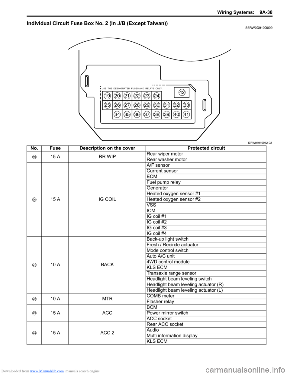
Individual Circuit Fuse Box No. 2 (In J/B (Except Taiwan))S6RW0D910D009
19
25
20
26
34
21
27
35
22
28
36
23
29
37
24
30
38
31
39
32
40
33
41
42USE THE DESINGNATED FUSES AND RELAYS ONLY.
I7RW01910912-02
No. Fuse Description on the cover Protected circuit
15 A RR WIPRear wiper motor
Rear washer motor
15 A IG COILA/F sensor
Current sensor
ECM
Fuel pump relay
Generator
Heated oxygen sensor #1
Heated oxygen sensor #2
VSS
ICM
IG coil #1
IG coil #2
IG coil #3
IG coil #4
10 A BACKBack-up light switch
Fresh / Recircle actuator
Mode control switch
Auto A/C unit
4WD control module
KLS ECM
Transaxle range sensor
Headlight beam leveling switch
Headlight beam leveling actuator (R)
Headlight beam leveling actuator (L)
10 A MTRCOMB meter
Flasher relay
15 A ACCBCM
Power mirror switch
ACC socket
15 A ACC 2Rear ACC socket
Audio
Multi information display
KLS ECM
Page 1282 of 1556

Downloaded from www.Manualslib.com manuals search engine 9A-115 Wiring Systems:
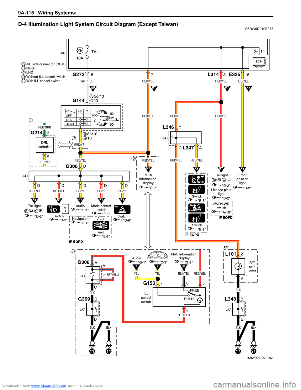
D-4 Illumination Light System Circuit Diagram (Except Taiwan)S6RW0D910E053
BLKBLK
BLK
RED/BLU
RED/BLU
11
J/C
J/C
B
B
14
G309
A
A
C
CG306
BLK/YELRED/YEL
BY
YELYEL
YY
Multi information
display
"G-2"Audio
"G-1""C-3"
ILL
cancel
switch
G150758
4
PUSHFREE
WHT/RED
10ATAIL
29J/B
15G272
G144
1721
RED/YELRED/YELRED/YEL
RED/YELRED/YEL
L3143
BLKBLK
BLK
"D-3"
A/T
RY
Switch
J/C
G306
RED/YEL
RY
RED/YEL
Switch
Auto
unit
IF EQPDIF EQPDIF EQPD
RY
RED/YEL
Mode control
switch
"E-1"Tail light
(L)
"D-2"
"E-2"
"D-6"Switch"B-8"
Switch"B-8"
OFF
TAIL
HEAD+BT T
P
7
RY
RED/YEL
Audio
"G-1"
Navigation
"G-4"
D
D
D D D
RY
RED/YEL
D
RED/YEL
Multi
information
display
"G-2"
RED/YEL
RYRYRY
RYRYWR
Tail light
"D-2"Front
position
light
"D-2"
Licence plate
light
"D-2"
2WD/4WD
switch
"A-10"
RED/YELRED/YEL
RED/YEL
E32516
RY
RY
J/C
B
BL348
J/C
C
C
A
L346
L347
A/T
shift
lever
L1012
5
5or13
13BC
8or10
10BC
J/B side connector (BCM)
RHD
LHD
Without ILL cancel switch
With ILL cancel switch ABCDE
B(R)
C
(R)
B(L)
C
BCM
14A
RED/YEL
D
D
E
DRL
controller
G2143
5
RED/YEL
RED/GRN
E
I6RW0D910919-02