2006 SUZUKI SX4 Power steering
[x] Cancel search: Power steeringPage 1206 of 1556

Downloaded from www.Manualslib.com manuals search engine 9A-39 Wiring Systems:
30 A WIPCOMB switch
Windshield washer motor
Windshield wiper motor
Rear wiper relay
DRL controller
10 A IG1 SIGPower steering control module
A/T relay
Brake light switch
15 A A/B A/B SDM
10 A ABSABS control module
G sensor
10 A TAILCOMB switch
DRL controller
15 A STOP Brake light switch
20 A D/L BCM
15 A 4WD 4WD control module
10 A ST SIG Starting motor relay
15 A S/HSeat heater switch (Driver side)
Seat heater switch (Passenger side)
10 A IG2 SIG Blower fan relay
15 A RR FOG COMB switch
15 A DOMEAudio
BCM
COMB meter
DLC
ECM
Interior light
ICM
TCM
Rear interior light
Luggage compartment light
Main switch (Key switch)
Multi information display
KLS ECM
30 A RR DEFRear defogger relay
Mirror motor (R)
Mirror motor (L)
15 A HORN-HAZHorn relay
Flasher relay
BLANK BLANK BLANK
BLANK BLANK BLANK
30 A P/WPower window main switch
Front power window sub switch
Rear power window sub switch (R)
Rear power window sub switch (L) No. Fuse Description on the cover Protected circuit
Page 1207 of 1556
Downloaded from www.Manualslib.com manuals search engine Wiring Systems: 9A-40
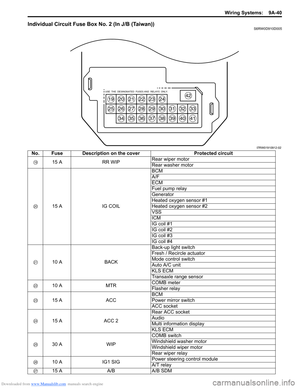
Individual Circuit Fuse Box No. 2 (In J/B (Taiwan))S6RW0D910D005
19
25
20
26
34
21
27
35
22
28
36
23
29
37
24
30
38
31
39
32
40
33
41
42USE THE DESINGNATED FUSES AND RELAYS ONLY.
I7RW01910912-02
No. Fuse Description on the cover Protected circuit
15 A RR WIPRear wiper motor
Rear washer motor
15 A IG COILBCM
A/F
ECM
Fuel pump relay
Generator
Heated oxygen sensor #1
Heated oxygen sensor #2
VSS
ICM
IG coil #1
IG coil #2
IG coil #3
IG coil #4
10 A BACKBack-up light switch
Fresh / Recircle actuator
Mode control switch
Auto A/C unit
KLS ECM
Transaxle range sensor
10 A MTRCOMB meter
Flasher relay
15 A ACCBCM
Power mirror switch
ACC socket
15 A ACC 2Rear ACC socket
Audio
Multi information display
KLS ECM
30 A WIPCOMB switch
Windshield washer motor
Windshield wiper motor
Rear wiper relay
10 A IG1 SIGPower steering control module
A/T relay
15 A A/B A/B SDM
Page 1224 of 1556
Downloaded from www.Manualslib.com manuals search engine 9A-57 Wiring Systems:
System Circuit Diagram
System Circuit DiagramS6RW0D910E001
Refer to “A-1 Cranking System Circuit Diagram”.
Refer to “A-2 Charging System Circuit Diagram”.
Refer to “A-3 Ignition System Circuit Diagram (M15A engine, M16A engine)”.
Refer to “A-3 Ignition System Circuit Diagram (J20A engine)”.
Refer to “A-4 Cooling System Circuit Diagram (M15A engine, M16A engine)”.
Refer to “A-4 Cooling System Circuit Diagram (J20A engine)”.
Refer to “A-5 Engine and A/C Control System Circuit Diagram (M15A engine)”.
Refer to “A-5 Engine and A/C Control System Circuit Diagram (M16A engine)”.
Refer to “A-5 Engine and A/C Control System Circuit Diagram (J20A engine)”.
Refer to “A-6 A/T Control System Circuit Diagram”.
Refer to “A-7 Immobilizer System Circuit Diagram”.
Refer to “A-8 Body Control System Circuit Diagram (Except Taiwan)”.
Refer to “A-8 Body Control System Circuit Diagram (Taiwan)”.
Refer to “A-10 4WD Control System (Except Taiwan)”
Refer to “B-1 Windshield Wiper and Washer Circuit Diagram”.
Refer to “B-2 Rear Wiper and Washer Circuit Diagram (Except Taiwan)”.
Refer to “B-2 Rear Wiper and Washer Circuit Diagram (Taiwan)”.
Refer to “B-3 Rear Defogger Circuit Diagram (Except Taiwan)”.
Refer to “B-3 Rear Defogger Circuit Diagram (Taiwan)”.
Refer to “B-4 Power Window Circuit Diagram”.
Refer to “B-5 Power Door Lock Circuit Diagram (Except Taiwan)”.
Refer to “B-5 Power Door Lock Circuit Diagram (Taiwan)”.
Refer to “B-6 Power Mirror Circuit Diagram (Except Taiwan)”.
Refer to “B-6 Power Mirror Circuit Diagram (Taiwan)”.
Refer to “B-7 Horn Circuit Diagram”.
Refer to “B-8 Seat Heater Circuit Diagram”.
Refer to “B-9 Keyless Start System Circuit Diagram”
Refer to “C-1 Combination Meter Circuit Diagram (Meter)”.
Refer to “C-2 Combination Meter Circuit Diagram (Indicator)”.
Refer to “C-3 Combination Meter Circuit Diagram (Warning Light)”.
Refer to “D-1 Headlight System Circuit Diagram (Except Taiwan)”.
Refer to “D-1 Headlight System Circuit Diagram (Taiwan)”.
Refer to “D-2 Position, Tail and Licence Plate Light System Circuit Diagram (Except Taiwan)”.
Refer to “D-2 Position, Tail and Licence Plate Light System Circuit Diagram (Taiwan)”.
Refer to “D-3 Front Fog Light System Circuit Diagram (Except Taiwan)”.
Refer to “D-3 Front Fog Light System Circuit Diagram (Taiwan)”.
Refer to “D-4 Illumination Light System Circuit Diagram (Except Taiwan)”.
Refer to “D-4 Illumination Light System Circuit Diagram (Taiwan)”.
Refer to “D-5 Interior Light System Circuit Diagram (Except Taiwan)”.
Refer to “D-5 Interior Light System Circuit Diagram (Taiwan)”.
Refer to “D-6 Turn Signal and Hazard Warning Light System Circuit Diagram (Except Taiwan)”.
Refer to “D-6 Turn Signal and Hazard Warning Light System Circuit Diagram (Taiwan)”.
Refer to “D-7 Brake Light System Circuit Diagram”.
Refer to “D-8 Back-Up Light System Circuit Diagram”.
Refer to “D-9 Headlight Beam Leveling System Circuit Diagram (Manual Leveling)”.
Refer to “D-10 Rear Fog Light Circuit Diagram”.
Refer to “E-1 Heater System Circuit Diagram”.
Refer to “E-2 Auto A/C System Circuit Diagram”.
Refer to “F-1 Air-Bag System Circuit Diagram (4ch)”.
Refer to “F-1 Air-Bag System Circuit Diagram (8ch)”.
Refer to “F-2 Anti-Lock Brake System Circuit Diagram”.
Refer to “F-4 Power Steering System Circuit Diagram”.
Refer to “G-1 Audio System Circuit Diagram”.
Refer to “G-2 Multi Information Display / Accessory Socket System Circuit Diagram”.
Refer to “G-4 Navigation System Circuit Diagram”.
Page 1303 of 1556
Downloaded from www.Manualslib.com manuals search engine Wiring Systems: 9A-136
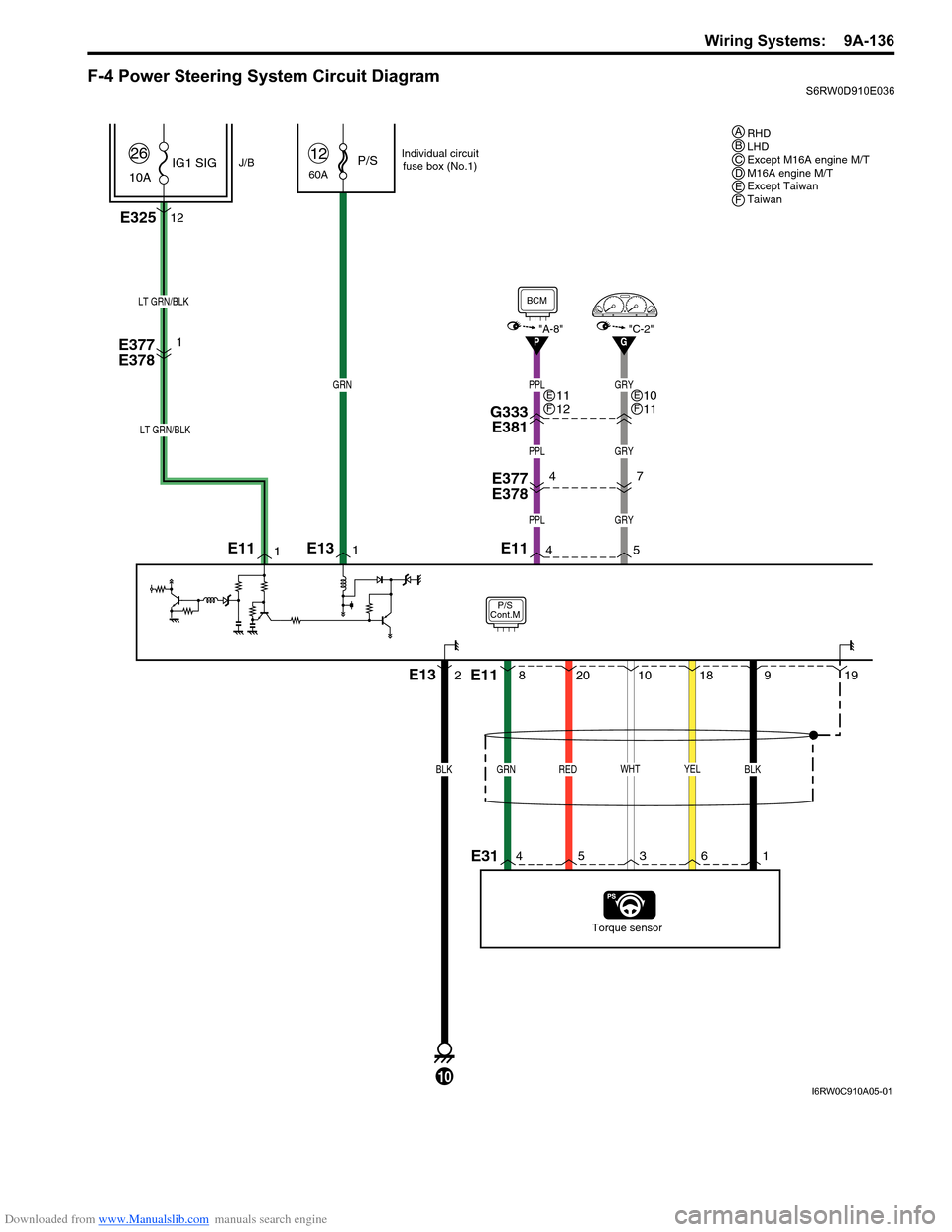
F-4 Power Steering System Circuit DiagramS6RW0D910E036
P/S
Cont.M
60AP/S12
E32512
J/B10AIG1 SIG
26
RED
20
E377
E378
Torque sensor
BLK
E13
10
GRN
LT GRN/BLK
WHT
10
GRN
8
YEL
18
BLK
919
1
2 1E11
PPL
PPL
4
LT GRN/BLK
1
E377
E3784
PPL
G333
E381
E31
E13
E11 E11
Individual circuit
fuse box (No.1)
1 6 3 5 4
"C-2"
BCM
"A-8"P
GRY
GRY
5
7
GRY
G
11
12EF10
11EF
RHD
LHD
Except M16A engine M/T
M16A engine M/T
Except Taiwan
Taiwan ABCDEF
I6RW0C910A05-01
Page 1334 of 1556
Downloaded from www.Manualslib.com manuals search engine 9B-15 Lighting Systems:
Auto-On Headlight Operation Inspection (If
Equipped)
S6RW0D9204021
1) Turn ignition switch to ON position and then turn
lighting switch to “AUTO” position.
2) Check headlights for operation as follows. If
headlights do not turn ON or OFF, go to “Inspection
of Auto-On Headlight Controller and Its Circuit (If
Equipped)”.
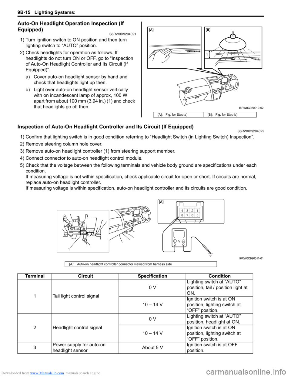
a) Cover auto-on headlight sensor by hand and
check that headlights light up then.
b) Light over auto-on headlight sensor vertically
with on incandescent lamp of approx, 100 W
apart from about 100 mm (3.94 in.) (1) and check
that headlights go off then.
Inspection of Auto-On Headlight Controller and Its Circuit (If Equipped)S6RW0D9204022
1) Confirm that lighting switch is in good condition referring to “Headlight Switch (in Lighting Switch) Inspection”.
2) Remove steering column hole cover.
3) Remove auto-on headlight controller (1) from steering support member.
4) Connect connector to auto-on headlight control module.
5) Check that the voltage between the following terminals and vehicle body ground are specifications under each
condition.
If measuring voltage is not within specification, check applicable circuit for open or short. If circuits are normal,
replace auto-on headlight controller.
If measuring voltage is within specification, auto-on headlight controller and its circuits are good condition.
[A]: Fig. for Step a) [B]: Fig. for Step b)
[A] [B]
1
I6RW0C920010-02
1
4321
8765
V
[A]
I6RW0C920011-01
[A]: Auto-on headlight controller connector viewed from harness side
Terminal Circuit Specification Condition
1 Tail light control signal0 VLighting switch at “AUTO”
position, tail / position light at
ON.
10 – 14 VIgnition switch is at ON
position, lighting switch at
“OFF” position.
2 Headlight control signal0 VLighting switch at “AUTO”
position, headlight at ON.
10 – 14 VIgnition switch is at ON
position, lighting switch at
“OFF” position.
3Power supply for auto-on
headlight sensorAbout 5 VIgnition switch is at OFF
position.
Page 1349 of 1556
Downloaded from www.Manualslib.com manuals search engine Lighting Systems: 9B-30
Height Sensor and Its Circuit Inspection (If
Equipped)
S6RW0D9206028
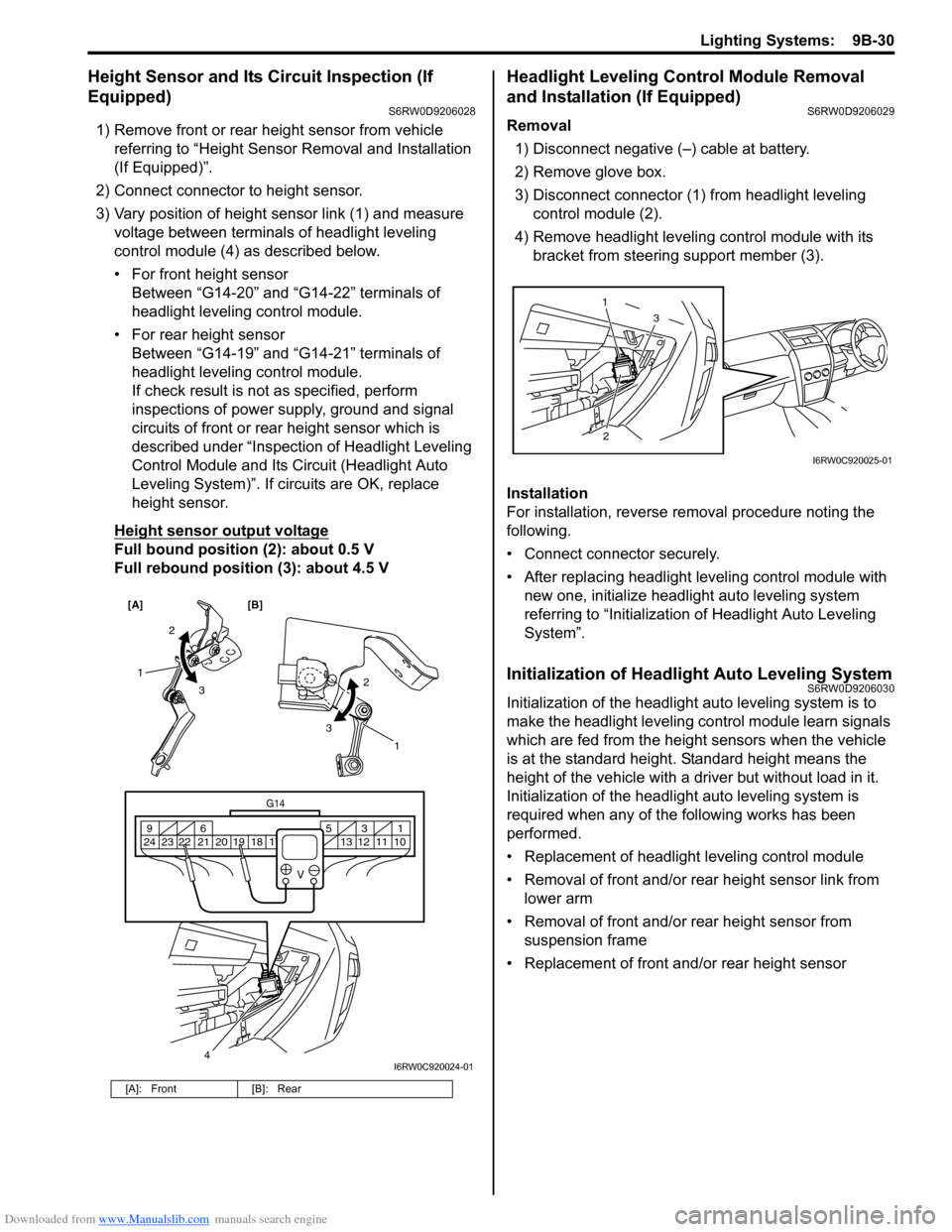
1) Remove front or rear height sensor from vehicle
referring to “Height Sensor Removal and Installation
(If Equipped)”.
2) Connect connector to height sensor.
3) Vary position of height sensor link (1) and measure
voltage between terminals of headlight leveling
control module (4) as described below.
• For front height sensor
Between “G14-20” and “G14-22” terminals of
headlight leveling control module.
• For rear height sensor
Between “G14-19” and “G14-21” terminals of
headlight leveling control module.
If check result is not as specified, perform
inspections of power supply, ground and signal
circuits of front or rear height sensor which is
described under “Inspection of Headlight Leveling
Control Module and Its Circuit (Headlight Auto
Leveling System)”. If circuits are OK, replace
height sensor.
Height sensor output voltage
Full bound position (2): about 0.5 V
Full rebound position (3): about 4.5 V
Headlight Leveling Control Module Removal
and Installation (If Equipped)
S6RW0D9206029
Removal
1) Disconnect negative (–) cable at battery.
2) Remove glove box.
3) Disconnect connector (1) from headlight leveling
control module (2).
4) Remove headlight leveling control module with its
bracket from steering support member (3).
Installation
For installation, reverse removal procedure noting the
following.
• Connect connector securely.
• After replacing headlight leveling control module with
new one, initialize headlight auto leveling system
referring to “Initialization of Headlight Auto Leveling
System”.
Initialization of Headlight Auto Leveling SystemS6RW0D9206030
Initialization of the headlight auto leveling system is to
make the headlight leveling control module learn signals
which are fed from the height sensors when the vehicle
is at the standard height. Standard height means the
height of the vehicle with a driver but without load in it.
Initialization of the headlight auto leveling system is
required when any of the following works has been
performed.
• Replacement of headlight leveling control module
• Removal of front and/or rear height sensor link from
lower arm
• Removal of front and/or rear height sensor from
suspension frame
• Replacement of front and/or rear height sensor
[A]: Front [B]: Rear
[A] [B]
4
G14
10 11 12 13 16 17 18 19 2031 5 6 9
21 22 23 24
V
2
3 1
2
3
1
I6RW0C920024-01
23 1
I6RW0C920025-01
Page 1407 of 1556
Downloaded from www.Manualslib.com manuals search engine Glass / Windows / Mirrors: 9E-22
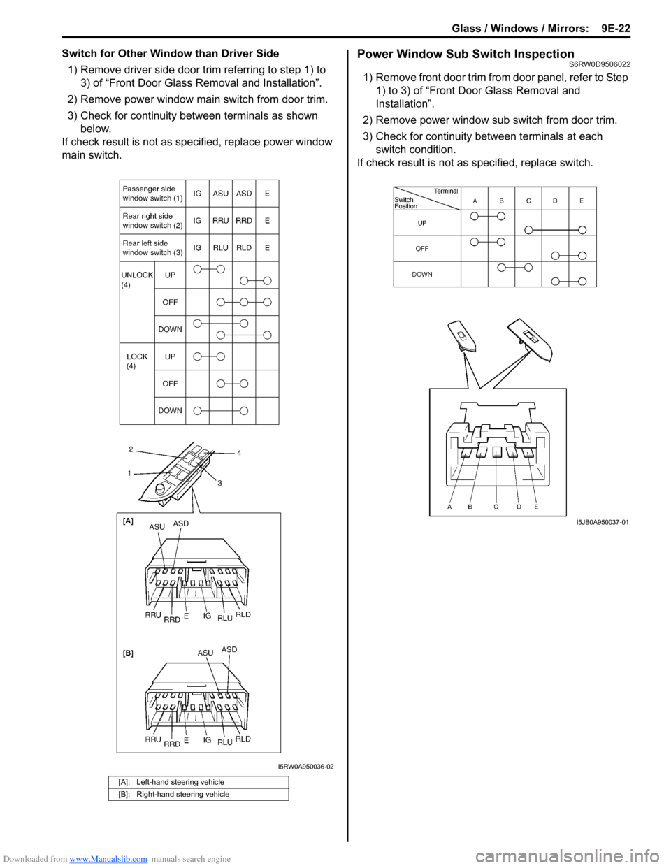
Switch for Other Window than Driver Side
1) Remove driver side door trim referring to step 1) to
3) of “Front Door Glass Removal and Installation”.
2) Remove power window main switch from door trim.
3) Check for continuity between terminals as shown
below.
If check result is not as specified, replace power window
main switch.Power Window Sub Switch InspectionS6RW0D9506022
1) Remove front door trim from door panel, refer to Step
1) to 3) of “Front Door Glass Removal and
Installation”.
2) Remove power window sub switch from door trim.
3) Check for continuity between terminals at each
switch condition.
If check result is not as specified, replace switch.
[A]: Left-hand steering vehicle
[B]: Right-hand steering vehicle
I5RW0A950036-02
I5JB0A950037-01
Page 1472 of 1556
Downloaded from www.Manualslib.com manuals search engine 10-ii Table of Contents
Immobilizer Indicator Light Remains ON after
Engine Start ..................................................10C-10
DTC P1614: Transponder Response Error .....10C-10
DTC P1615: Steering Lock Unit
Communication Error ....................................10C-11
DTC P1616: Unregistered Keyless Start
Control Module ..............................................10C-12
DTC P1618: Keyless Start Control Module
CAN Communication Error............................10C-13
DTC P1621: Immobilizer Communication
Line Error ......................................................10C-13
DTC P1622: EEPROM Reading / Writing
Error ..............................................................10C-14
DTC P1623: Unregistered Transponder .........10C-14
DTC P1625: Immobilizer Antenna Error..........10C-15
DTC P1636: Immobilizer Information
Registration Failure .......................................10C-15
DTC P1638: Immobilizer Information
Mismatched ...................................................10C-16
Inspection of ICM and Its Circuit .....................10C-17
Repair Instructions ..........................................10C-19
ICM Removal and Installation .........................10C-19
Registration of the Ignition Key .......................10C-19
Procedure after ECM Replacement ................10C-19
Special Tools and Equipment .........................10C-20
Special Tool ....................................................10C-20
Keyless Start System .............................10E-1
General Description ........................................... 10E-1
Keyless Start System Description ..................... 10E-1
Parts and Functions .......................................... 10E-2
Keyless Engine Start Function .......................... 10E-3
Door Lock Function of Keyless Start System .... 10E-4
Operation Area of Remote Controller................ 10E-5
Alarm Function .................................................. 10E-6
CAN Communication System Description......... 10E-6
Schematic and Routing Diagram ...................... 10E-7
Keyless Start System Electric Wiring Circuit
Diagram .......................................................... 10E-7
Diagnostic Information and Procedures .......... 10E-8
Precautions in Diagnosing Troubles ................. 10E-8
Self-Diagnosis Function .................................... 10E-8
Keyless Start System Diagnosis Introduction ... 10E-8
Keyless Start System Check ............................. 10E-9
Customer Questionnaire (Example) ................ 10E-10Key Indicator Light Check ............................... 10E-10
DTC Check...................................................... 10E-11
DTC Table ....................................................... 10E-12
DTC Clearance ............................................... 10E-12
Keyless Start System Symptom Diagnosis ..... 10E-13
Keyless Start System Operation Inspection .... 10E-14
Door Lock Operation (Keyless Start System) . 10E-14
Inspection of Keyless Start Control Module
and Its Circuits .............................................. 10E-14
No DTC Detection After Performing DTC
Check ............................................................ 10E-20
Key Indicator Light Circuit Check (Key
Indicator Light Doesn’t Light when Ignition
Knob Switch is Pushed) ................................ 10E-21
Keyless Start Control Module Power and
Ground Circuit Check .................................... 10E-23
DTC No. 11: Communication Error with
Steering Lock Unit ......................................... 10E-24
DTC No. 13 / No. 14: Release Signal Error
from Steering Lock Unit / Steering Lock Unit
Malfunction .................................................... 10E-25
DTC No. 21 / No. 22: Internal Error of Keyless
Start Control Module (EEPROM Reading
Error) / (EEPROM Writing Error) ................... 10E-25
DTC No. 31: Lost Communication with BCM .. 10E-26
DTC No. 33: Control Module Communication
Bus Off .......................................................... 10E-26
DTC No. 51 / No. 52 / No. 53: Driver Side /
Passenger Side / Rear End Door Request
Switch Failure................................................ 10E-26
Repair Instructions .......................................... 10E-27
Antennas and Request Switches Removal
and Installation .............................................. 10E-27
Front Door (Driver and Passenger Side), Rear
End Door Request Switch Inspection............ 10E-28
Steering Lock Unit Removal and Installation .. 10E-28
Steering Lock Unit Inspection ......................... 10E-28
Front Door Lock Switch Inspection ................. 10E-28
Keyless Start Control Module Removal and
Installation ..................................................... 10E-29
Remote Controller Inspection.......................... 10E-29
Replacement of Remote Controller Battery .... 10E-29
Registration Procedure for Remote Controller
ID Code ......................................................... 10E-30
Keyless Start Registration ............................... 10E-31