2006 SUZUKI SX4 Power steering
[x] Cancel search: Power steeringPage 1076 of 1556
Downloaded from www.Manualslib.com manuals search engine 8B-37 Air Bag System:
NOTE
Upon completion of inspection and repair work, perform the following items.
• Reconnect all air bag system components and ensure all components are properly mounted.
• Clear DTCs referring to “DTC Clearance”, if any.
• Repeat “Air Bag Diagnostic System Check” to confirm that the trouble has been corrected.
DTC B1034: Driver Air Bag Circuit Shorted to Power SupplyS6RW0D8204021
Wiring Diagram
Refer to “DTC B1031: Driver Air Bag Circuit High Resistance”.
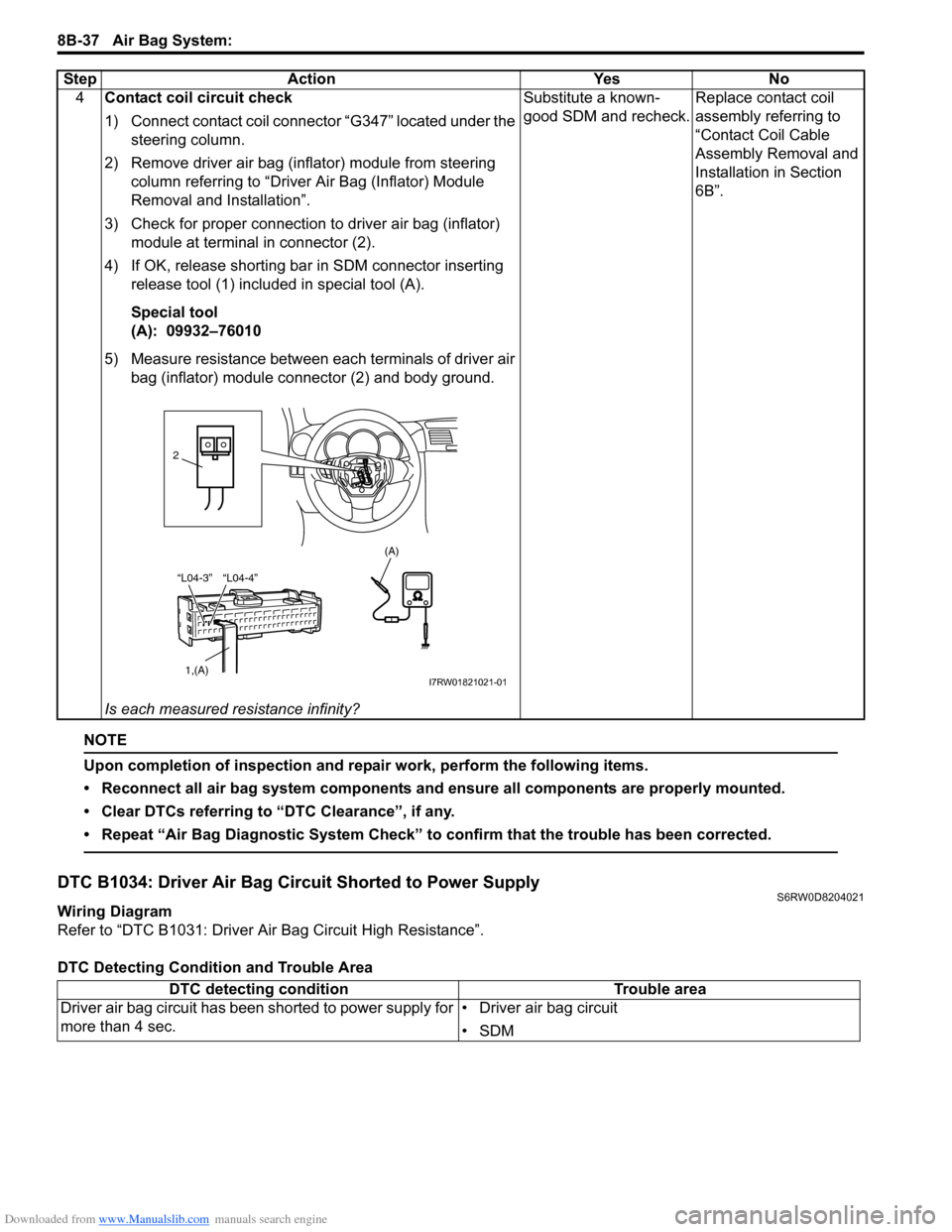
DTC Detecting Condition and Trouble Area4Contact coil circuit check
1) Connect contact coil connector “G347” located under the
steering column.
2) Remove driver air bag (inflator) module from steering
column referring to “Driver Air Bag (Inflator) Module
Removal and Installation”.
3) Check for proper connection to driver air bag (inflator)
module at terminal in connector (2).
4) If OK, release shorting bar in SDM connector inserting
release tool (1) included in special tool (A).
Special tool
(A): 09932–76010
5) Measure resistance between each terminals of driver air
bag (inflator) module connector (2) and body ground.
Is each measured resistance infinity?Substitute a known-
good SDM and recheck.Replace contact coil
assembly referring to
“Contact Coil Cable
Assembly Removal and
Installation in Section
6B”. Step Action Yes No
“L04-4” “L04-3”
1,(A)
(A)
2
I7RW01821021-01
DTC detecting condition Trouble area
Driver air bag circuit has been shorted to power supply for
more than 4 sec.• Driver air bag circuit
•SDM
Page 1077 of 1556
Downloaded from www.Manualslib.com manuals search engine Air Bag System: 8B-38
DTC Troubleshooting
Step Action Yes No
1Was “Air Bag Diagnostic System Check Flow” performed?Go to Step 2. Go to “Air Bag
Diagnostic System
Check Flow”.
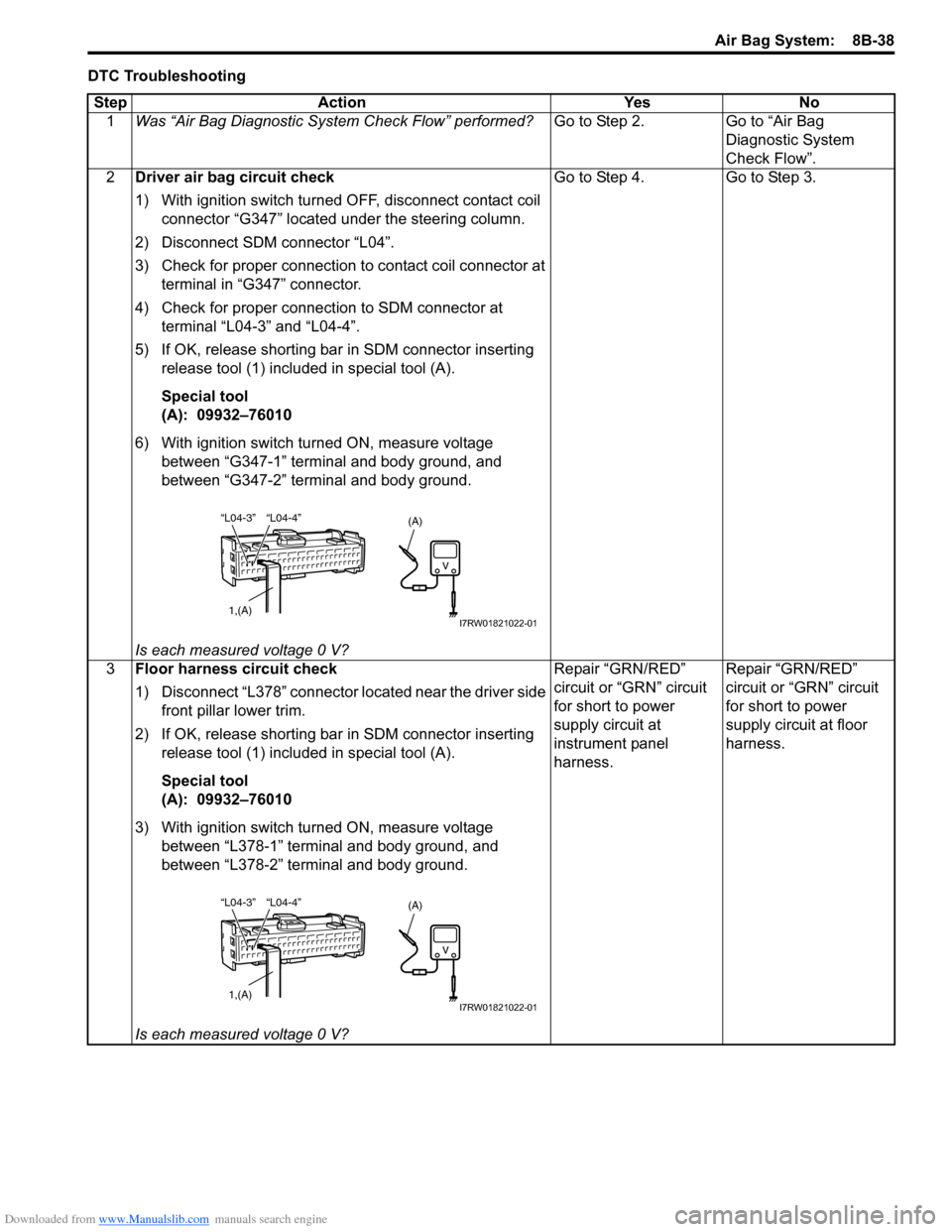
2Driver air bag circuit check
1) With ignition switch turned OFF, disconnect contact coil
connector “G347” located under the steering column.
2) Disconnect SDM connector “L04”.
3) Check for proper connection to contact coil connector at
terminal in “G347” connector.
4) Check for proper connection to SDM connector at
terminal “L04-3” and “L04-4”.
5) If OK, release shorting bar in SDM connector inserting
release tool (1) included in special tool (A).
Special tool
(A): 09932–76010
6) With ignition switch turned ON, measure voltage
between “G347-1” terminal and body ground, and
between “G347-2” terminal and body ground.
Is each measured voltage 0 V?Go to Step 4. Go to Step 3.
3Floor harness circuit check
1) Disconnect “L378” connector located near the driver side
front pillar lower trim.
2) If OK, release shorting bar in SDM connector inserting
release tool (1) included in special tool (A).
Special tool
(A): 09932–76010
3) With ignition switch turned ON, measure voltage
between “L378-1” terminal and body ground, and
between “L378-2” terminal and body ground.
Is each measured voltage 0 V?Repair “GRN/RED”
circuit or “GRN” circuit
for short to power
supply circuit at
instrument panel
harness.Repair “GRN/RED”
circuit or “GRN” circuit
for short to power
supply circuit at floor
harness.
“L04-4” “L04-3”
1,(A)
(A)
I7RW01821022-01
“L04-4” “L04-3”
1,(A)
(A)
I7RW01821022-01
Page 1086 of 1556
Downloaded from www.Manualslib.com manuals search engine 8B-47 Air Bag System:
NOTE
Upon completion of inspection and repair work, perform the following items.
• Reconnect all air bag system components and ensure all components are properly mounted.
• Clear DTCs referring to “DTC Clearance”, if any.
• Repeat “Air Bag Diagnostic System Check” to confirm that the trouble has been corrected.
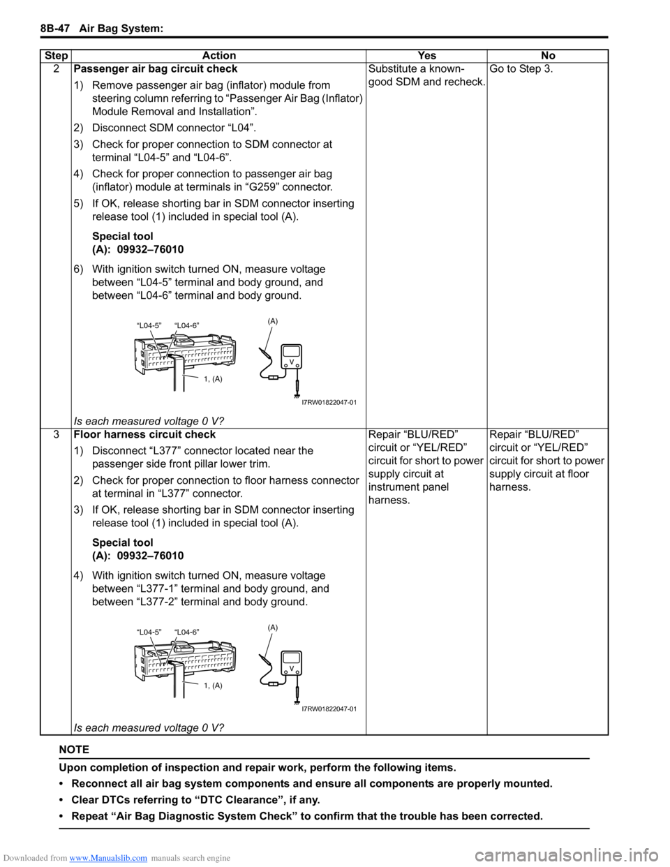
2Passenger air bag circuit check
1) Remove passenger air bag (inflator) module from
steering column referring to “Passenger Air Bag (Inflator)
Module Removal and Installation”.
2) Disconnect SDM connector “L04”.
3) Check for proper connection to SDM connector at
terminal “L04-5” and “L04-6”.
4) Check for proper connection to passenger air bag
(inflator) module at terminals in “G259” connector.
5) If OK, release shorting bar in SDM connector inserting
release tool (1) included in special tool (A).
Special tool
(A): 09932–76010
6) With ignition switch turned ON, measure voltage
between “L04-5” terminal and body ground, and
between “L04-6” terminal and body ground.
Is each measured voltage 0 V?Substitute a known-
good SDM and recheck.Go to Step 3.
3Floor harness circuit check
1) Disconnect “L377” connector located near the
passenger side front pillar lower trim.
2) Check for proper connection to floor harness connector
at terminal in “L377” connector.
3) If OK, release shorting bar in SDM connector inserting
release tool (1) included in special tool (A).
Special tool
(A): 09932–76010
4) With ignition switch turned ON, measure voltage
between “L377-1” terminal and body ground, and
between “L377-2” terminal and body ground.
Is each measured voltage 0 V?Repair “BLU/RED”
circuit or “YEL/RED”
circuit for short to power
supply circuit at
instrument panel
harness.Repair “BLU/RED”
circuit or “YEL/RED”
circuit for short to power
supply circuit at floor
harness. Step Action Yes No
1, (A)
“L04-6” “L04-5”(A)
I7RW01822047-01
1, (A)
“L04-6” “L04-5”(A)
I7RW01822047-01
Page 1162 of 1556
Downloaded from www.Manualslib.com manuals search engine 9-ii Table of Contents
B-9 Keyless Start System Circuit Diagram...... 9A-103
C-1 Combination Meter Circuit Diagram
(Meter) .......................................................... 9A-104
C-2 Combination Meter Circuit Diagram
(Indicator) ...................................................... 9A-105
C-3 Combination Meter Circuit Diagram
(Warning Light) ............................................. 9A-106
D-1 Headlight System Circuit Diagram
(Except Taiwan) ............................................ 9A-108
D-1 Headlight System Circuit Diagram
(Taiwan) ........................................................ 9A-110
D-2 Position, Tail and Licence Plate Light
System Circuit Diagram (Except Taiwan) ..... 9A-111
D-2 Position, Tail and Licence Plate Light
System Circuit Diagram (Taiwan) ................. 9A-112
D-3 Front Fog Light System Circuit Diagram
(Except Taiwan) ............................................ 9A-113
D-3 Front Fog Light System Circuit Diagram
(Taiwan) ........................................................ 9A-114
D-4 Illumination Light System Circuit Diagram
(Except Taiwan) ............................................ 9A-115
D-4 Illumination Light System Circuit Diagram
(Taiwan) ........................................................ 9A-116
D-5 Interior Light System Circuit Diagram
(Except Taiwan) ............................................ 9A-117
D-5 Interior Light System Circuit Diagram
(Taiwan) ........................................................ 9A-118
D-6 Turn Signal and Hazard Warning Light
System Circuit Diagram (Except Taiwan) ..... 9A-119
D-6 Turn Signal and Hazard Warning Light
System Circuit Diagram (Taiwan) ................. 9A-121
D-7 Brake Light System Circuit Diagram ........ 9A-123
D-8 Back-Up Light System Circuit Diagram .... 9A-124
D-9 Headlight Beam Leveling System Circuit
Diagram (Manual Leveling)........................... 9A-125
D-10 Rear Fog Light Circuit Diagram .............. 9A-126
E-1 Heater System Circuit Diagram ................ 9A-127
E-2 Auto A/C System Circuit Diagram ............ 9A-129
F-1 Air-Bag System Circuit Diagram (4ch) ...... 9A-131
F-1 Air-Bag System Circuit Diagram (8ch) ...... 9A-132
F-2 Anti-Lock Brake System Circuit Diagram.. 9A-134
F-4 Power Steering System Circuit Diagram .. 9A-136
G-1 Audio System Circuit Diagram ................. 9A-138
G-2 Multi Information Display / Accessory
Socket System Circuit Diagram .................... 9A-140
G-4 Navigation System Circuit Diagram ......... 9A-141
List of Connector .............................................9A-143
List of Connectors ........................................... 9A-143
C Connector .................................................... 9A-143
E Connector .................................................... 9A-145
G Connector .................................................... 9A-146
J Connector ..................................................... 9A-149
K Connector .................................................... 9A-149
L Connector..................................................... 9A-150
O Connector .................................................... 9A-152
Q Connector (8ch)........................................... 9A-152
R Connector .................................................... 9A-152
S Connector .................................................... 9A-152
Lighting Systems .................................... 9B-1
Precautions ...........................................................9B-1
Precautions for Discharge Headlight Service
(If Equipped)...................................................... 9B-1
Precautions in Diagnosing Troubles
(Headlight Auto Leveling System) ..................... 9B-1
General Description .............................................9B-1
Discharge Headlight Description (If
Equipped) .......................................................... 9B-1
Headlight Auto Leveling System Description
(If Equipped)...................................................... 9B-2
Auto-On Headlight System Description (If
Equipped) .......................................................... 9B-4
Schematic and Routing Diagram ........................9B-5
Headlight Auto Leveling System Wiring
Circuit Diagram ................................................. 9B-5
Component Location ...........................................9B-6
Lighting System Components Location............... 9B-6
Interior Light System Location............................. 9B-7
Diagnostic Information and Procedures ............9B-7
Self-Diagnosis Function for Headlight Auto
Leveling System ................................................ 9B-7
Headlight Leveling Warning Light Check ............ 9B-8
Headlight Symptom Diagnosis (Discharge
Headlight Model) ............................................... 9B-8
Headlight Symptom diagnosis (Other than
Discharge Headlight Model) .............................. 9B-9
Auto-On Headlight System Symptom
Diagnosis (If Equipped) ..................................... 9B-9
DRL System Symptom Diagnosis (If
Equipped) ........................................................ 9B-10
Headlight Auto Leveling System Symptom
Diagnosis (If Equipped) ................................... 9B-10
Headlight Manual Leveling System Symptom
Diagnosis (If Equipped) ................................... 9B-10
Turn Signal and Hazard Warning Light
Symptom Diagnosis ........................................ 9B-11
Clearance, Tail and License Plate Light
Symptom Diagnosis ........................................ 9B-11
Back-Up Light Symptom Diagnosis................... 9B-12
Brake Light Symptom Diagnosis ....................... 9B-12
Front Fog Light Symptom Diagnosis (If
Equipped) ........................................................ 9B-12
Rear Fog Light Symptom Diagnosis (If
Equipped) ........................................................ 9B-12
Illumination Cancel System Symptom
Diagnosis (If Equipped) ................................... 9B-13
Interior Light Symptom Diagnosis ..................... 9B-13
DRL Operation Inspection (If Equipped) ........... 9B-13
Inspection of DRL Controller and Its Circuits
(If Equipped).................................................... 9B-13
Auto-On Headlight Operation Inspection (If
Equipped) ........................................................ 9B-15
Inspection of Auto-On Headlight Controller
and Its Circuit (If Equipped)............................. 9B-15
Inspection of Headlight Leveling Control
Module and Its Circuit (Headlight Auto
Leveling System)............................................. 9B-16
Repair Instructions ............................................9B-18
Headlight Housing Removal and Installation .... 9B-18
Page 1170 of 1556
Downloaded from www.Manualslib.com manuals search engine 9A-3 Wiring Systems:
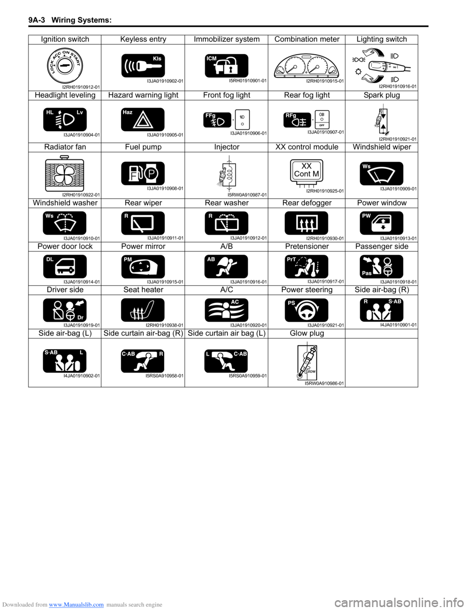
Ignition switch Keyless entry Immobilizer system Combination meter Lighting switch
Headlight leveling Hazard warning light Front fog light Rear fog light Spark plug
Radiator fan Fuel pump Injector XX control module Windshield wiper
Windshield washer Rear wiper Rear washer Rear defogger Power window
Power door lock Power mirror A/B Pretensioner Passenger side
Driver side Seat heater A/C Power steering Side air-bag (R)
Side air-bag (L) Side curtain air-bag (R) Side curtain air bag (L) Glow plug
I2RH01910912-01I3JA01910902-01I5RH01910901-01I2RH01910915-01I2RH01910916-01
I3JA01910904-01I3JA01910905-01I3JA01910906-01I3JA01910907-01I2RH01910921-01
I2RH01910922-01I3JA01910908-01I5RW0A910987-01
XX
Cont M
I2RH01910925-01I3JA01910909-01
I3JA01910910-01I3JA01910911-01I3JA01910912-01I2RH01910930-01I3JA01910913-01
I3JA01910914-01I3JA01910915-01I3JA01910916-01I3JA01910917-01I3JA01910918-01
I3JA01910919-01I2RH01910938-01I3JA01910920-01I3JA01910921-01I4JA01910901-01
I4JA01910902-01I5RS0A910958-01I5RS0A910959-01
I5RW0A910986-01
Page 1186 of 1556
Downloaded from www.Manualslib.com manuals search engine 9A-19 Wiring Systems:
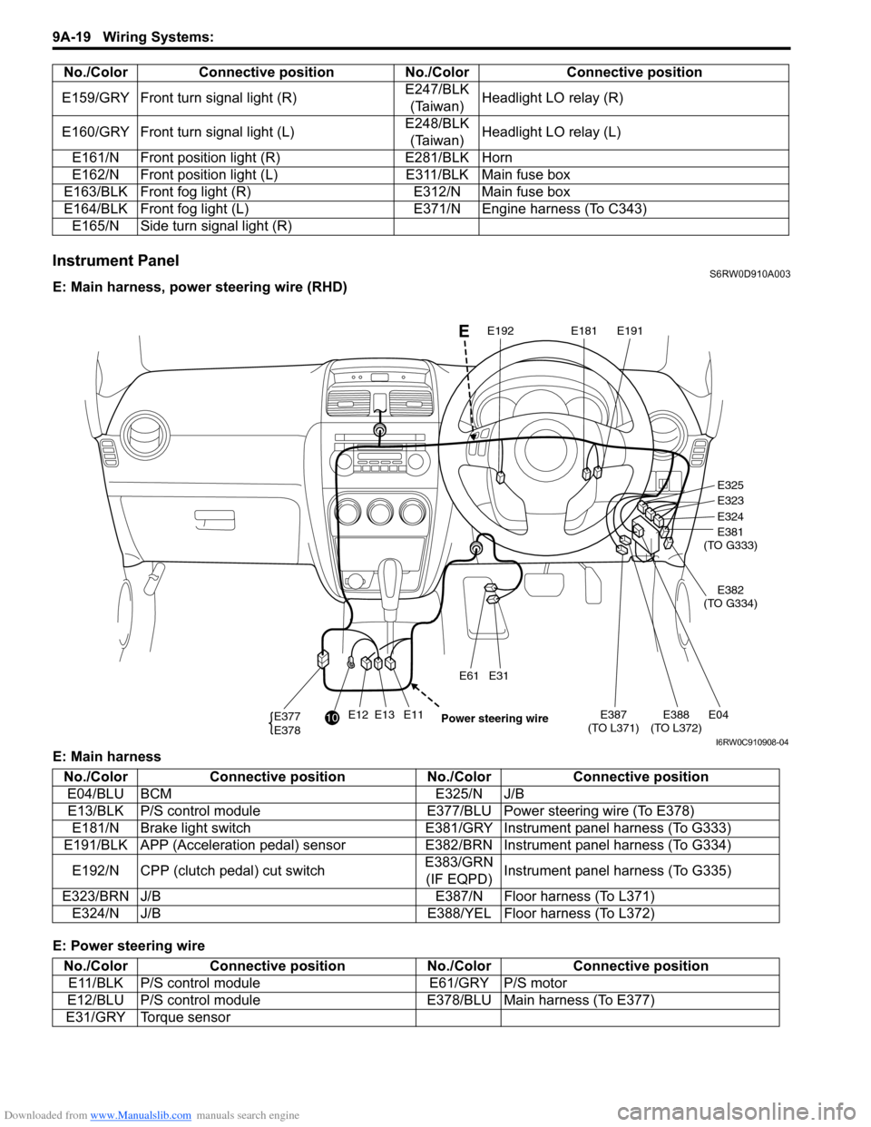
Instrument PanelS6RW0D910A003
E: Main harness, power steering wire (RHD)
E: Main harness
E: Power steering wireE159/GRY Front turn signal light (R)E247/BLK
(Taiwan)Headlight LO relay (R)
E160/GRY Front turn signal light (L)E248/BLK
(Taiwan)Headlight LO relay (L)
E161/N Front position light (R) E281/BLK Horn
E162/N Front position light (L) E311/BLK Main fuse box
E163/BLK Front fog light (R) E312/N Main fuse box
E164/BLK Front fog light (L) E371/N Engine harness (To C343)
E165/N Side turn signal light (R) No./Color Connective position No./Color Connective position
E12E13E11E387
(TO L371)E04E388
(TO L372)
E31E61
E377
E378
E325
E323
E324
E381
(TO G333)
E382
(TO G334)
E191E181E192
10
Power steering wire
E
I6RW0C910908-04
No./Color Connective position No./Color Connective position
E04/BLU BCM E325/N J/B
E13/BLK P/S control module E377/BLU Power steering wire (To E378)
E181/N Brake light switch E381/GRY Instrument panel harness (To G333)
E191/BLK APP (Acceleration pedal) sensor E382/BRN Instrument panel harness (To G334)
E192/N CPP (clutch pedal) cut switchE383/GRN
(IF EQPD)Instrument panel harness (To G335)
E323/BRN J/B E387/N Floor harness (To L371)
E324/N J/B E388/YEL Floor harness (To L372)
No./Color Connective position No./Color Connective position
E11/BLK P/S control module E61/GRY P/S motor
E12/BLU P/S control module E378/BLU Main harness (To E377)
E31/GRY Torque sensor
Page 1187 of 1556
Downloaded from www.Manualslib.com manuals search engine Wiring Systems: 9A-20
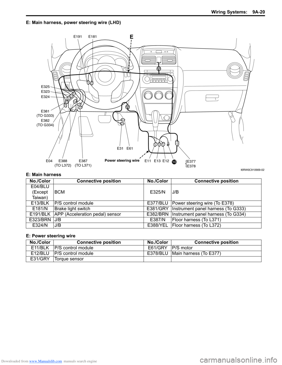
E: Main harness, power steering wire (LHD)
E: Main harness
E: Power steering wire
E12E13E11E387
(TO L371)E04E388
(TO L372)
E31E61
E377
E378
E325
E323
E324
E381
(TO G333)
E382
(TO G334)
E191E181
10 Power steering wire
E
I6RW0C910909-02
No./Color Connective position No./Color Connective position
E04/BLU
(Except
Taiwan)BCM E325/N J/B
E13/BLK P/S control module E377/BLU Power steering wire (To E378)
E181/N Brake light switch E381/GRY Instrument panel harness (To G333)
E191/BLK APP (Acceleration pedal) sensor E382/BRN Instrument panel harness (To G334)
E323/BRN J/B E387/N Floor harness (To L371)
E324/N J/B E388/YEL Floor harness (To L372)
No./Color Connective position No./Color Connective position
E11/BLK P/S control module E61/GRY P/S motor
E12/BLU P/S control module E378/BLU Main harness (To E377)
E31/GRY Torque sensor
Page 1204 of 1556
Downloaded from www.Manualslib.com manuals search engine 9A-37 Wiring Systems:
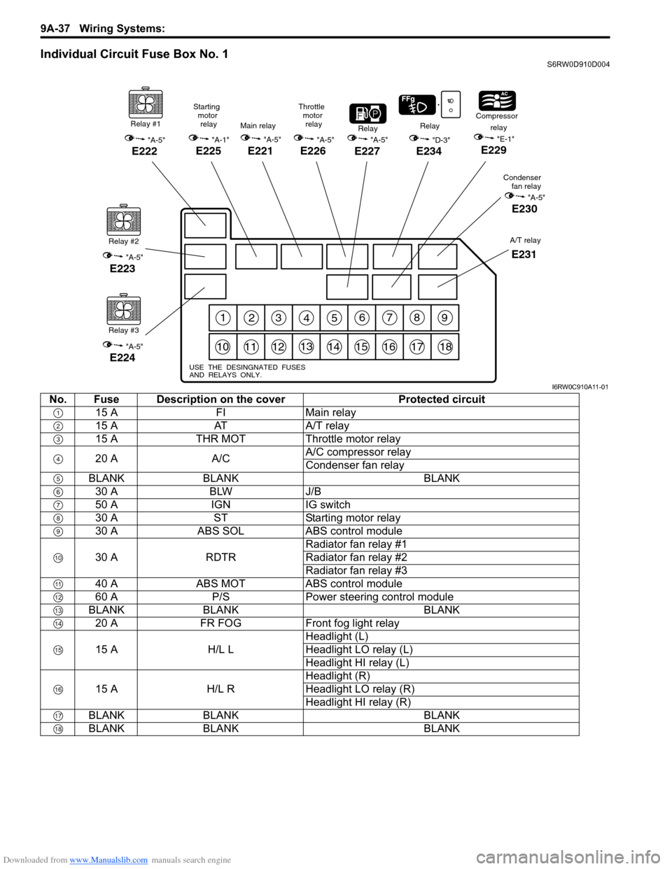
Individual Circuit Fuse Box No. 1S6RW0D910D004
123456789
101112131415161718
USE THE DESINGNATED FUSES
AND RELAYS ONLY.
Relay #1
"A-5"
E222
Relay #2
"A-5"
E223
Relay #3
"A-5"
E224
"A-5"
E227
RelayRelay
"D-3"
E234
Compressor
relay
"E-1"
E229
Condenser
fan relay
"A-5"
E230
Main relay
"A-5"
E221
Starting
motor
relay
"A-1"
E225
Throttle
motor
relay
"A-5"
E226
A/T relay
E231
I6RW0C910A11-01
No. Fuse Description on the cover Protected circuit
15 A FI Main relay
15 A AT A/T relay
15 A THR MOT Throttle motor relay
20 A A/CA/C compressor relay
Condenser fan relay
BLANK BLANK BLANK
30 A BLW J/B
50 A IGN IG switch
30 A ST Starting motor relay
30 A ABS SOL ABS control module
30 A RDTRRadiator fan relay #1
Radiator fan relay #2
Radiator fan relay #3
40 A ABS MOT ABS control module
60 A P/S Power steering control module
BLANK BLANK BLANK
20 A FR FOG Front fog light relay
15 A H/L LHeadlight (L)
Headlight LO relay (L)
Headlight HI relay (L)
15 A H/L RHeadlight (R)
Headlight LO relay (R)
Headlight HI relay (R)
BLANK BLANK BLANK
BLANK BLANK BLANK